
Related Manuals for Accuprint AP42CL 8000

Summary of Contents for Accuprint AP42CL 8000
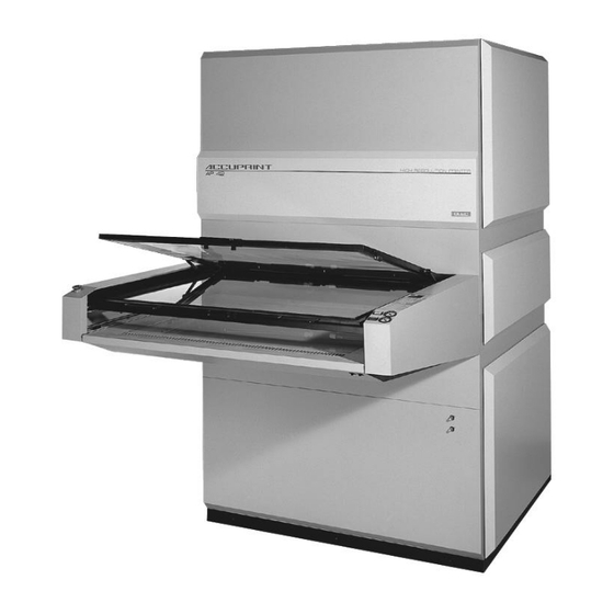
- Page 1 AP42CL 8000 Closed Loop High Resolution Printer Service Manual 94MS42 Rev. B1 S/W 2.06...
- Page 2 This manual is designed for technical personnel and should only be used by authorized Dealer service personnel. This manual is written to provide an understanding of the equipment, as well as a plan for troubleshooting. 94MS42 Rev.B1 S/W Ver 2.06...
-
Page 3: Table Of Contents
Contents Specifications Crated Dimensions ..............1-1 Shipping Weight ................1-1 Actual Dimensions ..............1-1 Effective Exposure Frame Area........... 1-2 Intensity ..................1-2 Typical Room Requirements ............1-2 Electrical specifications and connections ........1-2 Connecting power to printer ............1-4 Cooling Requirements ..............1-5 Cooling System Connecting the Evaporator ............ - Page 4 Type Mode ................... 4-8 Exposure Statistics (Elapsed Hours)..........4-9 Exposure Statistics (Total Exposures) ......... 4-9 Selecting a Memory Location............ 4-10 Quick Keypad ................4-10 Entering an Exposure Time ............4-10 Setting the Light Intensity ............4-11 Making an exposure..............4-11 Blank frame cycle ..............
- Page 5 Nose Assembly Drawings ............9-4 Nose Assembly Left and Right Covers ........9-6 10. Exposure Trays Mylar® Replacement ..............10-1 If Mylar® Pulls Out of the Frame..........10-1 Outer Frame Replacement ............10-1 Tray Assembly Drawing ............10-3 Outer Frame Assembly .............. 10-5 Inner Frame Assembly...............
- Page 6 Idle Setting................13-14 Lamp Head Blowers ..............13-15 Blown Fuse on PC Board ............13-15 Lamp Head Signals ..............13-16 Light Function States ............... 13-18 Printed Circuit Board Layout ..........13-19 Signal Description ..............13-20 Circuit Diagram (64MV407 60Hz) ........13-22 Lamphead for all Lights ............
-
Page 7: Specifications
Specifications 99" 96" Upper Tray Lower Tray 51" 48" 51" 58" 66" 61" 110" Crated Dimensions Length Width Height 130" 78" 85" 330cm 198cm 216cm Shipping Weight Crated 2,400 lbs. 1089kg Uncrated 2,000 lbs. 907kg Actual Dimensions Cabinet, welded heavy gauge steel construction, with access doors on both sides. -
Page 8: Effective Exposure Frame Area
Effective Exposure Frame Area Width 42" 107cm Depth 34" 86cm Intensity AP42CL-8000 Lamps can be operated at 8 kW, 5 kW, and 2 kW. Typical Room Requirements Circuit TOP VIEW Breaker 36" Rear 36" 36" Front Electrical specifications and connections 3 phase (Wye) See Figure A 3 wires + neutral + ground... - Page 9 380 / 415V~ 50Hz Connection 380 / 415V~ Wye: 3 Wires + Neutral + Ground OLITE Terminal Block Power Supply L1 L2 L3 Blowers Vacuum Pumps Figure A Electronics Drives Etc. Earth Ground 208/240V~ 50Hz Connection 208V~ DELTA: 3 Wires + Ground OLITE Terminal Block Power Supply #1...
-
Page 10: Connecting Power To Printer
Connecting power to printer We recommend installing a circuit breaker box within easy reach of the operator. • Install and run the main power cord through a strain relief then into the channel on the lower right rear of the printer and up to the power control box on the left side (see diagram below). -
Page 11: Cooling Requirements
Cooling Requirements Minimum pressure and flow rate of the chilled water depends on input temperature. Cl If water temperature and water flow do not meet the following specifications the unit will overheat, one or both light sources will shut themselves off randomly under heavy usage and damage to the unit could be the result. - Page 12 94MS42 Rev.B1 S/W Ver 2.06...
-
Page 13: Cooling System
Cooling System Connecting the Evaporator • Place the evaporator flat on the floor. • Connect the hose from the evaporator to the bottom of the rear panel drain. Cl Make sure the hose end on the evaporator is lower than the bottom of the rear panel drain or moisture will collect in the bottom of the Closed Loop System. -
Page 14: Connecting The Chiller
Connecting the chiller • Mount the Flow Meter and Temperature Gauge assembly on a wall in a horizontal position. Cl The Flow Meter and Temperature Gauge assembly must be mounted horizontal or the Flow Meter will not function properly. • Connect the hose from the "Water in from Chiller"... - Page 15 Connecting the chiller (cont.) ITEM Q'TY D E S C R I P T I O N : OLEC PART # NOTE SOLENOID VALVE, TWO WAY 31S0V09 SOLENOID COIL 31S0V09-C240 1/2" NPT BALL VALVE, (BLEED VALVE) 43FIT41 1"HOSE ID.BARB-1"NPT MALE PIPE 43FIT42 1"HOSE ID.BARB-3/4"NPT MALE PIPE 43FIT43...
-
Page 16: Filling The Closed Loop System
Filling the Closed Loop System Cl If the Closed Loop System is not filled properly the unit will overheat, one or both lights sources will shut themselves off randomly under heavy usage and damage to the unit will be the result. •... - Page 17 Pull the solenoid coils off the solenoid valve base, the coils are retained by a spring clip and should pull off easily, do not remove the spring clip from coils. Set the thermostat on the inside of the unit to 100°F (20°C) and turn the unit on.
-
Page 18: Closed Loop Cooling Assembly
Closed Loop Cooling Assembly 28 8 36 2 PL 2 PL 2 PL 2 PL 2 PL 4 PL 4 PL 6 4 PL REF. REF. REF. REF. Continued on next page 94MS42 Rev.B1 S/W Ver 2.06... - Page 19 Closed Loop Cooling Assembly (cont.) REF. REF. REF. DETAIL REF. DETAIL DETAIL 16 PLACES 2 PLACES 8 PLACES REF. 1/4-20 X .75 HEX HD BOLT 41-F0BHX.75 2 PL 2 PL REF. REF. REF. BRACKET, ELECTR. 11D3857A17 REF. BOX, ELECTR. COOLING MOD. 11D3984A17 FOAM, CLOSED CELL 72FOM43...
- Page 20 94MS42 Rev.B1 S/W Ver 2.06...
-
Page 21: Integrator Functions And Features
Integrator Functions and Features Microprocessor-controlled light integrator with LED display, 40 memories, battery backup, single button control, lamp statistics and self- diagnostics. The operator control panel is composed of two sections, the display board and the memory board. Note: The number of digits in each window. [ 3 9] Memory Window [ 0 120]... - Page 22 MENU This key is used as the autostep indicator and for the continuous vacuum feature. Note: U MENU Special Function The U key has the optional function to be used to set auto-step and continuous vacuum per memory in normal operating mode. The frame control switch feature must be turned ON and the automatic vacuum feature must be turned OFF.
-
Page 23: Feature Quick Reference
Feature Quick Reference The following feature descriptions appear in the exposure window while setting each feature. In order to select or setup the following features you must first be in the setup mode. [ L ocK] Lock Level Feature [ c odE] Lock Code Feature [ 2 UAL] 2 (two) Value Exposure Feature... -
Page 24: Operator Control Panel
Operator Control Panel The AP 30 heavy duty exposure system has a power key on the integrator. Press the P key to turn on the unit. • Press the P key again after use, and the system will run through a 2 •... -
Page 25: Calibration Procedures
Calibration Procedures Note: The AP42 high resolution printer has been calibrated at the factory. Note: The following calibration procedures can be applied to all three light intensities, if starting calibration from scratch. To adjust existing calibration set the integrator to 500 mj and make the exposure. -
Page 26: Changing The Calibration Number
Press the G button twice. This will send the frame into the unit and • start the exposure. After the exposure, retrieve your frame by holding down the S button • and press G button. When the frames start to move, release both buttons. -
Page 27: Matching Exposure Surfaces
Matching Exposure Surfaces • Do a test exposure in the frame being calibrated to the reference frame. • Determine the correction necessary to make each surface the same at the reference surface. If this is done with a step scale the correction is as follows. -
Page 28: Splitting Steps
Splitting Steps A densitometer can be used to assist in determining a fractional difference in step scales. When measuring density, make several measurements to avoid being influenced by pinholes. Example Original Reference Second Scale • Pick a step from the reference with a density greater than .15 and less than 2.0. -
Page 29: Integrator Program Set Up
Integrator Program Set Up To Enter the Select Mode Note: This step must be followed in several of the program set ups. Press the P key on the integrator to power up the light, the front remote • switches, and the exposure unit's computer system. [ S EL_] Press 1,2,3t 4 in sequence. -
Page 30: Lock Level Description And Operation
dim. Enter the lock level desired. Press the V key to set entry. • • If the Lock Level is set for 2, 3 or 4, the Exposure window will read [ c odE] . Enter your 3 digit code. Press the V key. -
Page 31: Setting Or Changing Your Lock Code Feature
Setting or Changing your Lock Code feature Note: If you are setting the code you must know the existing code. Note: Lock Level must be set to 0 to program this step and reset when finished see Lock Level feature. Press the P key on the integrator to power up the light, the front remote •... -
Page 32: Two Value Exposure Mode
Press the P key on the integrator to power up the light, the front remote • switches, and the exposure unit's computer system. [ S EL_] Press 1,2,3t 4 in sequence. The Vacuum window will read [ S EL_] . This places you in the select mode. Press the 9 key five (5) times. -
Page 33: Single Surface Mode
[ S Pgt] Press and release the e key until [ S Pgt] appears in the Exposure window. This places you in the split exposure option. Press the V key to cycle the split exposure mode ON or OFF. • Press the 0 key twice to exit this mode. -
Page 34: Frame Control Interface Mode
[ S EL_] Press 1,2,3t 4 in sequence. The Vacuum window will read [ S EL_] . This places you in the select mode. Press the Y key once. The Memory window will read [ S u] . • [ b cnt] Press and release the e key until [ b cnt] appears in the Exposure window. -
Page 35: Auto Step Mode
[ A UAC] Press and release the e key until [ A UAC] appears in the Exposure window. This places you in the automatic vacuum option. Press the V key to cycle the automatic vacuum mode ON or OFF. • Press the 0 key twice to exit this mode. -
Page 36: Tray Mode
Tray Mode C The default tray speed is set at the factory to 5 seconds. OLEC does not recommend changing this setting without consulting the OLEC factory. Damage to the transport can occur. Press the P key on the integrator to power up the light, the front remote •... -
Page 37: Exposure Statistics (Elapsed Hours)
Exposure Statistics (Elapsed Hours) Note: The exposure statistics should be reset to zero when the lamps are changed. Note: This provides the operating hours on the lamps in total and at each intensity since the last reset. This function should be used whenever the exposure lamps are replaced. -
Page 38: Selecting A Memory Location
[ E HI_] Press the 2 key. The letters [ E Hi_] will appear in the Vacuum window. The Exposure window will display the number of exposures made at high power. [ E Lo_] Press the 2 key a second time. The letters [ E Lo_] will appear in the Vacuum window. -
Page 39: Setting The Light Intensity
Setting the Light Intensity Press the I key to set intensity. Press I for the first time. The first • LED on the left indicates the intensity is set to low 2kW. Press: I for the second time. The first two LEDs light to indicate the Medium •... -
Page 40: Error Handling System
Error Handling System If an error occurs, the machine displays an error code to aid in troubleshooting. The error codes defined are: [ E rr_] The message [ E rr_] will appear in the Vacuum window, and a number in the Exposure window. Look up the number below for a description of the condition. -
Page 41: Diagnostics
Diagnostics Output Diagnostics One of the many advancements OLEC has introduced to the field is the ability of its equipment to run a self-diagnostic check. All computer- activated functions and all internal and external switches can be checked out on the integrator display by using the numerical keypad. Output Functions Check Press the P key on the integrator to power up the light, the front remote •... -
Page 42: Functions Table
Functions Table Function Value [ 0 001] Heat Exchanger Solenoids [ 0 002] Blower On/Off [ 0 004] Upper Vacuum Pump O n/Off [ 0 008] Lower Vacuum Pump On/Off [ 0 016] Work Light and Nose Section Fans O n/Off [ 0 032] Motor Direction Control [ 0 064]... -
Page 43: Input Diagnostics
Input Diagnostics • Switch Check The switch check can be done while in the Select mode. Press the P key on the integrator to power up the light, the front remote • switches, and the exposure unit's computer system. [ S EL_] Press 1,2,3, then 4 in sequence. -
Page 44: Typical Values That You Will See When A Fault Occurs
• Lower tray in, Frame switch closed, Door and Emergency switches closed. [ 0 044] The Exposure window should read [ 0 044] . [ 0 172] When the G button is pushed the value should change to [ 0 172] . [ 0 060] When the S button is pushed the value should change to [ 0 060] . -
Page 45: Lamp Changing Instructions
Lamp Changing Instructions W The lamps and safety glass may be very hot and cause burns. Prior to changing the lamp, ensure the lamp head is turned off and allowed to complete its cooldown cycle. OLEC recomends that every year you unplug your light, remove the safety glass, and clean the glass and reflector with denatured alcohol and a soft cloth. - Page 46 reflectors and glass can substantially reduce light output. • Wear the white lightweight fabric gloves that are provided and unpack the new lamp. Clean the lamp with the alcohol wipe included. • Place each end of the new OLITE lamp (one end at a time) on the holders. DO NOT touch the lamp with your hands.
-
Page 47: Preventive Maintenance
Preventive Maintenance Preventive Maintenance Daily (Approximately 15 minutes required) • Clean exposure frame glass and Mylar. The exposure frame glass and Mylar should be kept meticulously clean. Dirt and resist flakes on these surfaces will cause exposure defects. • Inspect Mylar for cuts and tears. Check the condition of the Mylar on both exposure frames. - Page 48 C Do not use silicone spray lubricants in the printer. • Lubricate frame drive chain and check tension. • Apply a light coat of machine oil to the exposure frame drive chain by rubbing an oil wetted rag along the chain. Do not wet the chain enough to cause the oil to run or drip.
-
Page 49: Vacuum System
Vacuum System Vacuum Pumps Description: The printer uses two -hp oilless rotary vane vacuum pumps, one for each exposure frame. Pressing the G button on the front nose assembly activates the pump for frame that is out of the cabinet. The vacuum gauge on the front panel indicates which pump is activated. -
Page 50: Pump Disassembly
Flushing Option #1 This option requires two pipe nipples at least 4" (102 mm) long with " NPT threads on one end. • Remove the filter elements from the front of the muffler box and screw the nipples into the same holes. •... -
Page 51: Pump Replacement
voltage at the pump. If voltage is present at the pump connector, but the pump fails to operate, replace the pump. If the control box LED is not on, check the wiring and connections from the switch to the control box. Pump Replacement Vacuum pump replacement is straightforward. -
Page 52: Tubing/Fitting Replacement
Tubing/Fitting Replacement If a vacuum line or connection is cracked, loose, leaking or broken, replace it as soon as possible. A faulty vacuum line or connection will greatly increase the vacuum drawdown time required, if not eliminate full vacuum altogether. All vacuum lines are separated from the connectors by pressing down and holding the connection outer ring while pulling the vacuum line out. -
Page 53: Vacuum Seal Replacement
Vacuum Seal Replacement A cut, torn or otherwise damaged vacuum frame seal will greatly inhibit, if not prevent, full vacuum. A bad seal can be lifted and peeled off the frame glass. If necessary, use a razor blade or other suitable item to remove any leftover seal adhesive. - Page 54 Vacuum Seal Replacement (cont.) • Unless otherwise specified Dimensions are in inches. Dwg. per ANSIY14.5 Tolerances are: Angles ±5 deg. .X±1 .XX±.03 .XXX±.010 .XXXX±.0030. • Clean glass perimeter. Press transfer tape onto glass. (as shown) Trim tape along edge of glass. Peel off paper. •...
-
Page 55: Phototool Wiring Diagram (Optional)
Phototool Wiring Diagram (optional) If the unit is equipped with the Glass Photo Tool Option you will have a third vacuum pump installed in the bottom of the unit. See Vacuum Pumps and Tubing/Fitting Replacement for vacuum problems. Several different glass tools are available according to customer needs so each tool itself is going to be different, however the electrical wiring and operation is the same. - Page 56 94MS42 Rev. B1 S/W Ver 2.06...
-
Page 57: Nose Assembly
Nose Assembly Removing the Left and Right Rail Covers • Turn unit OFF, allow the unit to complete its cool down cycle and disconnect power. • To remove rail covers: • To remove the right rail cover: While standing in front of the unit locate and disconnect all multi-pin connectors and vacuum lines below the rail cover on the right side. -
Page 58: Replacing The Glass Tool Vacuum Buttons
• Use a small screw driver inserted between the switch and the sheet metal to break the glue holding the two black retainer clips on each side of the switch from the rail cover. • Press together the switch retainer clips on the base of the switch and push the switch out through the top. -
Page 59: Work Lights
Work Lights Note: The work lights are controlled by a rocker switch on the underside of the right front corner of the nose cover. Note: If the work lights are not turning ON, check the rocker switch and power to the switch. Note: The work lights receive their power from the autoformer in the nose section •... -
Page 60: Nose Assembly Drawings
Nose Assembly Drawings 4 PL 4 PL 2 PL BOTTOM VIEW -------------------- -------------------- HARNESS, SW, OPERATOR OV45 16D2196A00 -------------------- -------------------- -------------------- -------------------- SWITCH, CW 55SW01 -------------------- -------------------- -------------------- -------------------- -------------------- -------------------- NSI 8-32 X 3/8 PPMS ZINC 41-08PPS.37 -------------------- -------------------- -------------------- -------------------- --------------------... - Page 61 Nose Assembly Drawings (cont.) 3 PL 3 PL 4 PL 14 PL 6 PL 5 PL 2 PL 2 PL 4 PL 3 PL 4 PL 2 PL REF. 4 PL TOP VIEW 5 PL 4 PL 46 43 36 Continued on next page 94MS42 Rev.B1 S/W Ver 2.06...
-
Page 62: Nose Assembly Left And Right Covers
Nose Assembly Left and Right Covers 10 PL 10X 2 PL FRAME DETAIL A 4X 2 PL 10 PL Mounting bolts DETAIL B BARRIER 55SW45-5 SUPPORT, RAIL COVER-OV45 11D2535A08 ADHESIVE, SQUARE 4026 44PAD02 NSI 6-32 KEP NUT ZINC 41 06NKP 2 PL NSI #6 INTERLOCK LOCK WASHER 41 06WLI... -
Page 63: 10. Exposure Trays
10. Exposure Trays Mylar® Replacement • Close the Mylar® frame and open the twelve cam latches. • Remove the inner Mylar® frame and position a pre-cut Mylar® sheet into the frame. Make sure that the Mylar® is overlapping on all sides. Closed Position Open... - Page 64 • Place the new frame flat on the tray. Line up and insert the Allen head screws through the hinge into the frame. Make sure the frame is " to " above the top of the hinge to avoid the possibility of damaging the glass, then tighten them down.
-
Page 65: Tray Assembly Drawing
Tray Assembly Drawing 2 x 37" 2 x 43.25" 4 PL 2 PL 2 PL 2 PL DETAIL A 2 PL 2 PL 2 PL 2 PL 2 PL 4 PL 2 PL 2 PL DETAIL C 10 PL DETAIL B 2 PL 2 PL 2 PL... - Page 66 Tray Assembly Drawing (cont.) GAS SPRING (80 LBS) 43SPR24 161" ADHESIVE RUBBER GASKET SEE BOM HINGE BLOCK CLAMP 19D3815A02 NSI CABLE TIE, UV, 4" 44TIE08 16D2970A99 CABLE, MAGNETIC TRAY SWITCH NSI 6-32 X 1/2 PHIL PAN BLK 41BO6PPS.50 NSI #6 KEP NUT ZINC 41-06NKP RAMP SWITCHES, AP30/OV33 11D2112A62...
-
Page 67: Outer Frame Assembly
Outer Frame Assembly 2 PL 2 PL 32 38 PL (GLASS TRAY ASSEMBLY) REF. REF. 2 PL 2 PL 2 PL 2 PL REF. 6 PL 2 PL ADD WASHERS IF NEEDED TO ADJUST CATCH TO LATCH 2 PL 2 PL LATCH / HANDLE ASSEMBLY SIDE VIEW VIEW... -
Page 68: Inner Frame Assembly
Inner Frame Assembly CUT TO LENGTH AND APPLY AS SHOWN REFERENCE VIEW B 6 PL 16 12 PL 12 PL 18 33 12 PL 12 PL 10 25 12 PL 4 PL REF. VIEW B 2 PL 2 PL INNER FRAME ASSEMBLY BOTTOM VIEW 2 PL 28 22... -
Page 69: Gas Spring Removal And Replacement
Gas Spring Removal and Replacement Each frame assembly has two gas springs to support the top cover sheet frame when it is opened. • Open the frame with the spring to be replaced. Cl The glass frame assembly is heavy, make sure you support it well before removing the gas spring. -
Page 70: Frame Glass Replacement
• Unplug the drive motor electrical connector from the control box and position both frames near the mid-travel position. • Remove three linear bearing retainer block screws using a " Allen wrench. • Lift up the frame assembly about 2" (51 mm) and slide the bearing block assembly backward off the shaft, support the frame to prevent contact with the shaft. -
Page 71: 11. Center/Drive Assembly
11. Center/Drive Assembly Center/Drive Assembly Diagram 4 PL 4 PL DRIVE MOTOR ASSY. DETAIL A 5 PL 4 PL 14 PL TIMING SWITCH ASSY. DETAIL C. 21 PL 2 PL 3 PL CHAIN TENSIONER ASSY., DETAIL B. 6 PL 3 PL 2 PL 93.5"... - Page 72 Center/Drive Assembly Diagram (cont.) NSI #8 FLAT WASHER 41BO8WFR 5/16 SPLIT LOCK WASHER 41F2WLS SOCKET HEAD FLAT #5/16-18 X .62 41BF2SHF.62 INSULATION PAD AL13/14 15D725 COVER, DRIVE CHAIN-LOWERLD. 11D2799B08 COVER, DRIVE CHAIN-UPPER 11D2799A08 NSI 6-32 X 3/8 PHIL FLAT 41 06PFO.37 NSI 3/8 X A3/4 SOC.
-
Page 73: Tray Transport System
Tray Transport System The printer has two aluminum exposure tray assemblies. Vacuum for frame evacuation is drawn through two ports in the glass, one at each of the rear corners. The top Mylar® frame is hinged in the back, with a gas strut on each side that holds the Mylar®... -
Page 74: Tray Speed Adjustment
will be too slow and a transport error may occur. Use the following procedure to set the clutch at the minimum setting for operation. • Remove the left side center panel on the printer and locate the clutch at the left rear corner. •... - Page 75 Press the 6 key again: upper tray should move in, the vacuum window • should read [ 0 096] . • Set Volt meter for VDC and measure across pins 5 & 6 on motor speed connector. Adjust the 'SLOW' pot on the control box to read 25 to 32 VDC.
-
Page 76: Light Block Assembly
Light Block Assembly Upper Light Block (center section) Assembly Drawing REF. 14 PL 2 PL 2 PL 2 PL 2 PL 2 PL 2 PL BOTH SIDES 2" 4 PL REF. REF. 5 PL 5 PL TORS. SPRING ASSY., RH SIDE. DETAIL E 62D2321A00 WHEEL ASS'Y. -
Page 77: Lower Light Block (Insert Section) Assembly Drawing
11D2051A62 #1/2 FLAT WASHER 41-F5WFR NSI 1/2-13 X 2.0SHCS-BLK 41BF5SHC2.0 NSI 6-32 X .312 HEX THD SPACER 42HHS9292 ACCUPRINT PCB, MASTER 64MI441E-APM ACCUPRINT PCB, REMOTE 64MI441E-APR NSI 36 INTERNAL LOCK WASHER 41-06WLI NSI 6-32 X 3/16 PPMS ZINC 41 06PPS.18... -
Page 78: Replacing Light Block Springs
Replacing Light Block Springs • For the lower light block, move upper exposure frame into the cabinet. For the upper light block, move lower exposure frame into the cabinet. • Disconnect main power. • Remove the left and right side panels. •... -
Page 79: 12. Diagrams
12. Diagrams Control Box Front View Typical SET SELECT SWITCH TO SLOW FAST LINE UP WITH SPEED MOTOR COMMUNICATION LED INDICATOR LIGHT 12 VDC SLOW STOP Blk Red Blk Red LINE VOLTAGE Wht Red Blk Wht Org Wht Blk Blk Red Blk Red SELECTION MOTOR VACUUM... -
Page 80: Control Box Wiring Diagram
Control Box Wiring Diagram 208VAC 60Hz/380VAC 50Hz 12-2 94MS42 Rev.B1 S/W Ver 2.06... - Page 81 480VAC 60Hz 94MS42 Rev.B1 S/W Ver 2.06 12-3...
-
Page 82: Base Assembly Diagram
Base Assembly Diagram 4 PL 24 PL 12 PL 24 PL 12 PL 3 PL .25 - .31 TYP. Continued on next page 12-4 94MS42 Rev.B1 S/W Ver 2.06... - Page 83 Base Assembly Diagram (cont.) DETAIL 26 PL DETAIL 12 PL REF. REF. DETAIL 2 PL DETAIL 7 PL DETAIL 4 PL REF. DETAIL 4 PL WELDMENT, COOLING COMPARTMENT 11D3751A00 DOOR PANEL, CENTER 11D3717A00 SCREW, #10-32 X 1/2 SOC.BUTN. HD 41B12SHB.50 DETAIL SCREW, #10-32 X 3/8 PH.PAN HD.
- Page 84 12-6 94MS42 Rev.B1 S/W Ver 2.06...
-
Page 85: Unit Cabling Diagram (New Style)
Unit Cabling Diagram (new style) BLOWER (120V) BLOWER (NOSE) 240V 16D3793A00 16D3794A00 (120V) BLR5 BLR6 (RED, 22 GA) (RED, 22 GA) (NOSE) (BLACK, 22 GA) (BLACK, 22 GA) (BROWN, 18 GA) 16D2621B00 120V (GRAY, 5 COND.) (BROWN, 18 GA) 16D1003A15 (BLACK, 5 COND.) (BLUE, 18 GA) 16D1003A06... -
Page 86: Unit Cabling Diagram (Old Style)
Unit Cabling Diagram (old style) 16D3794A00 (RED, 22 GA) BLOWER (120V) (BLACK, 22 GA) BLOWER (NOSE) 16D3793A00 240V (120V) (RED, 18 GA) (RED, 22 GA) (NOSE) (BLACK, 18 GA) (BLACK, 22 GA) 16D2621B00 (GRAY, 5 COND.) 16D1003A15 (BLACK, 5 COND.) (BROWN, 18 GA) 120V (BROWN, 18 GA) -
Page 87: 13. Light Source
13. Light Source Component Layout Lamphead for AL 84 and AL 94 50/60Hz 55SW02 64MV414 62SA83 L1280, L1281 or L1282 63D0142 39BLO14 Shutter Position Switch Trigger Board Shutter Assembly Replacement Lamp Lamp Support Assembly Blower Interconnect Cable To Power Supply 90RF83-C Reflector 31MOT06 39BLO14... - Page 88 Power Supply for AL 84-480 60Hz Power Supply for AL 94 50Hz 13-2 94MS42 Rev. B1 S/W Ver 2.06...
-
Page 89: Ballast/Tap Switch Wiring
Ballast/Tap Switch Wiring AL 94 Ballast Wiring TERMINAL STRIP NO. 29 (VIOLET). AC IN 6 GA. CONTACTOR NO. 20 (ORANGE TO CAP. PACK). BALLAST BALLAST BALLAST BALLAST AL 84 Ballast / Tap Switch Wiring TERMINAL STRIP AC IN 6 GA. CONTACTOR ORANGE TO CAP. -
Page 90: Path Of Power To The Pc Board
AL 84-480 Ballast Wiring TERMINAL STRIP NO. 29 (VIOLET). AC IN 6 GA. CONTACTOR NO. 20 (ORANGE TO CAP. PACK). BALLAST BALLAST BALLAST BALLAST Path of Power to the PC Board • This section is useful when there is no power reaching the PC board (no LEDs lighted). -
Page 91: Lamp Voltage
• The internal interlock is a loop that travels through the light head, passing through the glass switch and two thermostats. This interlock is in series with the control circuit of the large relays in the power supply. When the interlock is opened, the relays will open and cut the power to the lamp terminals. -
Page 92: Trigger Board
Trigger Board A trigger board is provided in the light head to start the lamp. This board operates on demand by sensing the lamp voltage. This board can be heard when it is functioning, although the sound is faint. By turning the unit on and off, the sound can be compared during trigger and cool-down. - Page 93 capacitor we use will burn open if it begins to short. A swollen capacitor should be replaced, and the unit should be tested to see that the capacitor did not damage the high or medium relay. To test the unit’s ability to switch power levels, make a manual exposure, then switch between the power levels, noting the change in intensity.
- Page 94 AL 94 Capacitor Assembly WIRES FROM HARNESS CAPACITOR ASSEMBLY PART # 62D2723A00 1 2 3 FRONT VIEW OF 12µƒ 16µƒ PC BOARD WIRES TO CAPACITOR SWITCH ON CAPACITOR MOUNTING BRACKET 4µƒ 12µƒ 16µƒ 4 3 2 1 WIRE COLORS 1) YELLOW REAR VIEW OF 2) BROWN PC BOARD...
-
Page 95: Opening The Lamp Head
Opening the Lamp Head • Unplug the unit. • Remove the glass and the four screws attaching the large outer reflector section. C DO NOT TOUCH THE REFLECTOR SURFACE WITH YOUR HANDS. Bottom View Remove the 2 center screws from the bottom side and the 2 screws from the top side of the lighthead. -
Page 96: Shutter Switch
Shutter Switch The switch provides shutter position information to the PC board. This switch is in the lamp end where the cable enters, inside the manifold cover. The cam is in the chamber with the shutter. A failure of the switch can cause the shutter to rotate continuously or erratically. -
Page 97: Installing The Motor
C Turn the shutter only counterclockwise (looking from the motor end) or you may damage the shutter switch on the other end of the light. • Remove the chain from the sprocket with care to keep tension. The chain has shortened links and will separate if slackened. If the chain opens, attach an end to the sprocket with tape or wire and revolve the shutter. -
Page 98: Shutter Removal
Shutter Removal LT8 lampheads • Remove the four hex nuts mounting the blowers, disconnect the blower and thermostat wires. View • Remove the four screws holding the rear reflector to the cooling tubes and remove the reflector and lamp from the lamp head. C DO NOT TOUCH THE REFLECTOR SURFACE WITH YOUR HANDS. -
Page 99: Lt8 Shutter Assembly Drawing
LT8 Shutter Assembly Drawing 4 PL 4 PL 4 PL REF. REF. REF. DETAIL DETAIL REF. DETAIL 4 PL 4 PL REF. REF. 2 PL 17 25 SECTION 8 PL SECTION DETAIL REF. DETAIL E REF. DETAIL D DETAIL REF. DETAIL A 2 PL DETAIL... -
Page 100: Idle Setting
Idle Setting • The idle level occurs between exposures and low power exposures. The idle setting determines the power and temperature of the lamp, while at idle. It also allows for much lower idle power than was ever attainable before. •... -
Page 101: Lamp Head Blowers
Lamp Head Blowers • The lamp head blowers are controlled by the printed circuit board to provide the correct cooling to the lamp. During warm-up, the blowers are off or run very slowly. At idle and during low exposure, the blowers vary in speed. -
Page 102: Lamp Head Signals
Lamp Head Signals Signals at the Terminal Strip (Cable to the Lamp Head) A great deal of information about the operation of the lamp may be found at the terminal strip, in the power supply that connects to the lamp head. The terminals are counted number 1 at the end where the cable begins, and wire number 18 is the last wire. - Page 103 rises it increases. As the lamp reaches temperature, the fans speed increases to regulate the lamp. At idle, this voltage is typically 45 - 90V~ and depends on the lamp age and ambient temperature. When an exposure at high power is initiated, the lamp voltage rises to the maximum. The voltage remains there after the lamp returns to low power, until the lamp temperature again stabilizes.
-
Page 104: Light Function States
Light Function States Model Warm-Up Idle Low Exp. Med Exp. High Exp. Cool Down Trigger Unit Fans On / On On / On On / On On / On On / On On / On On / On Power Relay On / On On / On On / On... -
Page 105: Printed Circuit Board Layout
Printed Circuit Board Layout This is a description of the signals and voltages present on the pins of the printed circuit board. 64MV407V24 Control Board layout. Note: Graphic of the new style p.c.board is shown. Relay style p.c.board has the same connector hookups and pin outs, however the LEDs are on the component side of the p.c.board not on the solder side as on the new style. -
Page 106: Signal Description
Signal Description Power Connector V~ Hot: Supply to board approximately 125V~. V~ Common: Common to board is the common also for relays, shutter fans, and the internal lamp head interlock. (This may not be at ground potential and should be measured with caution). Lamp Fans: V~ proportional drive output for the blowers in the lamp head. - Page 107 Switch Connection (cont.) High Switch: Switch to select high power level. Low (0V) for high. Low/Med Switch: Switch to select power level when high switch is off. Low (0V) for medium power, High (12VDC) for low power. Manual Switch: Manual expose switch. Low (0V) to cause exposure. Interlock: External interlock outlet.
-
Page 108: Circuit Diagram (64Mv407 60Hz)
Circuit Diagram (64MV407 60Hz) 13-22 94MS42 Rev. B1 S/W Ver 2.06... -
Page 109: Lamphead For All Lights
Lamphead for all Lights Thermostat Thermostat Shutter Position Switch Safety Glass Switch Shutter Motor Blowers Lamp Trigger Board 94MS42 Rev. B1 S/W Ver 2.06 13-23... -
Page 110: Al 84 Power Supply 60Hz
AL 84 Power Supply 60Hz 220 VAC 50HZ INPUT Tap Switch Voltage Toward Selection front of unit Board Safety Interlock Power Relay Ballast Ballast 3 Amp Slow Blow Socket 10µƒ 16µƒ 12µƒ 12µƒ Fuse 10 blu Medium High Relay Relay 5 wht Power Supply... -
Page 111: Al 84-480 Power Supply 60Hz
AL 84-480 Power Supply 60Hz 120 VAC 60HZ INPUT 480 VAC 60HZ INPUT Toward front of unit Safety Interlock Power Relay Ballast Ballast Socket 10µƒ 10µƒ 12µƒ 12µƒ 10 blu Medium High Relay Relay 5 wht Power Supply Blower 12 gry 11 org 10 brn 8 red/wht... -
Page 112: Al 94 Power Supply 50Hz
AL 94 Power Supply 50Hz 220 VAC 50HZ INPUT Toward front of unit Safety Interlock Power Relay Ballast Ballast 3 Amp Slow Blow Socket 16µƒ 12µƒ 4µƒ 16µƒ 12µƒ Fuse Position 2 Position 1 10 blu Medium High Relay Relay Power Supply Blower... -
Page 113: Interconnect Cable
Interconnect Cable WHITE GREEN YELLOW VIOLET BLUE BROWN ORANGE HEAT SHRINK BLACK WHITE GREEN YELLOW VIOLET BLUE BROWN ORANGE HEAT SHRINK BLACK 94MS42 Rev. B1 S/W Ver 2.06 13-27... - Page 114 13-28 94MS42 Rev. B1 S/W Ver 2.06...
-
Page 115: 14. Printing Light Check List
14. Printing Light Check List Check List for Printing Light Troubleshooting and Service C In order for this check list to be effective it must be followed step by step. 1) Disconnect the integrator/timer from the power supply. This will make sure that a faulty integrator or cable is not responsible for the malfunction and also eliminate a bad DIN socket on the p.c.board. - Page 116 • You must be able to reach up, place your fingers against the safety glass and there must be play front to back and side to side. Otherwise the glass does not have room for expansion and will more than likely shatter under use.
- Page 117 8) Check capacitors and relay circuit by: The capacitors and relays are checked by watching the voltage changes that take place at the different intensity levels. If a capacitor is not in the circuit the voltage readings on input and output will be the same. If the capacitor is pulled into the circuit the input and output voltages will be hundreds of volts apart.
- Page 118 8kW with L1280 LAMP ORANGE YELLOW BROWN BLUE #1 BLUE #2 IDLE 700+ 700+ 700+ 700+ 700+ 700+ 700+ 700+ MEDIUM 700+ 700+ 700+ HIGH 700+ 8kW with L1281 LAMP ORANGE YELLOW BROWN BLUE #1 BLUE #2 IDLE 700+ 700+ 700+ 700+ 700+...
- Page 119 checks affect the operation and can make them appear to be operating incorrectly. Also check blower voltage at terminals 4 & 5 for most lights this voltage should be a MINIMUM of 65V~ to 75V~ some lights this voltage will be higher depending on lamp used and lamp condition. 14) Check for cooling obstructions on intakes and exhausts.
- Page 120 26) Before you reassemble everything it is a real good idea to: Check the manual operations of the light source. Just to make sure everything is back together. 27) Reconnect all wires to the integrator and then: Check the remote operations of the light source from the integrator.
-
Page 121: 15. Fault Trees
15. Fault Trees No Strike Fault Tree Does shutter rotate when light turned on? Are any LED's Check Safety Glass Good and Lever lit on the PC Board? Good Reinstall safety glass Test 1 Go to test 2 after Is power relay pulling in? Go to test 1 checking PC Board fuse... -
Page 122: Shutter Rotation Fault Tree
Shutter Rotation Fault Tree Is the lamp lit? Does shutter rotate at any time? Is LED #D17 lit The shutter will on PC Board not open for an exposure w/o the lamp being Does shutter seem lit. Go to the When LED #D17 is lit, check for to bind during No Strike Fault... -
Page 123: Drive Motor Fault Tree
Drive Motor Fault Tree Manually position both frames in a mid position Turn unit on Does upper frame move into unit? Wait 20 seconds. Does lower frame move Does integrator into unit display an error message? Motor speed controller Check for DC output Refer to Err Try a blank tray wires, A1, A2, reversed... - Page 124 15-4 94MS42 Rev.B1 S/W Ver 2.06...
-
Page 125: 16. Parts List
16. Parts List Part Number Description Qty. per unit 62AP42CL Base Kit AccuPrint Closed Loop 39VAP05 Vacuum Pump 230 V 60 HZ 55SW45-6 Button, white ‘GO’ 55SW45-7 Button, white ‘STOP’ 62D3542A00 Assembly Rail Cover, OV45 62D3705A00 Base Assembly AP 42CL... - Page 126 Part Number Description Qty. per unit 43SPR17 Spring, Tors. LH 43SPR18 Spring, Tors, RH 44GKT01 Gasket, 1/16 Thick 44TIE08 NSI Cable Tie, UV 55SW02 Switch, Timing 55SW55 Pushbutton switch 62D2321A00 Assembly, Wheel, Lig 62D3706A00 Exposure tray(Lower) 62D3706B00 Exposure tray(Upper) 62D3707A00 Seal, Glass AP42CL 62D3798A00 Ass’y drive mtr w/co...
- Page 127 Part Number Description Qty. per unit 43FIT46 Reducer nipple-male 43FIT49 Female Conn. 1"NPT Brass 43FIT51 Male-female elbow 43FIT52 Female tee, Brass, 1"NPT 43FIT54 Cross-female, "NPT 43FIT57 Hex nipple-male 43FIT58 Bushing,femal-male 1" x " 43FIT60 Female elbow, "NPT 43FIT65 "NPT male branch ‘T’ 43FIT66 Nipple, 6"...
- Page 128 Part Number Description Qty. per unit 49VAV01 Valve, Vacuum Relief 62D2321A00 Assembly, Wheel, Light Bl 62AP42CL-NSA Assy Nose Fan/Work Light 11D1939A62 Bracket, Filter Holder 11D1939B62 Bracket, Filter Holder 11D3733A07 Reflector, Worklight 11D3734A08 Air Director No 1 11D3735A08 Air Director No.2 11D3736A08 Air Director No.3 11D3746A17...
- Page 129 Fuse, 1/2A 250V 3AG Slow 56FUS28 Fuse, 10A 250V, Slow Blow 62D2483A00 Blower, 220V 62D331A Voltage Selector Assembly 64CT464 PCB Assembly. AccuPrint 62D3558A Assy,Ctrl Bx-8K CLS,GT, 480 60hZ 15D3586A00 Label, Wiring Conn 480V 16D3074A00 Harness, Control Box Supl 16D3208A00 Harness, Cntrl Bx -GTools...
- Page 130 Fuse, 1/2A 250V 3AG Slow 56FUS28 Fuse, 10A 250V, Slow Blow 62D2483A00 Blower, 220V 62D331A Voltage Selector Assembly 64CT464 PCB Assembly. AccuPrint 62AL85-L2 Printing Light with L 1282 208/240 60Hz 2 62CL85-8K CL85 Power Supply 208/240 60Hz 16D1045A00 Harness, Beau Plug OEM 16D1585...
- Page 131 Part Number Description Qty. per unit 62CL84-480-L2 Power Supply 480V 60Hz,8K 16D2617B00 Power Cable, AL85-AP42 PS 16D1045A00 Harness, Beau Plug 16D1585 Interlock Harness 16D2617A00 Power cable 16D2629A00 Harness, 8K-B P/S - main 32BAL01 Ballast, AL 83 33RLY02 Contactor, 2 pole,NO,30Amp 33RLY04 Relay, Sealed 39BLO03...
- Page 132 Part Number Description Qty. per unit 55SW03 Switch, Glass, 2 Pos Blk 56THM01 Thermostat, model K 62LHK01 Switch Assembly 63D3669A00 Idler, Arms Assy LT8 64MV414-T Trigger Board Tested 8K 16-8 94MS42 Rev.B1 S/W Ver 2.06...
-
Page 133: 17. Warranty
17. Warranty OLEC Limited Warranty OLEC equipment is warranted against defects in material for ONE (1) Year from date of purchase. Faulty parts will be repaired, replaced, or purchase price refunded at OLEC's option, for the original Buyer, provided the parts have been replaced by authorized personnel and are returned prepaid to the OLEC factory in Irvine, CA. - Page 134 Corporation 17112 Armstrong Avenue, Irvine Ca U.S.A. 92614 U.S.A. (949) 399-6500 Fax (949) 399-6501...
Need help?
Do you have a question about the AP42CL 8000 and is the answer not in the manual?
Questions and answers