Sign In
Upload
Manuals
Brands
Accuprint Manuals
Printer
AP42CL 8000
Accuprint AP42CL 8000 Manuals
Manuals and User Guides for Accuprint AP42CL 8000. We have
1
Accuprint AP42CL 8000 manual available for free PDF download: Service Manual
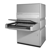
Accuprint AP42CL 8000 Service Manual (134 pages)
Closed Loop High Resolution Printer
Brand:
Accuprint
| Category:
Printer
| Size: 1.68 MB
Table of Contents
Table of Contents
3
1 Specifications
7
Crated Dimensions
7
Shipping Weight
7
Actual Dimensions
7
Effective Exposure Frame Area
8
Intensity
8
Typical Room Requirements
8
Electrical Specifications and Connections
8
Connecting Power to Printer
10
Cooling Requirements
11
2 Cooling System
13
Connecting the Evaporator
13
Connecting the Chiller
14
Filling the Closed Loop System
16
Checking the Chiller
16
Closed Loop Cooling Assembly
18
3 Integrator Functions and Features
21
Integrator
21
Feature Quick Reference
23
Operator Control Panel
24
Calibration Procedures
25
Changing the Calibration Number
26
Matching Exposure Surfaces
27
Splitting Steps
28
Matching with a Meter
28
4 Integrator Program Set up
29
To Enter the Select Mode
29
Lock Level Feature
29
Lock Level Description and Operation
30
Setting or Changing Your Lock Code Feature
31
To Clear Lamp Statistics
31
To Clear Memory and Exposure Statistics
31
Two Value Exposure Mode
32
Split Exposure Mode
32
Single Surface Mode
33
Board Count Display Mode
33
Frame Control Interface Mode
34
Automatic Vacuum Mode
34
Auto Step Mode
35
Set Default Vacuum Delay
35
Tray Mode
36
Type Mode
36
Exposure Statistics (Elapsed Hours)
37
Exposure Statistics (Total Exposures)
37
Selecting a Memory Location
38
Quick Keypad
38
Entering an Exposure Time
38
Setting the Light Intensity
39
Making an Exposure
39
Blank Frame Cycle
39
Error Handling System
40
5 Diagnostics
41
Output Diagnostics
41
Output Functions Check
41
Functions Table
42
Input Diagnostics
43
Typical Values that You will See When All Switches Are Good
43
Typical Values that You will See When a Fault Occurs
44
6 Lamp Changing Instructions
45
Lamp Changing Instructions
45
7 Preventive Maintenance
47
Preventive Maintenance Daily
47
Preventive Maintenance Monthly
47
Preventive Maintenance Semi-Annually
47
8 Vacuum System
49
Vacuum Pumps
49
Flushing the Pump
49
Pump Disassembly
50
Pump Check
50
Pump Replacement
51
Tubing/Fitting Replacement
52
Vacuum Gauge Replacement
52
Vacuum Seal Replacement
53
Phototool Wiring Diagram (Optional)
55
9 Nose Assembly
57
Removing the Left and Right Rail Covers
57
Replacing the Display and Keypad PC Board
57
Replacing the Z Emergency Stop Button
57
Replacing the S and G Buttons
57
Replacing the Glass Tool Vacuum Buttons
58
Replacing the Vacuum Gauges
58
Nose Section Autoformer
58
Work Lights
59
Nose Fans
59
Cleaning or Replacing Nose Filters
59
Nose Assembly Drawings
60
Nose Assembly Left and Right Covers
62
10 Exposure Trays
63
Mylar® Replacement
63
If Mylar® Pulls out of the Frame
63
Outer Frame Replacement
63
Tray Assembly Drawing
65
Outer Frame Assembly
67
Inner Frame Assembly
68
Gas Spring Removal and Replacement
69
Replacing the Linear Bearings
69
Frame Glass Replacement
70
11 Center/Drive Assembly
71
Center/Drive Assembly Diagram
71
Tray Transport System
73
Tray Drive Motor Replacement
73
Tray Drive Clutch Adjustment
73
Tray Speed Adjustment
74
Light Block Assembly
76
Lower Light Block (Insert Section) Assembly Drawing
77
Replacing Light Block Springs
78
12 Diagrams
79
Control Box Front View Typical
79
Control Box Wiring Diagram
80
Base Assembly Diagram
82
Unit Cabling Diagram (New Style)
85
Unit Cabling Diagram (Old Style)
86
13 Light Source
87
Component Layout
87
Ballast/Tap Switch Wiring
89
Path of Power to the PC Board
90
Interlock System
90
Lamp Voltage
91
Lamp Power Path
91
Trigger Board
92
Capacitors and Level Switching
92
Opening the Lamp Head
95
Shutter
95
Shutter Switch
96
Shutter Brake
96
Shutter Motor
96
Installing the Motor
97
Shutter Removal
98
LT8 Shutter Assembly Drawing
99
Idle Setting
100
Lamp Head Blowers
101
Blown Fuse on PC Board
101
Lamp Head Signals
102
Light Function States
104
Printed Circuit Board Layout
105
Signal Description
106
Power Connector
106
Circuit Diagram (64MV407 60Hz)
108
Lamphead for All Lights
109
AL 84 Power Supply 60Hz
110
AL 84-480 Power Supply 60Hz
111
AL 94 Power Supply 50Hz
112
Interconnect Cable
113
14 Printing Light Check List
115
Check List for Printing Light Troubleshooting and Service
115
15 Fault Trees
121
No Strike Fault Tree
121
Shutter Rotation Fault Tree
122
Drive Motor Fault Tree
123
16 Parts List
125
17 Warranty
133
Limited Warranty
133
Lamp Warranty
133
Advertisement
Advertisement
Related Products
Accuprint AP30CL - 6000
Accuprint Categories
Printer
More Accuprint Manuals
Login
Sign In
OR
Sign in with Facebook
Sign in with Google
Upload manual
Upload from disk
Upload from URL