Table of Contents
Advertisement
Quick Links
Advertisement
Table of Contents

Related Manuals for GeoVision GV-Tower System V2


Summary of Contents for GeoVision GV-Tower System V2
- Page 1 GV-Tower System V2 User’s Manual TowerV2-UM-A...
- Page 2 GeoVision. Every effort has been made to ensure that the information in this manual is accurate. GeoVision, Inc. makes no expressed or implied warranty of any kind and assumes no responsibility for errors or omissions. No liability is assumed for incidental or consequential damages arising from the use of the information or products contained herein.
- Page 3 System V2. Chapter 4, System Health Analysis • Introduces how to collect data to obtain the service of GV-Tower DVR/NVR/VMS System V2 health analysis from GeoVision. Chapter 5, Troubleshooting • Suggests courses of action if the GV-Tower DVR/NVR/VMS System V2 doesn’t...
-
Page 4: Table Of Contents
Contents Safety Instructions ....................iv Chapter 1 Introduction................... 1 1.1 Features.......................1 1.2 Model ......................2 1.3 Software License ..................3 1.3.1 GV-Tower DVR/NVR System V2............... 3 1.3.2 GV-Tower VMS System V2 ............... 3 1.4 Packing List ....................4 1.4.1 GV-Tower DVR/NVR System V2............... 4 1.4.2 GV-Tower VMS System V2 ............... - Page 5 3.12.5 Setting Live View with Pop-up Alert ............45 3.13 System Restoration..................46 3.13.1 Restoring System..................46 3.13.2 Configuring GV-Tower DVR System V2 for PAL.........48 3.14 Updating GV-Tower System V2 ...............49 Chapter 4 NVR Health Analysis ................50 4.1 System Settings..................50 4.2 System Log....................52 4.3 Information of Your Computer System ............53...
-
Page 6: Safety Instructions
Safety Instructions Observe these safety instructions to help ensure against injury to yourself and damage to the product. Read all safety and installation instructions before you operate the product. Do not operate the product in high humidity areas or expose it to water or moisture. Do not put the product in an unstable, a slanting or vibrated place. -
Page 7: Chapter 1 Introduction
Introduction Chapter 1 Introduction 1.1 Features • Powered by Intel Core i3 or i5 Processor • 64-bit Windows Embedded OS • Support for GPU Decoding • 4-bay hot swap data HDD • Maximum storage capacity of 24 TB • Pre-installed SSD for recovery •... -
Page 8: Model
(PAL) fps at D1 resolution - 32-channel digital video recorder GV-Tower NVR - 32-channel of free GeoVision IP devices, or 32-channel combination of System V2 GeoVision IP devices and third-party IP devices digital video recorder - 32-channel digital video recorder... -
Page 9: Software License
Introduction 1.3 Software License 1.3.1 GV-Tower DVR/NVR System V2 32 channels from GV-IP devices Free License Maximum License 32 channels from third-party IP devices Increment for Each 1 to 32 third-party IP cameras in increments of 2 License Optional Combinations Dongle Type Internal Note: The Maximum License is a paid service. -
Page 10: Packing List
3. Keys for Dard Disk Safety Lock x 2 4. Hard Disk Drive Screw x 16 5. GV-IR Remote Control x 1 6. GV-IR Remote Control Receiver x 1 7. AC Power Cord x 1 GV-Tower System V2 Quick Start Guide x 1... -
Page 11: Gv-Tower Vms System V2
2. Key for Hard Disk Safety Lock x 2 3. Hard Disk Drive Screw x 16 4. GV-IR Remote Control x 1 5. GV-IR Remote Control Receiver x 1 6. AC Power Cord x 1 7. GV-Tower System V2 Quick Start Guide x 1... -
Page 12: Recommended Hard Drive
1.5 Recommended Hard Drive For system efficiency, we recommend the following enterprise level hard disk drives. Avoid using desktop level or green HDD which may affect system efficiency. • WD RE series • Seagate Constellation ES.3 series • HGST Ultrastar series 1.6 Options Optional devices can expand the capabilities and versatility of your GV-Tower DVR/NVR/VMS System V2. -
Page 13: Chapter 2 Overview
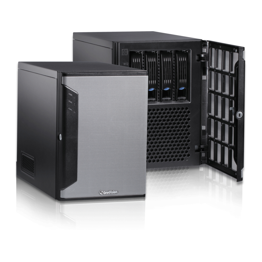
Overview Chapter 2 Overview 2.1 Front View Figure 2-1 No. Name Name 3.5” HDD Tray x 4 Not Functional Power Button Reset Button Power LED (Blue) USB 2.0 x 2 HDD Activity LED (Red) -
Page 14: Rear View
2.2 Rear View Figure 2-2 No. Name Name Power Connector USB 2.0 Port x 4 LFH Audio and Video Connector* VGA Monitor Output Audio Line In Port DVI-D Port Audio Line Out Port USB 3.0 Port x 2 Audio Microphone In Port HDMI Port Ethernet Port x 2 Not Functional... -
Page 15: Chapter 3 Getting Started
Getting Started Chapter 3 Getting Started 3.1 Basic Installation This section describes all the equipments required to program and operate the GV-Tower DVR/NVR/VMS System V2. Here we use GV-Tower DVR System V2 as the example. Figure 3-1 1. There are three ways to connect the monitor to the GV-Tower DVR/NVR/VMS System V2. •... - Page 16 4. Using the supplied LFH Audio and Video cable, connect the yellow ends to the cameras, and the red ends to the microphones. 5. Using the RJ-45 cable, connect one end to the Ethernet port and the other end to Network. 6.
-
Page 17: Using The Ir Remote Control
Getting Started 3.1.1 Using the IR Remote Control The GV-IR Remote Control provides easy control of the GV-Tower DVR/NVR/VMS System V2. Its receiver should be plugged into any USB ports of the system. For details, see GV-IR Remote Control User’s Manual (GV-Desktop > Program button > User Manual). -
Page 18: Connecting To 3 Monitors
3.1.2 Connecting to 3 Monitors You can connect the 3 monitors to the ports labeled below on the back panel of the GV-Tower DVR/NVR/VMS System V2. Here we use GV-Tower DVR System V2 as the example. Figure 3-3 To install other required equipment, follow the steps in 3.1 Basic Installation. -
Page 19: Installing The Hard Drive
Getting Started 3.2 Installing the Hard Drive The GV-Tower DVR/NVR/VMS System V2 uses SATA hard drives for video and audio data storage. Before recording, ensure to install your hard drives. Follow the below steps to install the hard drive. 1. Press the release latch. The drawer handle pops up. Release Latch Figure 3-4 2. - Page 20 4. Insert the hard drive in the drawer. Figure 3-6 5. Secure the hard drive with the 4 screws, and make sure all screw heads flush with the surface. Figure 3-7 6. Put the drawer back in the drive bay of the GV-Tower DVR/NVR/VMS System V2, and push the latch until it locks.
-
Page 21: Windows Setup Installation
Getting Started 3.3 Windows Setup Installation The Windows setup is preparing your computer for first use. 1. After the Windows starts, the following screen pops up. Select your language and click Next. Figure 3-9 2. Select your country or region, time and currency and keyboard layout. Then click Next. Figure 3-10... - Page 22 3. Type a user name for your account and then click Next to continue. Figure 3-11 4. It is recommended that you create a password for your account and then click Next to continue. Figure 3-12...
- Page 23 Getting Started 5. Since no license terms are specified, the page is left blank intentionally. Select I accept the license terms and click Next. Figure 3-13 6. You are suggested to select Ask me later to disable Windows automatic update. Selecting the other two options may generate temporary files and result in wasting the internal disk space.
- Page 24 7. Select your time zone, date and time and click Next. Figure 3-15 8. You are recommended to select Work network in the screen below to disable the network management share functions for security reasons. Figure 3-16 When the above setup process is complete, Windows will finalize your settings automatically in the background and restart.
-
Page 25: Formatting The Hard Drive
Getting Started 3.4 Formatting the Hard Drive After installing hard drives to your system, you will need to format them before use. 1. On the GV-Desktop, click the Programs button, and select Disk Management. Figure 3-17 2. Type the ID and password in the dialog box. The default ID and password are “0000”. Figure 3-18... - Page 26 3. Right-click in the unallocated space of a new drive, and select New Simple Volume. Figure 3-19 4. The New Simple Volume Wizard appears. Click Next to continue. Figure 3-20...
- Page 27 Getting Started 5. The default partition size is the same as the maximum disk space. Make changes if necessary. Click Next to continue. Figure 3-21 6. Assign a drive path that is not in use by other devices, and click Next to continue. Figure 3-22 Note: The default drive path starts from D:\.
- Page 28 7. Type a name in the Volume label box, ex. HDD1, and click Next to continue. Figure 3-23 8. When the formatting is complete, click Finish to close the wizard. Figure 3-24...
- Page 29 Getting Started 9. When the drive is successfully initialized, partitioned, and formatted, its status description should display “Healthy.” Figure 3-25...
-
Page 30: Adding The Hard Drive To The Recording Path
3.5 Adding the Hard Drive to the Recording Path For GV-Tower DVR/NVR/VMS System V2, you need to add the formatted hard drives to the recording path before recording. 3.5.1 GV-Tower DVR/NVR System V2 1. On the GV-Desktop, click the Programs button, and select Hot Swap HDD Tool. The MediaMan Tools window appears. - Page 31 Getting Started 3. If a hard drive is not inserted, follow these steps: A. Insert a hard drive or plug a USB hard drive to the GV-Tower DVR/NVR System V2. Figure 3-27 B. Select Add to recording path, and select the storage group from the drop-down list. Note: Storage 1 is the default storage group.
-
Page 32: Gv-Tower Vms System V2
3.5.2 GV-Tower VMS System V2 1. On the GV-VMS, click Home , select Toolbar , select Configure , select System Configure, and click Record Setting. This dialog box appears. Figure 3-29 2. Click the Arrow button next to Storage. This dialog box appears. Figure 3-30... - Page 33 Getting Started 3. To add a hard drive to the recording path, follow these steps: Figure 3-31 A. To add a new folder in the first storage group, click the Add button on the right pane and select a folder. Only 1 folder can be assigned as storage folder for each partition (e.g.
-
Page 34: Setting Up On-Screen Led Panel
3.6 Setting Up On-Screen LED Panel For GV-Tower DVR/NVR/VMS System V2, a LED panel on the screen provides a quick indication of the activity status of hard disk drives. Figure 3-32 LED Color Description - No HDD is assigned to this LED. Gray - The system is not started. - Page 35 LED Panel always stays on top: This option makes the LED panel stay on top of other windows when the Media Man Tools window is minimized. Synchronize the LED Panel with the LED Device on GV-Tower System V2: Not functional on GV-Tower DVR/NVR/VMS System V2.
-
Page 36: Replacing The Hard Drive
3.7 Replacing the Hard Drive You can replace the hard drive without shutting down the GV-Tower DVR/NVR/VMS System 1. Do not turn off the power before you replace the hard drive. 2. Push the release latch. The drawer handle pops up. 3. -
Page 37: Configuring The Ip Address
Getting Started 3.8 Configuring the IP Address GV-Tower DVR/NVR/VMS System V2 supports remote monitoring, control and configuration over a network connection. The following default IP addresses will automatically be assigned. • Connection 1: 192.168.0.200 • Connection 2: 192.168.0.201 • Default Subnet Mask: 255.255.252.0 The local area connections listed correspond to the Ethernet ports as shown below: Local Area Connection 2 Default IP: 192.168.0.201... - Page 38 To change the above default IP addresses, follow the steps below. 1. On the GV-Desktop, click the Programs button, and select Control Panel. Figure 3-35 2. Type the ID and password. The default ID and password are “0000”. The Control Panel window appears.
- Page 39 Getting Started 4. Under Connections, select the Local Area Connection you want to configure. Figure 3-37 5. Select Internet Protocol Version 4 (TCP/IPv4), and select Properties. Figure 3-38...
- Page 40 6. Select Use the following IP address and type the new IP information in the fields. Or select Obtain an IP address automatically to enable dynamic IP address. Figure 3-39 7. Click OK to finish the setting.
-
Page 41: Exiting To Windows
Getting Started 3.9 Exiting to Windows GV-Tower DVR/NVR/VMS System V2 are protected by GV-Desktop that is limited to run the selected programs. If you need to exit to Windows desktop, follow these steps. 1. Exit the main screen to display the GV-Desktop screen. •... -
Page 42: Returning To Gv-Desktop
3.10 Returning to GV-Desktop To return to GV-Desktop, click the Windows Start button, point to All Programs, click GV-DVR/NVR/VMS, and click Key Lock Utility. Figure 3-42... -
Page 43: Twin View Display
Getting Started 3.11 Twin View Display 3.11.1 GV-Tower DVR/NVR System V2 You can display live view and play back video in two separated monitors. 1. Follow Steps 1 and 2 in 3.8 Configuring the IP Address to access the Control Panel window. - Page 44 8. Click the Up button on the toolbar, go to the system folder and locate DMPOS.exe. Figure 3-44 9. Double-click DMPOS.exe. The Set Application Function Position dialog box appears. Figure 3-45 10. In the Screen Setup tab, select TwinView from the Displayer Mode drop-down list. 11.
-
Page 45: Gv-Tower Vms System V2
Getting Started 3.11.2 GV-Tower VMS System V2 You can customize the display settings of GV-VMS. Click Home , select Toolbar select Configure , select System Configure, and click Set Position. This dialog box appears. The right side of the dialog box is only available when multiple monitors are installed. Figure 3-46 •... -
Page 46: Digital Matrix
3.12 Digital Matrix To display multiple channels through two monitors, Digital Matrix is thus introduced to provide a method. The Digital Matrix includes these features: Live view: You can set different live views and screen divisions for each monitor. Automatic channel scan: You can set up to 16 scanned pages with different screen divisions and channels for each monitor. -
Page 47: Setting Live View
Getting Started 3.12.2 Setting Live View You can set different live views and screen divisions for each monitor. 1. On the main screen, click the Configure button, click Accessories, and select Digital Matrix Setting. This dialog box appears. Figure 3-48 2. -
Page 48: Setting Scanned
3.12.3 Setting Scanned Pages You can set up to 16 scanned pages with different screen divisions and channels for each monitor. 1. Use the Display list to select the monitor to be configured. 2. In the upper-left column, expand the Matrix folder tree, and click Page 1. This page appears. -
Page 49: Setting Pop-Up Alert
Getting Started 3.12.4 Setting Pop-up Alert You can be alerted by pop-up live videos when motion is detected or I/O devices are triggered. 1. Use the Display list to select the monitor to be configured. 2. In the upper-left column, click Event Popup. This page appears. Figure 3-50 Motion Trigger: The live video of selected cameras pops up when motion is detected. - Page 50 3.12.4.1 Setting Pop-up Positions When you select Random Position of Camera, you can decide the positions for pop-up cameras. Fixed Position of Camera: The cameras pop up in their assigned positions. To assign positions, select Screen Division. Then drag and drop the cameras number to the desired potions on the divisions.
-
Page 51: Setting Live View With Pop-Up Alert
Getting Started 3.12.5 Setting Live View with Pop-up Alert You can set a different live view mode with pop-up alert together for each monitor. When alert events occur, the live video of the associated camera will pop up on the assigned monitor to replace its live view mode. -
Page 52: System Restoration
3.13 System Restoration 3.13.1 Restoring System You can restore preinstalled files once they are damaged by running the recovery from the hidden partition. To restore the operating system and all preinstalled software, follow the steps below. Note: After recovery, you need to re-install all settings and passwords. But the recovery will not delete your recording files saved in the other partitions since it only reformats the partition 1. - Page 53 Getting Started 3. When the below screen appears, click the Recovery button. After recovery, click Quit and then OK to restart the Windows. Figure 3-52 For the recovery system part, see steps 1 ~ 8 in 3.3 Windows Setup Installation.
-
Page 54: Configuring Gv-Tower Dvr System V2 For Pal
3.13.2 Configuring GV-Tower DVR System V2 for PAL The default video standard after recovery is set to NTSC. If the video standard in your country is PAL, remember to configure the GV-Tower DVR/NVR System V2 for PAL after recovery. 1. Click the Configure button, point to A/V Setting, and then select Video Source. Figure 3-53 2. -
Page 55: Updating Gv-Tower System V2
Getting Started 3.14 Updating GV-Tower System V2 If you like to update your GV-Tower DVR/NVR/VMS System V2, contact your dealer for more information. Before contacting your dealer, you may check software update news at our website: http://www.geovision.com.tw... -
Page 56: Chapter 4 Nvr Health Analysis
Chapter 4 Health Analysis GeoVision offers health analysis to GV-Tower DVR/NVR/VMS System V2. The service is intended to give diagnosis for early and immediate detection of problems. It is recommended to have the health analysis during the first week after you install the GV-Tower DVR/NVR/VMS System V2, and then have the checkup every three months. - Page 57 Health Analysis 2. Select Backup MultiCam Settings or Restore Defaults, and select Backup Current System. This dialog box appears. Figure 4-2 3. Press the Next Step button to back up all your system settings. The Save As dialog box appears. 4.
-
Page 58: System Log
4.2 System Log Please provide the sys*.mdb files of system log. The files by default are saved at C:\GV folder\database (GV-Tower DVR/NVR System V2), or C:\Log\Database (GV-Tower VMS System V2). If you have modified the default location, you can check the path by the following steps: 1. -
Page 59: Information Of Your Computer System
Health Analysis 4.3 Information of Your Computer System To get the information of your computer system, please follow the steps below to install the free software PC WIZARD. By using the software, the following computer information can be easily collected and saved for analysis: Processor: includes Type, Frequency, Data Cache L1, Trace Cache L1, Cache L2, Voltage, Processor Temperature, FPU Coprocessor. - Page 60 4. In the Save As dialog box, select Format HTML and click OK. Figure 4-5 5. Select the Save location, type the file name, and then click Save to save the Processor information as HTML file. 6. Repeat Steps 3-5 to save the Drives information as HTML file.
-
Page 61: Health Analysis Form
Health Analysis 4.4 Health Analysis Form Please send the related data for analysis along with this Health Analysis Form to dvrsystem@geovision.com.tw. Health Analysis of GV-Tower DVR/NVR/VMS System V2 Contact Person: Title: Company Name: Telephone: (O) Fax: E-Mail: Model: Bar Code: 4.5 Check List... -
Page 62: Chapter 5 Troubleshooting
Chapter 5 Troubleshooting GV-Tower DVR/NVR/VMS System V2 stops responding (aka “crashed” or “froze”). If your GV-Tower DVR/NVR/VMS System V2 is not responding to your clicking, typing, or mouse movements, try these steps to get your GV-Tower DVR/NVR/VMS System V2 back on track. - Page 63 Troubleshooting GV-Tower DVR/NVR/VMS System V2 hard disk corrupts. If you are experiencing file system corruption problems, such as lost clusters, cross-linked files or invalid files or directories, try these steps: 1. Use the HD Tune utility to scan the hard disk for errors. Follow these steps: A.
- Page 64 2. If the HD Tune utility does not find any defects, use the Windows built-in utility to attempt to fix the errors. Follow these steps: A. On the GV-Desktop, click the Programs button, and select Disk Management. See Figure 3-9. B.
- Page 65 2. Make sure the camera and its cable are not damaged or frayed. Try to replace a camera or camera cable to see if this fixes the problem. How can I find more help? 1. Visit our website at http://www.geovision.com.tw/english/4_1.asp 2. Write us at dvrsystem@geovision.com.tw...
-
Page 66: Specifications
Specifications GV-Tower DVR/NVR/VMS System V2 Hardware System Intel Core i3 Processor Intel Core i5 Processor (optional) 4 GB Dual Channels 4 (3.5” HDD) No. of HDD 64 GB SSD Internal Storage 64-bit Windows Embedded OS DirectX 250 W, 110-115 V, 60 Hz Power 250 W, 220-230 V, 50 Hz RJ-45, 10 / 100 / 1000 Mbps x 2... - Page 67 Video Input (license required) 32 channels in increments of 1 channel 32 channels Audio Input (license required) Note: It is required to enable the dual-stream function on GeoVision and third-party IP cameras to have the maximum number of channels supported.
- Page 68 Mobile device (Android Smartphone and tablet; iPad, iPhone Environment and iPod Touch) Max. 32–channel multi views, up to 200 channels connection to Live View GV-Tower System V2 LAN, WAN, Internet Network Type System Monitoring and Recovery Automatic restart after power outage...
- Page 69 Specifications Language Model GV-Tower DVR/NVR System V2 GV-Tower VMS System V2 Arabic / Bulgarian / Czech / Danish Bulgarian / Czech / Danish / Type / Dutch / English / Finnish / French English / French / German / / German / Greek / Hebrew / Greek / Hebrew / Hungarian / Hungarian / Indonesian / Italian / Italian / Japanese / Persian /...
-
Page 70: Appendix
Appendix A. Hard Disk Requirements The total of recording frame rates that you can assign to a single hard disk is listed as below: Frame rate limit in a single hard disk when connecting to analog cameras Analog Cameras / SW Compression MPEG4 Video Resolution NTSC... -
Page 71: B Total Frame Rate And Max. No. Of Channels Supported
Appendix B. Total Frame Rate and Max. No. of Channels Supported Below are the total frame rates GV-Tower DVR/NVR/VMS System V2 can support with CPU usage of approximately 70% to ensure performance and stability. You could connect up to 32 cameras to the system. - Page 72 For GV Fisheye Cameras (Single Stream De-warping) • GV-Tower DVR/NVR System V2 Intel Core i3 Intel Core i5 Video Single Stream Max. FPS Full-Frame Full-Frame Resolution (H.264) Total FPS Total FPS Channels Channels 1.3 MP 1280 x 1200 15 fps 180 fps 12 ch 180 fps...
-
Page 73: C Supported Ip Devices
Appendix C. Supported IP Devices This list provides the supported IP device brands. For detailed information on the supported IP devices, refer to Supported IP Camera List on GeoVision’s Website: http://www.geovision.com.tw/english/4_21.asp GeoVision ACTi Arecont Vision AXIS Bosch Canon D-Link Etrovision... -
Page 74: Warranty Requirements
To validate your purchase, you shall complete the online Product Registration within 30 days from the date of purchase at http://www.geovision.com.tw/english/4_6.asp. Or click GeoVision Online Registration in My Favorite for a direct link. If you fail to complete the Product Registration, the warranty period will start from the date of shipment. - Page 75 2. Securely pack the product in its original carton using the original packing material, or in equivalent packaging. 3. The product shall be returned to GeoVision, Taiwan at your expense for shipping and insurance costs. BEFORE YOU DELIVER YOUR GV-TOWER DVR/NVR/VMS V2 SYSTEM FOR WARRANTY SERVICE, IT IS YOUR RESPONSIBILITY TO BACK UP YOUR DATA.
-
Page 76: Warranty Form
GeoVision Online Registration in My Favorite for a direct link to register online within 30 days from the date of purchase. Please keep this copy for your records. - Page 77 Warranty Form Bar Code: Shipment Date: GeoVision, Inc. 9F, No. 246, Sec. 1, Neihu Rd., Neihu District, Taipei, Taiwan Tel: +886-2-8797-8377 Fax: +886-2-8797-8335 Email: sales@geovision.com.tw dvrsystem@geovision.com.tw http://www.geovision.com.tw...
Need help?
Do you have a question about the GV-Tower System V2 and is the answer not in the manual?
Questions and answers