Advertisement
Table of Contents
- 1 Table of Contents
- 2 15. Appendix
- 3 Safety Instructions
- 4 Safety Label Locations
- 5 Specifications
- 6 Component Identification
- 7 Troubleshooting
- 8 Pre-Operation Check
- 9 Starting the Engine
- 10 High Altitude Operation
- 11 Generator Use
- 12 Double Generators Parallel
- 13 Stopping the Engine
- Download this manual
Advertisement
Table of Contents

Related Manuals for Kipor Sinemaster IG200


Summary of Contents for Kipor Sinemaster IG200
- Page 1 WUXI KIPOR POWER CO., LTD. S I N E M A S T E R DIGITAL INVERTER GENERATOR I G 2 0 0 0 I G 2 0 0 0 s I G 2 0 0 0 p...
- Page 3 PREFACE Thank you for purchasing our generators. This manual covers operation and maintenance of the IG2000, IG2000s, IG2000p generator. All information in this publication is based on the latest product information available at the time of approval for printing. We reserve the right to make changes at any time without notice and without incurring any obligation.
-
Page 4: Table Of Contents
CONTENTS 15. APPENDIX 1. SAFETY INSTRUCTIONS Modified coefficient table of ambient condition power 2. SAFETY LABEL LOCATIONS 3. COMPONENT IDENTIFICATION The conditions of generator rated output: Altitude: 0 m Ambient temperature: 25 Relative humidity: 30% 4. PRE-OPERATION CHECK Ambient modified coefficient: C (Relative humidity 30%) 5. -
Page 5: Safety Instructions
14. LIGHT KIT 1. SAFETY INSTRUCTIONS MOUNTING INSTRUCTIONS FOR: IG2000s LIGHT KIT To ensure safe operation M5 Nut WARNING The generators are designed to give safe and depend- M5 65 able service if operated according to instructions. Read and understand the Owner's Manual before op- erating the generator. - Page 6 SAFETY INSTRUCTIONS To ensure safe operation WARNING Gasoline is extremely flammable and explosive under certain conditions. Refuel in a well ventilated area with the engine stopped. Keep away from cigarette, smoke and sparks when refueling the generator, Always refuel in a well-ventilated location. Wipe up spilled gasoline at once.
-
Page 7: Safety Label Locations
13. ELECTRICAL WIRING DIAGRAM 2. SAFETY LABEL LOCATIONS These lables warn you potential hazards that can cause serious injury. Read the labels and safety notes and precautions described in manual carefully. If a label comes off or becomes hard to read, contact your dealer for a replacement. -
Page 8: Specifications
12. SPECIFICATIONS SPECIFICATIONS IG2000/IG2000s/IG2000p Model Rated frequency (Hz) Rated voltage (V) MODEL Rated current (A) 13.3 Rated speed (rpm) 4500 HOT CAUTION Rated output (kVA) Max. output (kVA) DC output DC voltage 12V-8.3A Electric circuit breaker Available SAFETY CAUTION Single phase Phase number Engine Model Type... -
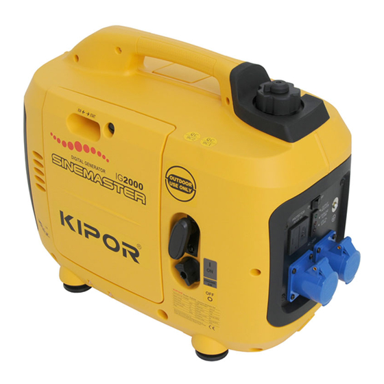
Page 9: Component Identification
Appliance does not operate: 3. COMPONENT IDENTIFICATION Is the output indicator light ON? FUEL CAP HANDLE CHOKE HANDLE Is the overload in- FUEL FILLER CAP Take the generator to an dicator light ON? authorized dealer. MAINTENANCE COVER CONTROL PANEL Check the electrical appli- NO DEFECTS Take the generator to an ance or equipment for any... -
Page 10: Troubleshooting
Control panel 11. TROUBLESHOOTING EU type When the engine will not start: SMART-THROTTLE SWITCH Is there fuel in the tank? Refuel the fuel tank OUTPUT INDICATOR LIGHT OVERLOAD INDICATOR LIGHT Is the engine switch on? Turn the engine switch on. DC RECEPTACLE Is the enough oil in the engine? Add the recommended oil. - Page 11 A type (120V) Aus type a. Drain all gasoline from the fuel tank into an approved gasoline container. b. Turn the engine switch ON, and loosen the carburetor drain screw and drain the gasoline from the carburetor into a suitable container. c.
- Page 12 Smart throttle 10. TRANSPORTING STORAGE Engine speed is kept at idle automatically when the electrical appliance is disconnected and it returns to the proper speed to power of the electrical load when electrical appliance is connected. This position is recommended to minimize the fuel consumption while in operation.
-
Page 13: Pre-Operation Check
3.Use a brush to remove carbon deposits from the spark arrester screen. 4. PRE-OPERATION CHECK Inspect the screen for holes, and replace it if necessary. WARNING Be sure to check the generator on a level surface with the engine stopped. 1. - Page 14 4.SPARK ARRESTER MAINTENANCE(Equipped type only) NOTE: The Low Oil Alarm System will automatically stop the engine before the oil level falls below the safe limit. However, to avoid the inconvenience of an unexpected shutdown, it is still advisable to visually inspect the oil level regularly. WARNING If the generator has been running, the muffler will be very hot.
- Page 15 5. Visually inspect the spark plug. Discard it if the insulator is cracked or chipped. Fuel tank capacity: 3.7 liter (0.97 US gal, 0.81 lmp gal) Clean the spark plug with a wire brush if it is to be reused. 6.
- Page 16 3. SPARK PLUG SERVICE 3. Check the air cleaner. RECOMMENTDED SPARK PLUG: BOSCH R6 SUF Check the air cleaner element to be sure it is clean and in good condition. Loosen the cover screw and remove the left side maintenance cover. To ensure proper engine operation, the spark plug must be properly gapped and free of Press the latch tab on the top of the air cleaner body, remove the air cleaner cover, check deposits.
-
Page 17: Starting The Engine
2. AIR CLEANER SERVICE 5. STARTING THE ENGINE A dirty air cleaner will restrict air flow to the carburetor. T o prevent carburetor malfunc- tion, service the air cleaner regularly. Service more frequently when operating the generator in extremely dirty areas. Before starting the engine, disconnect any load from the AC receptacle. - Page 18 3. Move the choke handle to the START position. 1. CHANGING OIL NOTE: Do not use the choke when the engine is warm or the air temperature is high. Drain the oil while the engine is still warm to assure rapid and complete draining. CAUTION Make sure to turn the engine switch and the fuel cap vent lever OFF before draining.
- Page 19 5.Move the choke handle to the RUN position after the engine warms up. 9. MAINTENANCE CHOKE HANDLE The purpose of the maintenance and adjustment schedule is to keep the generator in the best operating condition. Inspect or service as scheduled in the table below. WARNING Shut off the engine before performing any maintenance.
-
Page 20: High Altitude Operation
High altitude operation WARNING: The special parallel cable for our IG2000p is only applicable to the parallel operation At high altitude, the standard carburetor air-fuel mixture will be excessively rich. of two IG2000p generators. It can not be used for paralleling three or above three Performance will decrease, and fuel consumption will increase. -
Page 21: Generator Use
5. Start the twin generators (engines) and confirm that both generators started. The 6. GENERATOR USE starting procedure is same as the normal starting procedure. (See"STARTING THE ENGINE"of the operation manual.) Note: Confirm the bellows before starting the both generators. (1). - Page 22 Parallel operation features: CAUTION Two pieces of our IG2000p can be paralleled to increase the total Do not exceed the rated power. output. The total wattage of all appliances connected must be considered. Do not exceed the current limit specified for any one receptacle. Parallel operation procedure: Do not connect the generator to a household circuit.
-
Page 23: Double Generators Parallel
AC applications DOUBLE GENERATORS PARALLEL (Limited to the 1. Start the engine and make sure only the output indicator light (green) comes on. IG2000p has parallel function) 2. Confirm that the appliance to be used is switched off, and plug in the appliance. OUTPUT INDICATOR LIGHT OVERLOAD INDICATOR Control panel... - Page 24 Output and Overload Indicators 3. Allow the engine to cool well, and turn the fuel cap lever fully counterclockwise to the OFF position. The output indicator light(green) will remain ON during normal operating conditions. If the generator is overloaded (in excess of 1.6KVA), or if there is a short in the FUEL CAP LEVER connected appliance, the output indicator light (green) will go OFF, the overload indicator light (red) will go ON and current to the connected appliance will be shut off.
-
Page 25: Stopping The Engine
DC application 7. STOPPING THE ENGINE The DC receptacle may be used for charging 12 volt automotive-type batteries only, the zero load voltage is 15V-30V. NOTE To stop the engine in an emergency, turn the engine switch to the OFF position. In DC operation, turn the Smart-throttle switch to the OFF position. - Page 26 Low oil alarm system WARNING The low oil alarm system is designed to prevent engine damage caused by an The battery gives off explosive gases; keep spark, flames and cigarettes away. insufficient amount of oil in the crankcase. Before the oil level in the crankcase falls Provide adequate ventilation when charging.
Need help?
Do you have a question about the Sinemaster IG200 and is the answer not in the manual?
Questions and answers