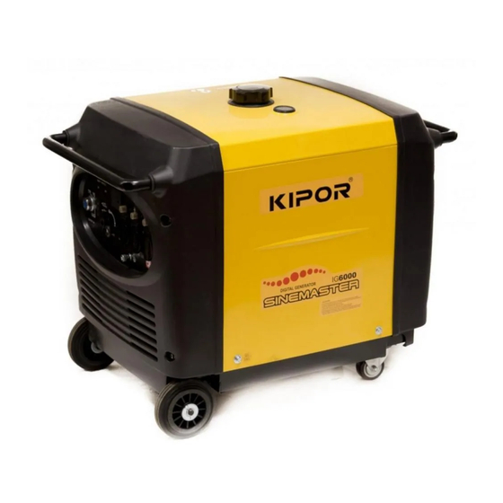
Kipor Sinemaster IG6000 Operation Manual
Gigital generator sinemaster
Hide thumbs
Also See for Sinemaster IG6000:
- Service manual (52 pages) ,
- Owner's manual (43 pages) ,
- Operation manual (18 pages)
Table of Contents
Advertisement
Advertisement
Table of Contents

Related Manuals for Kipor Sinemaster IG6000


Summary of Contents for Kipor Sinemaster IG6000
-
Page 2: Preface
PREFACE Thank you for purchasing a Kipor Generator. This manual covers the operation and preventive maintenance of the IG6000 and IG6000H generator with EPA and California Air Resources Board (CARB) certification if so designated. All information in this publication is based on the latest product information available at the time of printing. - Page 3 Always stop engine before refueling. Wait 5 minutes before restarting. Keep any source of ignition away from the fuel tank at all times. he portable generator is not meant to be used as a permanent back-up power system for the home. A permanently installed stationary generator is designed to be safely used for this specific purpose.
-
Page 4: Table Of Contents
CONTENTS REFACE ............................1 TENTS ........................... 3 . SAFETY INSTRUCTIONS ......................5 . COMPONENT LOCATIONS ...................... 8 2.1 Exterior View ........................8 2.2 Inlet System .......................... 9 2.3 Exhaust System ........................9 2.4 CARB Evaporative Control System ..................10 2.5 Carbon Canister ........................11 2.6 Control Panel ........................ - Page 5 8. TRANSPORTING/STORAGE ....................36 9. TROUBLESH OOTING ......................37 10. S PECIFICATIONS ........................ 39 11. W IRING DIAGRAM ........................ 40 12. W HEEL KIT .......................... 41 12.1 IG6000 ..........................41 12.2 IG6000H ......................... 42 - 4 -...
-
Page 6: Safety Instructions
1. SAFETY INSTRUCTIONS ■ Our generators are designed to give safe and dependable service if operated according to these instructions. Read and understand the owner's manual before operating the generator. Failure to do so could result in personal injury or equipment damage. ■Exhaust gas contains poisonous carbon monoxide. - Page 7 To ensure safe operation: ■Gasoline is extremely flammable and explosive under certain conditions. Refuel in a well ventilated area with the engine stopped. ■Keep away from smoking materials, sparks and other sources of combustion when refueling the generator. Always refuel in a well-ventilated location. ■Wipe up spilled gasoline at once.
- Page 8 ■Never operate the generator with the door open or any panels removed. Do not operate in any enclosure such as an RV compartment. ■Keep away from rotating parts while the generator is running. ■The generator is a potential source of electrical shocks when misused;...
-
Page 9: Component Locations
2. COMPONENT LOCATIONS 2.1 Exterior View 火花塞... -
Page 10: Inlet System
2.2 Inlet System Air filter shell 空气滤清器底 壳 Fixed bracket 滤芯固定 架 Seal gaske 密封垫 滤芯 Filter element Air filter cover 空气滤清器盖 螺母 Carburetor 化油器部件 2.3 Exhaust System haust System 二次补气阀组件 Secondary air injection valve Bolt 螺栓 Spark Arrestor 防火帽组件 Muffler assembly Muffler ... -
Page 11: Carb Evaporative Control System
2.4 CARB Evaporative Control System Fuel cap 油箱盖总成 Fuel tank cover 油箱盖 Threaded sleeve 油箱盖内螺纹套 Pallet 油 箱盖内 棘爪 Cotter pin Bushing 开口销 油箱盖内称套 垫圈 加油口过滤网 Washer Filter screen 油箱盖内垫片 Gasket Hook Certificate No. 防掉倒钩 材 料和证书编 号 Fuel tank X6800BM 油箱... -
Page 12: Carbon Canister
2.5 Carbon Canister Location (CARB only) 碳 罐 固 定 皮 带 Bracket 大 气 弯 管 Curved hose 碳 罐 Carbon Canister 油 箱 通 气 管 Vent hose 碳 罐 负 压 管 - 11 -... -
Page 13: Control Panel
2.6 Control Panel GFCI Receptacle 120V 30A Receptacle Choke Handle 120/240V 30A Receptacle DC Receptacle .6 Con trol panel Smart Throttle 交流插座 GFCI Receptacle 120V 30A Receptacle Indicator 交流插座 阻风门手柄 Choke Handle 交流插座 120/240V 30A Receptacle DC Receptacle 直流插座 Smart Throttle 智能节气门... -
Page 14: Pre Operation Check
3. PRE-OPERATION CHECK Be sure to check the generator on a level surface with the engine stopped. 3.1 Check the engine oil level WARNING ■ Using non detergent or 2-stroke eng ine oil could shorten the engine's service life. ■ Use a high-detergent, premium quality four cycle engine oil, certified to meet or exc U.S. -
Page 15: Fuel Level
CAUTION ■Running the engine with insufficient oil can cause serious engine damage. ■The oil Alert System will automatically stop the engine before the oil level fal ls below the safe limit. However, to avoid the inconvenience of an unexpected shutdown, it is still advisable to visually inspect the oil level before each use. -
Page 16: Air Cleaner
GASOLINES CONTAINING ALTERNATE FUELS If you decide to use a gasoline containing ethanol be sure its octane rating is no lower than the specification. Do not use a blend that contains more than 10% ethanol. Do not use gasoline containing methanol. .3 Check the air cleaner heck the air cleaner elements to be sure they are clean and in good condition. -
Page 17: Starting The Generator
4. STARTING THE GENERATOR CAUTION ■ When starting the generator after adding fuel for the first time, after long-term storage, or after running out of fuel, turn the fuel valve lever to the "ON" position then wait 10 to 20 seconds before starting the engine. a. - Page 18 c. Insert the engine key and turn the ignition switch to ON position. 关 开 开始 START 发动机开关 Ignition switch 图 9 起动旋钮工作位置图 d. Turn the ignition switch to the START until the engine starts. 关 开 START 开始 Engine switch 发动机开关...
- Page 19 4.5 Push the choke knob to the OPEN position as the engine warms up Choke Knob 阻风门开关 igh altitude operation t high altitude, the standard carburetor air-fuel mixture will be excessively rich erformance will decrease, and fuel consumption will increase. igh altitude performance can be improved by installing a smaller diameter ain fuel jet in the carburetor..
-
Page 20: Generator Use
5. GENERATOR USE WARNING ■To prevent electrical shock from faulty appliances, the generator should be grounded. Connect a length of heavy wire between the generator's ground terminal and an external ground source. Ground Terminal 接地端 CAUTION ■ Limit operation requiring maximum power to 30 minutes. For continuous operation do not exceed the rated power. - Page 21 NOTE ■You may use DC receptacle when using AC supply. ■If you want to use AC and DC receptacle simultaneously, the total output should not be over the sum output of AC and DC. ■Electrical equipment containing the wiring and plug should not have defect. Control panel 交流插座...
-
Page 22: Ac Power Application
5.1 AC Application 1. Start the engine and make sure the green output ind icator light comes on. 2. Confirm that the appliance to be used is s witched off and plug in the appliance. CAUTION ■ Be sure that all appliances are in good working order before connecting them to the generator. -
Page 23: Output And Overload Indicators
5.2 Output and Overload Indicators he green output indicator light will remain ON during normal operating conditions. If the generator is overloaded or if there is a short in the connecte appliance the output indicator will go OFF and the overload indicator will go ON and cu rrent to the connected appliance will be shut off. -
Page 24: Voltage Selection Switch
The two 120V receptacles are rated at 20 and 30 amps respectively.Should this current be exceeded, the circuit protection device willactivate and cut allcurrent to the receptacle. This will be indicated by the push button popping out. Reduce the load to the receptacle and reset the circuit protector by pushing in the button. -
Page 25: Smart Throttle
.4 Smart Throttle When the SMART thro ttle is placed in the on position, engine speed is kept at le automatically when the electrical load is disconnected and returns to the roper speed required by the electrical load when the load is reconnected. The ngine speed varies according to the amount of load applied to the generator. -
Page 26: Dc Power Application
a start capacitor as an extra cost option. The lack of a start capacitor can cause the air conditi oner to draw too high a starting current and overload the enerator. Contact your air conditioner dealer if you consistently have roblems starting your air conditioner with the generator. - Page 27 ■The battery gives off explosive gases: keep sparks, flames and cigarettes away. Provide adequate ventilation when charging. ■The battery contains sulfuric acid (electrolyte). Contact with skin or eyes may cause severe burns. Wear protective clothing and a face shie A. If electrolyte gets on your skin, flush with water. B.
-
Page 28: Stopping The Generator
6. STOPPING THE GENERATOR To stop the engine in an emergency, turn the engine switch OFF. In normal use: 1. Switch off the connected equipment and pull the plug from the receptacle. 2. Turn off the ignition swit 3. Turn the fuel valve lever to the OFF position. -
Page 29: Maintenance
Carbon monoxide is a poisonous gas. The emission of fuel vapors is a source of pollution as well. The Kipor generator engine utiliz es a precise air-fuel ratio and emission control ystem to reduce the emissions of carbon monoxide, NO , hydrocarbons, and vaporative fuel emissions. - Page 30 Kipor have been manufactured to the same production standard as the original parts. The use of replacement parts or accessories which are not designed by Kipor may affect the engine emission performance. The manufacturers of replacement parts and accessories have the responsibility to guarantee that their replacement products will not adversely affect emission performance.
- Page 31 Air Quality Index (only for California certified models) ARB requires that an air quality index label be attached to every certified ngine showing the engine emission information for the emission duration period. The label is provided for the user to compare the emission erformance of different engines.
-
Page 32: Maintenance Schedule
7.2 Maintenance Schedule OTE: (1) Log hours of operation to determine proper maintenance. (2) Service more frequently when used in dusty areas. (3) These items should be serviced by an authorized dealer unless the owner has the proper tools and is mechanically proficient. See the service manual. -
Page 33: Air Cleaner Service
1. Open the left side maintenance cover. . Take out the oil outlet plug. . Remove the drain bolt, and drain the oil. Retighten the bolt securely. . Refill with the recommended oil and check the level. 5. Close the left side maintena nce cover. -
Page 34: Spark Plug Service
7.5 Spark Plug Service Recommended spark plug: WR7DC To ensure proper engine operation, the spark plug must be properly gapped nd free of deposits. 1. Open the left side maintenance c over. 2. Remove the spark plug cap. Spark plug wrench Fig, 15 Spark plug 3. - Page 35 Spark plug clearance 0.7-0.8 火花塞间隙 CAUTION ■ The spark plug must be securely tightened. An improperly tightened plug an become very hot and possibly damage the generator. Never use a spark plug with an improper heat range. ■ 7. Install the spark plug carefully, by hand, to avoid cross-threading. .
-
Page 36: Spark Arrestor Maintenance
7.6 Spark Arrestor Maintenance Secondary gulp valve 二次补气阀 Spark arrester 火星捕捉器 Rear cover 后面罩 Fig, 17 WARNING ■ If the generator has been running, the muffler will be very hot. Allow it to cool before proceeding. CAUTION ■ The spark arrester must be serviced every 100 hours to maintain its efficiency. -
Page 37: Transporting/Storage
8. TRANSPORTING/STORAGE . When transporting the generator, turn the fuel valve lever OFF and keep the enerator level to prevent fuel spillage. Fuel vapor or spilled fuel may ignite. o not transport the generator in a vehicle with fuel in the tank. b. -
Page 38: Troubleshooting
1) Turn off the fuel valve and loosen the d rain screw. 2) Fuel should flow from the drain when the fuel If the engine still does not start, take valve is turned on. the generator to an authorized Kipor service center. - 37 -... - Page 39 AC appliance does not operate: Is the output indicator light ON? Is the overlo ad indicator Take the generator to a Kipor light ON? service center. Check the electrical appliance or Take generator equipment for any defects. authorized KIPOR service center ■...
-
Page 40: Specifications
5.8gal.(22L) Continuous running time at rated 7.5 Hours output Nois e level(zero load~ full load) @ 23' 64-65 decibels (7M) Overall dimension (L×W×H) in. (mm) IG6000 : 31.6×19.5×24.6 (802×495×624) IG6000 h: 48.6× 25.59×30.3 (1235×650×770) Dry w eight –lbs (kg) 6000... -
Page 41: Wiring Diagram
11. WIRING DIAGRAM... -
Page 42: Wheel Kit
12. WHEEL KIT 12.1 IG6000 1. Washer 4. Wheel 3. Lock pin 4. Locking s wivel wheel 5. Bolt M6X16 To install the front wheels, inst all a w asher on the axle, then the wheel, another washer and secure with a wheel clip. -
Page 43: Ig6000H
12.2 IG6000H 1. IG6000H Chassis- installed 5. 10” Wheel 2. Support Bracket- (4) 6. Wheel Washer (4) 3. Front Stabilizer (2) 7. Wheel Clip 4. Axle Assembly ssembly: 1. Install the four support brackets and secure with bolts. 2. Attach the front stabilizers to the chassis (below the handles) 3.
Need help?
Do you have a question about the Sinemaster IG6000 and is the answer not in the manual?
Questions and answers