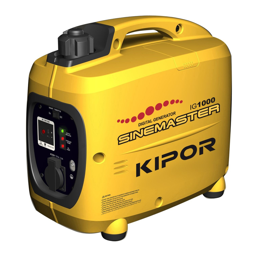
Kipor SINEMASTER IG1000 Operation Manual
Sinemaster
Hide thumbs
Also See for SINEMASTER IG1000:
- Shop manual (75 pages) ,
- Operation manual (54 pages) ,
- Operation manual (22 pages)
Advertisement
Table of Contents
- 1 Table of Contents
- 2 Safety Instructions
- 3 Safety Label Locations
- 4 Component Indentificaction
- 5 Pre-Operation Check
- 6 Starting the Engine
- 7 Generator Use
- 8 Stopping the Engine
- 9 Maintenance
- 10 Transporting/Storage
- 11 Troubleshooting
- 12 Specifications
- 13 Light Kit
- 14 Coast Distribution Warranty
- Download this manual
Advertisement
Table of Contents

Related Manuals for Kipor SINEMASTER IG1000


Summary of Contents for Kipor SINEMASTER IG1000
- Page 2 PREFACE Thank you for purchasing a Kipor generator. This manual covers the operation and maintenance of the Coast Distribution model IG1000 and IG1000s generators. All information in this publication is based on the latest product information available at the time of approval for printing.
- Page 3 NOTE: Gives helpful information. If a problem should arise or if you have any questions about the generator, consult an authorized dealer. Our generators are designed to give safe and dependable service if operated according to instructions. Read and understand the Owner's Manual before operating the generator. Failure to do so could result in personal injury or equipment damage.
-
Page 4: Table Of Contents
CONTENTS 1. SAFETY INSTRUCTIONS......................4 2. SAFETY LABEL LOCATIONS....................6 3. COMPONENT INDENTIFICACTION ..................7 4. PRE-OPERATION CHECK ......................9 5. STARTING THE ENGINE......................13 6. GENERATOR USE........................16 7. STOPPING THE ENGINE ......................24 8. MAINTENANCE ........................26 9. TRANSPORTING/STORAGE ....................33 10. -
Page 5: Safety Instructions
1. SAFETY INSTRUCTIONS ■Our generators are designed to give safe and depend-able service if operated according to instructions. Read and understand the Owner's Manual before operating the generator. Failure to do so could result in personal injury or equipment damage. ■Exhaust gas contains poisonous carbon monoxide. - Page 6 To ensure safe operation— ■ Gasoline is extremely flammable and explosive under certain conditions. Refuel in a well ventilated area with the engine stopped. ■Keep away from cigarette, smoke and sparks when re-fueling the generator. Always refuel in a well-ventilated location. ■...
-
Page 7: Safety Label Locations
2. SAFETY LABEL LOCATIONS These labels warn you of potential hazards that can cause serious injury. Read the labels and safety notes and precautions described in this manual carefully. If a label comes off or becomes hard to read, contact your dealer for a replacement. -
Page 8: Component Indentificaction
3. COMPONENT IDENTIFICATION... - Page 9 Serial number and bar code identification and location The generator serial number identifies your particular unit and is important when ordering parts and accessories. The bar code is used by your dealer and Coast Distribution for warranty administration. The serial number can be found stamped on the engine block above oil dipstick.
-
Page 10: Pre-Operation Check
4. PRE-OPERATION CHECK ■ Be sure to check the generator on a level surface with the engine stopped. 1. Check the engine oil level. ■ Using non detergent oil or 2-stroke engine oil could shorten the engine's service life. Use high-detergent, premium quality 4-stroke engine oil, certified to meet or exceed U.S.automobile manufacturer's requirements for API Service Classification SG,SF. - Page 11 NOTE: The Low Oil Alarm System will automatically stop the engine before the oil level falls below the safe limit. However, to avoid the inconvenience of an unexpected shutdown, it is still advisable to visually inspect the oil level regularly. 2.
- Page 12 Gasoline containing alternate fuels If you decide to use a gasoline containing ethanol, be sure its octane rating is equal to the specification. Do not use a blend that contains more than 15% ethanol. Do not use gasoline containing methanol. ■...
- Page 13 ■Turn the fuel cap lever to "OFF" position before transporting.
-
Page 14: Starting The Engine
5. STARTING THE ENGINE Before starting the engine, disconnect any loads from the AC and DC terminals. 1. Turn the fuel cap lever fully clockwise to the ON position. - Page 15 ■ Do not use the choke when the engine is warm or the air temperature is high. 4. Pull the starter grip until resistance is felt then pull the starter grip briskly toward the arrow as shown below. ■ Do not allow the starter grip to snap back, return it slowly by hand. 5.
- Page 16 High altitude operation At high altitude, the standard carburetor air-fuel mixture will be excessively rich. Performance will decrease, and fuel consumption will increase. High altitude performance can be improved by installing a smaller diameter main fuel jet in the carburetor. If you always operate the generator at altitudes higher than 5000 feet (1500 m) above sea level, have your authorized dealer install the high altitude main jet.
-
Page 17: Generator Use
6. GENERATOR USE ■To prevent electrical shock from faulty appliances, the generator should be grounded. Connect a length of heavy wire between the generator's ground terminal and an external ground source. ■ Connections for standby power to a building's electrical system must be made by a qualified electrician and must comply with all applicable laws and electrical codes. - Page 18 ■The DC receptacle can be used while the AC power is in use. If you use both at the same time, be sure not to exceed the total power for AC and DC. ■Most appliance motors require more than their rated watt-age for start-up.
- Page 19 Output and Overload Indicators The output indicator light (green) will remain ON during normal operating conditions. If the generator is overloaded (in excess of 1.0kVA), or if there is a short in the connected appliance, the output indicator light (green) will go OFF, the overload indicator light (red) will go ON and current to the connected appliance will be shut off.
- Page 20 1. Connect the ground terminal. 2. Start each engine according to "STARTING THE ENGINE". When the output indicator light (green) does not light and the overload indicator light (red) lights instead, set the engine switch to STOP, stop the engine at once and then start the engine again. 3.
- Page 21 4.Switch on the equipment to be used. In case of overload operation or when trouble occurs for the equipment being used, the output indicator light (green) will go out, the overload indicator light(red) will light continuously, and no power will be put out. At this time, the engine will not stop, so that the engine must be stopped by setting the respective engine switch to STOP.
- Page 22 The DC receptacle may be used for charging 12 volt automotive-type batteries only, the zero load voltage is 15V-30V. ■ In DC operation, turn the Smart throttle switch to the OFF position. 1.Connect the charging cables to the DC receptacle of the generator and then to the battery terminals.
- Page 23 ■The battery gives off explosive gases; Keep sparks flames and cigarettes away. Provide adequate ventilation when charging. ■The battery contains sulfuric acid (electrolyte). Con-tact with skin or eyes may cause severe burns. Wear protective clothing and a face shield. -If electrolyte gets on your skin, flush with water. -If electrolyte gets in your eyes, flush with water for at Least 15 minutes and call a physician.
- Page 24 Smart throttle Engine speed is kept at idle automatically when the electrical load is disconnected and returns to the proper speed to match the power of the electrical load when the load is reconnected. This position is recommended to minimize fuel consumption while in operation. ■...
-
Page 25: Stopping The Engine
7. STOPPING THE ENGINE To stop the engine in an emergency, turn the engine switch to the OFF position. IN NORMAL USE: 1. Switch off the connected equipment and pull the inserted plug. 2. Turn the engine switch to the OFF position. - Page 26 3. Turn the cap lever fully counterclockwise to the "OFF" position. ■Be sure the fuel cap lever, choke and the engine switch are "OFF" when stopping, transporting and/or storing the generator.
-
Page 27: Maintenance
8. MAINTENANCE The purpose of the maintenance and adjustment schedule is to keep the generator in the best operating condition. ■Shut off the engine before performing any maintenance. If the engine must be run, make sure the area is well ventilated. The exhaust contains poisonous carbon monoxide gas. - Page 28 8.1 CHANGING OIL Drain the oil while the engine is still warm to assure rapid and complete draining. ■Make sure to turn the engine switch and the fuel cap lever OFF before draining. 1. Loosen the cover screw and remove the left side maintenance cover. 2.
- Page 29 Wash your hands with soap and water after handing used oil. ■Please dispose of used motor oil in a manner that is compatible with the environment. We suggest you take it in a sealed container to your local service station for reclamation. Do not throw it in the trash or pour it on the ground.
- Page 30 8.3 SPARK PLUG SERVICE RECOMMENTED SPARK PLUG: UL5 To ensure proper engine operation, the spark plug must be properly gapped and free of deposits. 1. Remove the spark plug maintenance cover. 2. Remove the spark plug cap. 3. Clean any dirt from around the spark plug base. 4.
- Page 31 5. Visually inspect the spark plug. Discard it if the insulator is cracked or chipped. Clean the spark plug with a wire brush if it is to be reused. 6. Measure the plug gap with a feeler gauge. The gap should be 0.024-0.028in (0.6-0.7mm). Correct as necessary by carefully bending the side electrode.
- Page 32 8.4 SPARK ARRESTOR MAINTENANCE ■If the generator has been running, the muffler will be very hot. Allow it to cool before proceeding. ■The spark arrestor must be serviced every 100 hours to maintain its efficiency. 1. Remove the four 5 mm screws, and remove the muffler protector. 2.
- Page 33 3. Use a stiff wire brush to remove carbon deposits from the spark arrester screen. Inspect the screen for holes, and replace it if necessary. 4. Check the muffler gasket; replace if damaged. Reinstall the muffler gasket, the spark arrester, the muffler and the muffler protector in the reverse order of removal.
-
Page 34: Transporting/Storage
9. TRANSPORTING/STORAGE To prevent fuel spillage when transporting or during temporary storage, the generator should be secured upright in its normal operating position with the engine switch OFF. Turn the cap lever fully counterclockwise to the "OFF" position. ■ Drain fuel completely before transporting in a vehicle. ■... - Page 35 c. With the drain screw loosened remove the spark plug cap, and pull the starter grip 3 to 4 times to drain the gasoline from the fuel pump. d. Turn the engine switch to the OFF position, and tighten the drain screw securely. 3.
-
Page 36: Troubleshooting
10. TROUBLESHOOTING When the engine will not start:... - Page 37 Appliance does not operate:...
-
Page 38: Specifications
2.6 (.25L) Continuous running time (hr) (at rated output) Noise level (no load- full load) dB@ 23’ (7m) 54-59 Overall dimension (L×W×H) in (mm) IG1000: 18.1x9.8x15.6 (450x240x380) IG1000s: 23.9×9.9×15.8 (605×250×400) Dry weight lbs (kg) IG1000: 30.8 (14) IG1000s: 34.1 (15.5) -
Page 39: Light Kit
1PCS Installation Instructions (1) Remove the screw from the IG1000 Portable Digital Generator and the screws from the side of the control plate; (2) Disperse the mount plate of the Light, use screw M5×45 and screw M5×16 then locate the mounting plate of Light Kit on generator. -
Page 40: Coast Distribution Warranty
To be eligible for warranty service, the product must be purchased in North America from an authorized Kipor dealer. This warranty applies to the original retail purchaser only, and is not transferable. Proof of purchase is required. Goods exported from North America as well as goods sold at auction are excluded from warranty coverage.
Need help?
Do you have a question about the SINEMASTER IG1000 and is the answer not in the manual?
Questions and answers