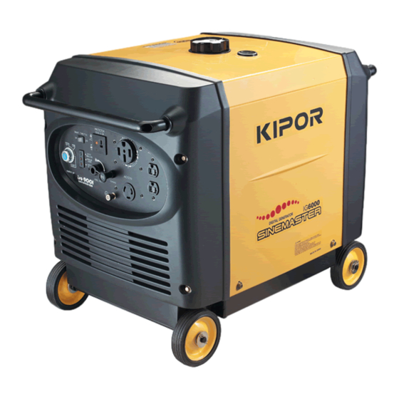
Kipor IG6000 Service Manual
Hide thumbs
Also See for IG6000:
- Service manual (52 pages) ,
- Operation manual (43 pages) ,
- Owner's manual (43 pages)

Related Manuals for Kipor IG6000


Summary of Contents for Kipor IG6000
- Page 1 IG6000 IG6000h Generator Service Manual The Coast Distribution System, June 1, 2007...
- Page 2 All information, illustrations, directions and specifications included in this publication are based on the latest product information available at the time of approval for printing. KIPOR POWER CO., LTD, reserves the right to make changes without incurring any obligation whatever. No part of this publication may be reproduced without written permission.
-
Page 3: Table Of Contents
TABLE OF CONTENTS 1. Specifications............................1 1.1 General Specifications........................1 1.2 Generator Specifications2......................2 1.3 Performance Curves........................3 1.4 Wiring Diagram..........................4 2. Service and Maintenance ……………………………………………………………………………………. 5 2.1 The Importance of Proper Service.……………………………………………………………………...5 2.2 Safety Precautions.……………………………………………………………………………………..5 2.3 Service Rules..........................6 2.4 Electrical Precautions..……………………………………………………………………………..7 2.5 Serial Number and Bar Code Location..................7 2.6 Alternator Service Standards.…………………………………………………………………………..8 2.7 Fastening Torques.………………………………………………………………………………………..8 2.8 Troubleshooting.…………………………………………………………………………………………..9... - Page 4 6.5 Ignition Module..........................24 6.6 Ignition Switch..........................25 6.7 Bridge Rectifier..........................25 6.8 Charge Regulator.........................26 6.9 Timing Relay..........................26 6.10 Ignition Control Module.......................27 6.11 Inverter Module...........................27 7. Frame, Housing, and Fuel Tank......................28 7.1 Disassembly and Reassembly......................28 7.2 IG600h Handle Assembly......................29 8. Ignition Coil, Trigger, Alternator......................30 8.1 Component Identification......................30 8.2 Ignition Coil and Trigger........................31 8.2.1 Disassembly and Reassembly...................31...
-
Page 5: Specifications
1.SPECIFICATIONS AND DIAGRAMS 1.1 General Specifications Dimensions and weights Model IG6000 IG6000H Overall length- in. (mm) 31.6 (802) 48.6 (1235) Overall width- in. (mm) 19.5 (498) 25.6 (650) Overall height- in. (mm) 24.6 (624) 30.3 (770) Dry weight- lbs. (Kg) -
Page 6: Generator Specifications2
1.2 Generator Specifications Model IG6000 6.0 KVA Maximum output(AC) Rated output (AC) 5.5 KVA Rated frequency (HZ) 120/240 Rated voltage(AC) Maximum current (amp) 25/50 23.9/45.8 Rated current(amp)★ Rated voltage(DC) Rated current(DC) Power factor Momentary Max.10% Voltage variation Average Max.1.5% rate Average time Max. -
Page 7: Performance Curves
1.3 PERFORMANCE CURVES The curves show performance of the generator under average conditions. Performance may vary depending upon ambient temperature, altitude and humidity. ●AC External characteristic curves ● DC External characteristic curves... -
Page 8: Wiring Diagram
1.4 Wiring Diagram... -
Page 9: Service And Maintenance
2. SERVICE AND MAINTENANCE 2.1 The importance of proper servicing Proper servicing is essential to the safety of the operator and the reliability of the generator. Any error or oversight made by the technician while servicing can easily result in faulty operation and/or damage to the equipment or injury to the operator. -
Page 10: Service Rules
2.3 Service Rules Use genuine KIPOR or KIPOR recommended parts and lubricants or their equivalents. Parts that do not meet Kipor’s design specifications may damage the engine and void the warranty. Use special tools designed for the product when specified. -
Page 11: Serial Number And Bar Code Location
Route the wire harnesses properly so that they do not contact sharp edges and corners and the end of the bolts and screws on the body. If a wire harness must contact the end of the bolts or screws or sharp edges and corners, protect the contact part of the harness with a loom or by winding with electrical insulating tape. -
Page 12: Alternator Service Standards
2.6 Alternator Maintenance Standards Standard(Ω) Service Part Item Type limit 120V/240V Orange- 0.22~0.24 Yellow/Green Ignition winding l Resistance Gray-orange 0.15~0.17 External charging Resistance Blue-blue 0.03~0.04 winding Built-in charging Resistance Purple-Purple 0.12~0.16 winding White-white Sub winding Resistance 0.08~0.12 (green-green) Black-black Main winding Resistance 0.45~0.60 0.09~0.10... -
Page 13: Troubleshooting
This section gives very general information regarding symptoms and possible causes. Refer to subsequent sections regarding testing and removal and replacement of specific components and systems. Engine overhaul is addressed in the IG6000 Engine shop manual. 2.8.1 General symptoms and possible causes... -
Page 14: Ignition System
→no spark Attach the spark plug on plug cap, ground Perform the ignition system troubleshooting the electrode on the cylinder head.; start or weak the engine and check the spark conditions spark ↓normal Install a compression gauge in the spark 1. -
Page 15: Low Oil Level Alarm
2.8.4 Engine oil level is low, but engine does not stop. Drain out all engine oil, disconnect the Replace the oil level alarm switch →not low oil alarm wire and check if the outlet conductive terminal is connected to ground ↓conductive Connect the alarm wire, loosen ignition Repair wiring harness... -
Page 16: Engine Stops After Starting
2.8.6 Engine stops after starting Check the engine oil level and check if Add oil and restart the engine →oil level oil level alarm activates when rotation alarm stops ↓sufficient oil →no fuel Check the fuel in fuel tank Add fuel and restart the engine ↓sufficient fuel Check for operation of fuel switch and Clean the fuel switch and filter... -
Page 17: Low Ac Output
output” ↓normal →abnormal Replace the stepping motor Check the stepping motor ↓normal →abnormal Replace the smart throttle switch Check the smart throttle switch ↓normal Check “Smart” switch wire →abnormal Repair or replace the wire harness ↓normal Replace the inverter unit 2.8.8 Low AC output →on Is the overload indicator light ON? -
Page 18: Electric Starter
2.8.10 Electric Starter →abnormal Charge or replace the battery Check the battery voltage ↓normal →abnormal Replace the ignition switch Check ignition switch ↓normal →abnormal Replace ignition relay Check the ignition relay ↓normal →abnormal Replace the starting motor Check the starting motor ↓normal Check and repair or replace main wire harness... -
Page 19: Inspection And Adjustment
3. INSPECTION AND ADJUSTMENT 3.1 MAINTENANCE SCHEDULE Regular service period(1) Each use Each Every 3 Every 6 Every year Item perform at every indicated month or months months or or every month or operating hour interval, every 10 or every every 100 300 hours whichever comes first... - Page 20 (3)Pour the specified amount of fresh engine oil through the oil filler port.(Engine oil capacity : 1.2 qt (1.1L) ※ Recommended engine oil: Use a high-detergent, premium quality 4-stroke engine oil, certified to meet or exceed U.S. automobile manufacturer’s requirements for API Service Classification SG, SF. Select the appropriate viscosity for the average temperature in your area.
-
Page 21: Low Oil Level Switch
3.3 Low Oil alarm inspection Disconnect the orange oil alarm wire when the engine stops and ground the terminal specified in the diagram and confirm that the alarm light is on and the engine stops or won’t restart. Outlet terminal of ignition module Outlet terminal of oil alarm Ground through engine cover 3.4 Air Cleaner... -
Page 22: Spark Plug
(4)Install the air cleaner element in the air cleaner case. Caution Do not operation the engine without an air filter element or with a damaged air filter. Rapid engine wear will result 3.5 Spark plug inspection and adjustment: (1)Remove the spark plug cap and remove the spark plug with plug sleeve (2)Remove carbon on the electrodes of spark plug with a wiey brush and check sealing washer for damage. -
Page 23: Valve Clearance
3.6 Valve clearance adjustment Caution ● Valve clearance inspection and adjustment must be performed on a cold engine. (1)Remove spark plug, valve cover bolt, valve cover and valve cover gasket. Spark plug Valve cover gasket Valve cover (2)Insert a feeler gauge in the spark plug installation hole; Rotate the engine so the piston is at top dead center and both intake and exhaust valves are closed. -
Page 24: Fuel Switch/Fuel Filter
(4)If adjustment is necessary, proceed as follows: a. lock the rocker lever adjustment screw and loosen the nut. b. move the rocker lever adjustment screw until the correct clearance is acheived. c. tighten the nut on the rocker arm adjustment screw. d. -
Page 25: Air Cleaner/Muffler
4.AIR CLEANER AND MUFFLER 4.1 Air cleaner ● Disassemble and reassemble Bottom case of air filter Sealed gasket Filter fixed price Filter element Carburetor gasket Air filter cover Install: Make sure that gaskets have no damage or deformation. Check sealing surfaces on all four sides 4.2 Muffler ●... -
Page 26: Carburetor
5. Carburetor WARNING This carburetor is not to be rebuilt nor adjusted and no repair parts will be furnished. The only maintenance permitted other than cleaning is to replace the main jet for high altitude compensation. 5.1 Disassembly and reassembly NOTE: loosen the drain bolt at the bottom of the bowl and drain fuel from the carburetor before removal. -
Page 27: Stepping Motor/Fuel Shutoff Solenoid
● Disassembly and installation of stepping motor Stepping motor Stepping motor base Fork Fork spring disassembly: Hold tight to prevent spring from coming loose Fork spring Fuel control lever Fork 5.2 Stepping motor/ fuel shutoff solenoid 1)Measure the resistance of outlet terminals of stepping motor 1 and 3:50~55Ω... -
Page 28: Control Panel And Inverter Module
Control Panel and Inverter 6.1 Disassembly and reassembly Timing relay Control panel Ignition control module Module fixing plate 2 Inverter unit Charging regulator Module fixing plate1 6.2 AC Receptacle Check for evidence of burning or contact damage. Replace if either condition exists. 6.3 DC Receptacle Connect both terminals of the receptacle with a jumper wire and check if the receptacle is conductive with two meter leads inserted into the panel;... -
Page 29: Ignition Switch
Color of wire Circuit unit Stipulated resistance 0.8~1.3Ω Blue Primary coil of the ignition coil Orange Oil level switch No continuity under normal oil level 80~130Ω Yellow Coil of trigger head Yellow/Green ground Continuity 0.37~0.41Ω Green Power coil winding of module Continuity when “OFF”... -
Page 30: Charge Regulator
(1)Negative terminal (-) (2) AC terminal (~) (3) AC terminal (~) (4)Negative terminal (+) 6.8 Charging Regulator Loosen the positive battery cable when starting the engine and connect a DC current meter between the positive cable and positive terminal. The indicated current cannot exceed 1.5A. If there is no current present, replace the regulator DC charging 13~14V... -
Page 31: Ignition Control Module
6.10 Ignition Control Relay Start the engine, turn off the smart throttle and measure the voltage between green and yellow/green wires on the connection of the control module. Replace the ignition control module if the voltage exceeds stipulated voltage. Ignition voltage 27~32V (AC) Yellow Green... -
Page 32: Frame, Housing, And Fuel Tank
7. FRAME, HOUSING, AND FUEL TANK 7.1 Disassembly and reassembly... -
Page 33: Ig600H Handle Assembly
7.2 IG6000h handle assembly... -
Page 34: Ignition Coil, Trigger, Alternator
ALTERNATOR, IGNITION COIL, TRIGGER, STARTER MOTOR, FAN COVER 8.1 Component Identification... -
Page 35: Ignition Coil And Trigger
8.2 Ignition coil and trigger 8.2.1 Disassembly and reassembly 触发头 点火线圈 Trigger Ignition 点火线圈支架 Bracket for ignition coil coil 8.2.2 Inspection a. Ignition coil ● using an ohmmeter, measure the primary resistance of the coil. Primary resistance 0.8~1.3Ω value ● measure the secondary resistance of the coil. Secondary resistance 15~21KΩ... - Page 36 ● Trigger Measure the trigger resistance. Trigger head 80~130Ω resistance ● Trigger Air Gap Adjustment Adjust the clearance between the trigger head and rotor. Trigger head .020-.029 in. (0.50~0.75 mm) clearance Insert the feeler gauge between the bulge on the trigger head and the rotor to measure clearance. Loosen the two bolts on the bracket to obtain the proper.
-
Page 37: Alternator
8.3 Alternator 8.3.1 Disassembly and reassembly Flywheel nut M8x1.5 88.5~95.9 ft. lb ( lob.(120~130N.m) 8.3.2 Inspection ● Ignition coil 0.22~0.24Ω Orange-Yellow/green Resistance value 0.15~0.17Ω Gray-Orange ● External charging coil Measure the resistance between the two blue wires 0.03~0.04Ω Resistance value ●... - Page 38 ●Main winding Measure the resistance between two wires in black. 0.45~0.60Ω Resistance value __________________________________________________________________________________ NOTES:...
Need help?
Do you have a question about the IG6000 and is the answer not in the manual?
Questions and answers