
Related Manuals for Kipor Sinamaster I G2600


Summary of Contents for Kipor Sinamaster I G2600
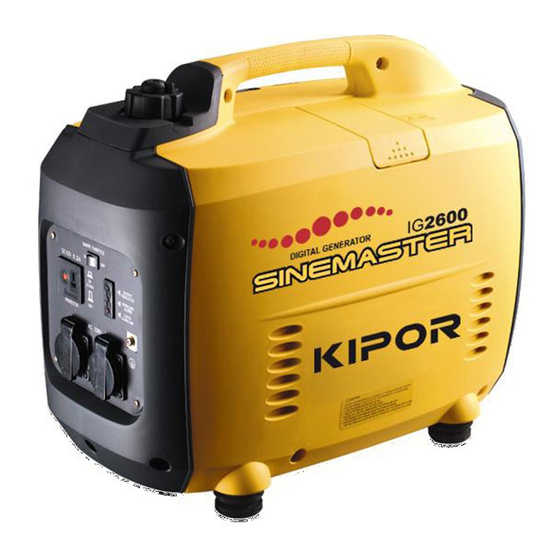
- Page 1 WUXI KIPOR POWER CO., LTD. S I N E M A S T E R DIGITAL INVERTER GENERATOR I G 2 6 0 0 I G 2 6 0 0 h...
- Page 3 PREFACE Thank you for purchasing our generators. This manual covers operation and maintenance of the IG2600, IG2600h generator. All information in this publication is based on the latest product information available at the time of approval for printing. We reserve the right to make changes at any time without notice and without incurring any obligation.
-
Page 4: Table Of Contents
CONTENTS 1. Safety Instructions 2. Safety Label Locations 3. Component Indentificaction 4. Pre-operation Check 5. Starting the Engine High altitude operation 6. Generator Use 7. Stopping the Engine 8. Maintenance 9. Transporting/Storage 10. Troubleshooting 11. Specifications 12. Electric diagram 13. Sketch Map 14. -
Page 5: Safety Instructions
14. APPENDIX 1. SAFETY INSTRUCTIONS Modified coefficient table Operate carefully and make sure users and others safety. WARNING of ambient condition power W A R N I N G The conditions of generator rated output: Our generators are designed to give safe anddependable Altitude: 0 m Ambient temperature: 25 Relative humidity: 30%... - Page 6 W A R N I N G 13. SKETCH MAP Gasoline is extremely flammable and explosive under certain conditions. Refuel in a well ventilated area with the engine stopped. Keep away from cigarette, smoke and sparks when re-fueling the generator. IG2600h Always refuel in a well-ventilated location.
-
Page 7: Safety Label Locations
12.ELECTRIC DIAGRAM 2. SAFETY LABEL LOCATIONS These lables warn you of potential hazards that can cause serious injury. Read the labels and safety notes and precautions described in this manual carefully. Parallel output If a label comes off or becomes hard to read, contact you dealer for a replacement. Choke lever Single phase receptacle... -
Page 8: Component Identification
3.COMPONENT IDENTIFICATION 11. SPECIFICATIONS Model IG2600/IG2600h Rated frequency (Hz) Chock Lever Rated voltage (V) Fuel Cap Lever Rated current (A) 10.0 19.2 Rated output (kVA) Fuel Filler Cap Max. output (kVA) Phase number Single phase DC output Control Panel Left Side DC output 12V-5A Maintenance... -
Page 9: Control Panel
Appliance does not operate: Control panel Is the output indicator light ON? Smart Throttle Switch Is the overload Take the generator to an Output Indicator Light Parallel receptacle indicator light ON? authorized dealer. Overload Indicator DC Circuit Light Protector Check the electrical appliance Take the generator to an Ground Terminal authorized dealer. - Page 10 Parallel receptacle 10.TROUBLESHOOTING The parallel cabinet can be connected with the parallel socket when the generator set needs a increasing of parallel output power. Smart throttle When the engine will not start: Engine speed is kept at idle automatically when the electrical appliance is Refill the fuel tank.
-
Page 11: Pre-Operation Check
a. Drain all gasoline from the fuel tank into an approved gasoline container. 4. PRE-OPERATION CHECK b. Turn the engine switch ON, and loosen the carburetor drain screw and drain the gasoline from the carburetor into a suitable container. c. With the drain screw loosened remove the spark plug cap, and pull the starter grip WARNING 3 to 4 times to drain the gasoline from the fuel pump. -
Page 12: Starting The Engine
WARNING 9.TRANSPORTING/STORAGE Running the engine with insufficient oil can cause serious engine damage. The Low Oil Alarm System will automatically stop the engine before the oil To prevent fuel spillage when transporting or during temporary storage, the generator level falls below the safe limit. However, to avoid the inconvenience of an should be secured upright in its normal operating position, with the engine swith OFF. - Page 13 1.Remove the four M5 screws, and remove the muffler protector. Fuel Filler Cap OPEN Seal strip of rear cover Upper Limit Mark Rear cover Gasoline containing alcohol 2.Remove the muffler, the spark arrester and the muffler gasket If you decide to use a generator containing alcohol (gasohol), be sure it's octane rating is at least as high as that recommended by us.
- Page 14 5.Visually inspect the spark plug. Discard it if the insulator is cracked or chipped. CAUTION Clean the spark plug with a wire brush if it is to be reused. 6.Measure the plug gap with a feeler gauge. Never run the engine without the air cleaner. Rapid en-gine wear will The gap should be 0.6-0.7 mm (0.024-0.028in).
-
Page 15: Starting The Engine
3.SPARK PLUG SERVICE 5.STARTING THE ENGINE RECOMMENTED SPARK PLUG: WR7DC To ensure proper engine operation, the spark plug must be properly gapped and NOTE free of deposits. Before starting the engine, disconnect the load from the DC terminals. 1.Remove the spark plug maintenance cover. When starting the generator after adding fuel for the first time or after long term storage, or after running out of fuel, turn the fuel valve lever to the ''ON'' position, then wait for 10 to 20 seconds before starting the engine. - Page 16 3.Move the choke lever to the START position. 2.AIR CLEANER SERVICE A dirty air cleaner will restrict air flow to the carburetor. T o prevent carburetor NOTE malfunction, service the air cleaner regularly. Service more frequently when operating the generator in extremely dusty areas. Do not use the choke when the engine is warm or the air temperature is high.
-
Page 17: High Altitude Operation
1.CHANGING OIL 5. Move the choke lever to the RUN position after the engine warms up. Drain the oil while the engine is still warm to assure rapid and complete draining. CAUTION Chock Lever M a k e s u r e t o t u r n t h e e n g i n e s w i t c h a n d t h e f u e l c a p lever OFF before draining. -
Page 18: Generator Use
6.GENERATOR USE 8.MAINTENANCE The purpose of the maintenance and adjustment schedule is to keep the generator WARNING in the best operating condition. To prevent electrical shock from faulty appliances, the generator should be WARNING grounded. Connect a length of heavy wire between the generator's ground terminal and an external ground source. - Page 19 3.Turn the cap lever fully counterclockwise to the "OFF" position NOTE The DC receptacle can be used while the AC power is in use. if you use both at the same time, be sure not to exceed the total power for AC and DC. Fuel Cap Lever Electrical equipment (including electrical lines and plugs connection) could not be defective.
-
Page 20: Stopping The Engine
Output and Overload Indicators 7.STOPPING THE ENGINE The output indicator light(green) will remain ON during normal operating conditions. If the generator is overloaded(in excess of 2.6kVA), or if there is a short in the To stop the engine in an emergency, turn the engine switch to the OFF position. connected appliance, the output indicator light(greer) will go OFF, the overload IN NORMAL USE: indicator light(red) will go ON and current to the connected appliance will be shut... - Page 21 1.Connect the ground terminal. Fuse Earth Mark DC Circuit Protector Low oil alarm system 2. Start each engine according to "STARTING THE ENGINE". The Low oil alarm system is designed to prevent engine damage caused by an When the output indicator light(green)does not light and the overload indicator insufficient amount of oil in the crankcase.
- Page 22 4.Switch on the equipment to be used. WARNING In case of overload operation or when trouble occurs for the equipment being used, the output indicator light(green) will go out, the overload indicator light(red) will light To prevent the possibility of creating a spark near the battery, connect charging cable first to the generator, then to the battery.
Need help?
Do you have a question about the Sinamaster I G2600 and is the answer not in the manual?
Questions and answers