Kipor SINEMASTER IG2000 Operation Manual
Digital generator
Hide thumbs
Also See for SINEMASTER IG2000:
- Shop manual (90 pages) ,
- Operation manual (54 pages) ,
- Manual (74 pages)
Table of Contents
Advertisement
Beside Jingyi Road
Third Stage Development Section of
Wangzhuang Industry Area, Wuxi High &
New Technology Industry Development Zone
Wuxi, Jiangsu Province, PRC
TEL: 0086-510-85200888
FAX: 0086-510-85200999
E-MAIL: kipor@kipor.com
Version 1, Printing date December 03, 2008. Coast CARB
MADE IN CHINA
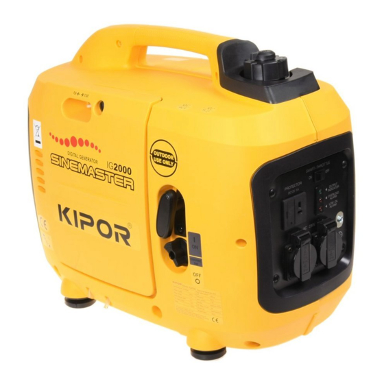
SINEMASTER
DIGITAL GENERATOR
IG2000
IG2000p
OPERATION MANUAL
Advertisement
Table of Contents

Related Manuals for Kipor SINEMASTER IG2000


Summary of Contents for Kipor SINEMASTER IG2000
- Page 1 Third Stage Development Section of Wangzhuang Industry Area, Wuxi High & New Technology Industry Development Zone Wuxi, Jiangsu Province, PRC TEL: 0086-510-85200888 FAX: 0086-510-85200999 E-MAIL: kipor@kipor.com Version 1, Printing date December 03, 2008. Coast CARB SINEMASTER MADE IN CHINA DIGITAL GENERATOR IG2000...
- Page 2 This page intentionally blank.
-
Page 3: Preface
PREFACE Thank you for purchasing our generators. This manual covers operation and maintenance of the Coast Distribution model IG2000 and IG2000p generators. All information in this publication is based on the latest product information available at the time of approval for printing. - Page 4 Gives helpful information. If a problem should arise, or if you have any questions about the generator, consult an authorized dealer. Our generators are designed to give safe and dependable service if operated according to instructions. Read and understand the Owner's Manual before operating the generator. Failure to do so could result in personal injury or equipment damage.
-
Page 5: Table Of Contents
CONTENTS PREFACE ........................1 1. SAFETY INSTRUCTIONS ..................4 2. SAFETY LABEL LOCATIONS ................6 3. COMPONENT IDENTIFICATION ................7 4. PRE-OPERATION CHECK ..................11 5. STARTING THE ENGINE ..................15 6. GENERATOR USE ....................17 7. STOPPING THE ENGINE ..................26 8. -
Page 6: Safety Instructions
1. SAFETY INSTRUCTIONS ■ This generator is designed to give safe and dependable service if operated according to instructions. Read and understand the Owner's Manual before operating the generator. Failure to do so could result in personal injury or equipment damage. ■... - Page 7 ■ Wipe up spilled gasoline immediately. ■ Always make a pre-operation inspection before you start the engine. You may prevent an accident or equipment damage. ■ Place the generator at least three feet or one meter away from buildings or other equipment during operation.
-
Page 8: Safety Label Locations
2. SAFETY LABEL LOCATIONS These labels warn you potential hazards that can cause serious injury. Read the labels and safety notes and precautions described in manual carefully. If a label comes off or becomes hard to read, contact your dealer for a replacement. CHOKE LEVER LOW OIL ALARM ENGINE SWITCH... -
Page 9: Component Identification
3. COMPONENT IDENTIFICATION FUEL CAP VENT LEVER CHOKE LEVER FUEL FILLER CAP CONTROL PANEL MAINTENANCE COVER STARTER GRIP ENGINE SWITCH SPARK PLUG MAINTENANCE COVER MUFFLER AIR EXHAUST AIR INTAKE... - Page 11 Control panel SMART-THROTTLE SWITCH OUTPUT INDICATOR LIGHT OVERLOAD INDICATOR LIGHT DC RECEPTACLE GROUND TERMINAL DC CIRCUIT PROTECTOR LOW OIL ALARM INDICATOR LIGHT AC RECEPTACLE...
- Page 12 Serial number and bar code identification and location The generator serial number identifies your particular unit and is important when ordering parts and accessories. The bar code is used by your dealer and Coast Distribution for warranty administration. The serial number can be found stamped on the engine block above oil dipstick.
-
Page 13: Pre-Operation Check
4. PRE-OPERATION CHECK ■ Be sure to check the generator on a level surface with the engine stopped. 1. Check the engine oil level. ■ Using non detergent oil or 2 cycle engine oil could shorten the engine's service life. Use a high-detergent, premium quality 4-stroke engine oil, certified to meet or exceed U.S. - Page 14 NOTE: The Low Oil Alarm System will automatically stop the engine before the oil level falls below the safe limit. However, to avoid the inconvenience of an unexpected shutdown, it is still advisable to visually inspect the oil level regularly. You must screw down the dipstick completely to measure the oil level.
- Page 15 Fuel tank capacity: 0.9 gal (3.4 liters) Gasoline containing alternate fuels If you decide to use a gasoline containing ethanol, be sure its octane rating is lower than the specification. Do not use a blend that contains more than 15% ethanol. Do not use gasoline containing methanol.
- Page 16 3. Check the air cleaner Check the air cleaner element to be sure it is clean and in good condition. Loosen the cover screw and remove the left side maintenance cover. Press the latch tab on the top of the air cleaner body, remove the air cleaner cover, check the element.
-
Page 17: Starting The Engine
5. STARTING THE ENGINE Before starting the engine, disconnect any load from the AC receptacle. 1. Turn the engine switch to the ON position. ENGINE SWITCH 2. Move the choke lever to the START position. NOTE: Do not use the choke when the engine is warm or the ambient air temperature is high. START CHOKE LEVER START... - Page 18 ■ Do not allow the starter grip to snap back. Return it slowly by hand. STARTER GRIP 4. Move the choke lever to the RUN position after the engine warms up. CHOKE LEVER ■ If the engine stops and will not restart, check the engine oil level before further troubleshooting.
-
Page 19: Generator Use
6. GENERATOR USE Be sure to ground the generator when loads are connected. ■ To prevent electrical shock from faulty appliances, the generator should be grounded. Connect a length of heavy cable between the generator's ground terminal and an external ground source. - Page 20 ■ The total wattage of all appliances connected must be considered. ■ Do not exceed the current limit specified for any one receptacle. ■ Do not connect the generator to a household circuit. This could cause the damage to the generator or to electrical appliances in the house.
- Page 21 AC application 1. Start the engine and make sure only the output indicator light (green) comes on. 2. Confirm that the appliance to be used is switched off, and plug in the appliance. OVERLOAD INDICATOR OUTPUT INDICATOR LIGHT LIGHT PLUG ■...
- Page 22 Output and Overload Indicators The output indicator light (green) will remain on during normal operating conditions. If the generator is overloaded (in excess of 2.0 KW), or if there is a short in the connected appliance, the output indicator light (green) will go out, the overload indicator light (red) will illuminate and current to the connected appliance will be shut off.
- Page 23 DC application The DC receptacle may be used for charging 12 volt automotive-type batteries only, the no load voltage is 15V-30V. ■ In DC operation, turn the Smart-throttle switch to the OFF position. 1. Connect the charging cables to the DC receptacle of the generator and then to the battery terminals.
- Page 24 ■ The battery gives off explosive gases; keep spark, flames and cigarettes away. Provide adequate ventilation when charging. ■ The battery contains sulfuric acid (electrolyte). Contact with skin or eyes may cause severe burns. Wear protective clothing and a face shield. -If electrolyte gets on your skin, flush with water.
- Page 25 Low oil alarm system The low oil alarm system is designed to prevent engine damage caused by an insufficient amount of oil in the crankcase. Before the oil level in the crankcase falls below a safe limit, the low oil alarm system will automatically shut down the engine (the engine switch will remain in the ON position).
- Page 26 Smart Throttle System When the smart throttle switch is placed in the on position, engine speed is kept at idle automatically when the electrical load is disconnected and returns to the proper speed to match the power of the electrical load when the load is reconnected. This position is recommended to minimize fuel consumption while in operation.
- Page 27 High altitude operation At higher altitudes, the standard carburetor air-fuel mixture will be excessively rich. Performance will decrease, and fuel consumption will increase. Power output will decrease 3.5% for each 1000 feet (305 m) above sea level. High altitude performance can be improved by installing a smaller diameter main fuel jet in the carburetor.
-
Page 28: Stopping The Engine
7. STOPPING THE ENGINE To stop the engine in an emergency, turn the engine switch to the OFF position. IN NORMAL USE: 1. Switch off the connected equipment and pull the inserted plug out. PLUG 2. Turn the engine switch to the OFF position ENGINE SWITCH... -
Page 29: Parallel Generator Operation
8. PARALLEL GENERATOR OPERATION Parallel operation features: Two separate IG2000p models can run in parallel to increase the total output to a max load of 4000W. Parallel operation is not possible with either one or both generators not being an IG2000p. - Page 30 Fig. 1 a. L5-30 Twistlock b. RV style receptacle receptacle Fig.2 2. First connect two “PARALLEL I/O ①” terminals on each control panels with the special parallel connection cable and tighten the plug (Fig. 3). 3. Second, securely plug the connector plugs④ of the parallel cable③ into the connector receptacles marked PARALLEL OUTPUT⑤...
- Page 31 Fig. 5 Note: The required output of the electrical appliance cannot exceed the rated output of parallel generators. Shutting off the generators: 1. Turn off the power of electrical appliance, pull out the receptacle plug. 2. Turn off the two generators. 3.
- Page 32 · Don't disconnect the PARALLEL I/O special connection cable and parallel output cable during parallel operation; connect the PARALLEL I/O special connection cable before starting the engine then connect the parallel output cable. You can disconnect the PARALLEL I/O special connection cable and parallel output cable only after stopping the generator.
-
Page 33: Maintenance
Carbon monoxide is a poisonous gas. The emission of fuel vapors is a source of pollution as well. The Kipor generator engine utilizes a precise air-fuel ratio and emission control system to reduce the emissions of carbon monoxide, NO , hydrocarbons, and evaporative fuel emissions. - Page 34 You can trust the replacement parts supplied by Kipor have been manufactured to the same production standard as the original parts. The use of replacement parts or accessories which are not designed by Kipor may affect the engine emission performance.
- Page 35 Description Emission Duration Period Short-term 50 hrs(0-80CC), 125 hrs(>80CC) 125 hrs (0-80CC), 250 hrs(>80CC) Medium-term 300 hrs (0-80CC) , 500 hrs (>80CC) , 1000 hrs (≥225CC) Long-term The air quality index label is designed to be permanently affixed to the generator and removal should not be attempted.
- Page 36 1. Loosen the cover screw and remove the left side maintenance cover. 2. Remove the oil filler cap. 3. Drain dirty oil into a container thoroughly. 4. Refill with the recommended oil, and check the oil level. 5. Reinstall the left side maintenance cover and tighten the cover screw securely. Engine oil capacity: 0.42 qt.
- Page 37 ■Never run the generator without the air cleaner, otherwise rapid engine wear may result. 1. Loosen the cover screw and remove the left side maintenance cover. 2. Remove the air cleaner cover and remove the fine and coarse elements. 3. Wash the elements in a non-flammable or high flash point solvent and dry it thoroughly. 4.
- Page 38 3. SPARK PLUG MAINTENANCE RECOMMENTED SPARK PLUG: UR5 To ensure proper engine operation, the spark plug must be properly gapped and free of deposits. 1. Remove the spark plug maintenance cover. Spark plug maintenance cover 2. Remove the spark plug cap. 3.
- Page 39 5. Visually inspect the spark plug. Discard it if the insulator is cracked or chipped. Clean the spark plug with a wire brush if it is to be reused. 6. Measure the plug gap with a feeler gauge. The gap should be 0.024-0.028in (0.6-0.7mm). Correct as necessary by carefully bending the side electrode.
-
Page 40: Transporting/Storage
10. TRANSPORTING and STORAGE To prevent fuel spillage when transporting or during temporary storage, the generator should be secured upright in its normal operating position with the engine switch OFF. When transporting the generator: ■ Do not overfill the tank (there should be no fuel in the filler neck). ■... - Page 41 Exercising the Generator It is essential that the generator be exercised on a regular basis. This will prevent the accumulation of varnish or sludge in the fuel system and also remove moisture from the generator windings. Additionally the engine seals and moving components are lubricated. Exercise the generator by running it with at least a 1/2 load (1000W) for 60 minutes per month.
-
Page 42: Troubleshooting
11. TROUBLESHOOTING Engine will not start: Is there fuel in the tank? Refuel the fuel tank Is the engine switch on? Turn the engine switch on. Is the enough oil in the engine? Add the recommended oil. Still no Is there a spark from Replace the spark plug. - Page 43 Appliance does not operate: Is the output indicator light ON? Take the generator to an Is the overload in- authorized dealer. dicator light ON? Check the electrical appli- NO DEFECTS Take the generator to an ance or equipment for any authorized dealer.
-
Page 44: Specifications
12. SPECIFICATIONS Generator Model IG2000 /IG2000p Rated frequency (Hz) Rated voltage (V) Rated current (A) 13.3 Max current (A) 16.6 Rated output (W) 1600 Max output (W) 2000 DC Output 12 V, 5.0 A Phase Single Engine Model KG158 Type... -
Page 45: Wiring Diagrams
13. WIRING DIAGRAMS IG2000... - Page 46 IG2000p...
-
Page 47: Warranty
Starting batteries included with a generator are warranted for a period or one year. Kipor must warrant the emission control system for a period of two years provided there has been no improper maintenance, abuse or neglect. See the emission control warranty in the section immediately following the limited warranty description. -
Page 48: Emission Control System Warranty
Emission Control System Warranty Your Kipor generator engine complies with U.S. Environmental Protection Agency, Environment of Canada, and the state of California (if the model is certified by CARB). The following systems and/or parts are covered by this warranty. Failures or improper operation of the following systems and components will be diagnosed and repaired with no charge for labor or parts. -
Page 49: Appendix A- Mobile Light Kit Installation
(7) Screw M5×16 1PCS Assembly: (1) Remove the screw from the IG2000 Portable Digital Generator and the screws from the side of the control plate; (2) Install the mounting plates on the generator using the M5×45 and M5×16 screws. DO NOT TIGHTEN SCREWS. -
Page 50: Appendix B- Emission Control System
3. A catalyst is built into the muffler to further treat the engine exhaust. 4. A secondary air injection valve adds combustion air to ignite unburned fuel in the exhaust. Contact your authorized Kipor service center to obtain the correct replacement parts and service on this system.
Need help?
Do you have a question about the SINEMASTER IG2000 and is the answer not in the manual?
Questions and answers