Kipor SINEMASTER IG6000 Owner's Manual
Digital generator
Hide thumbs
Also See for SINEMASTER IG6000:
- Service manual (52 pages) ,
- Operation manual (43 pages) ,
- Operation manual (18 pages)
Table of Contents
Advertisement
Beside Jingyi Road
Third Stage Development Section of
Wangzhuang Industry Area, Wuxi High &
New Technology Industry Development Zone
Wuxi, Jiangsu Province, PRC
TEL: 0086-510-85200888
FAX: 0086-510-85200999
E-MAIL: kipor@kipor.com
Version 2, Printing date December 29 2008. Coast CARB
MADE IN CHINA
SINEMASTER
DIGITAL GENERATOR
IG6000
IG6000h
OWNER'S MANUAL
Advertisement
Table of Contents

Subscribe to Our Youtube Channel
Related Manuals for Kipor SINEMASTER IG6000


Summary of Contents for Kipor SINEMASTER IG6000
- Page 1 Third Stage Development Section of Wangzhuang Industry Area, Wuxi High & New Technology Industry Development Zone Wuxi, Jiangsu Province, PRC TEL: 0086-510-85200888 FAX: 0086-510-85200999 E-MAIL: kipor@kipor.com SINEMASTER DIGITAL GENERATOR IG6000 Version 2, Printing date December 29 2008. Coast CARB IG6000h MADE IN CHINA OWNER’S MANUAL...
- Page 3 PREFACE Thank you for purchasing a KIPOR generator from the Coast Distribution System. This manual covers operation and maintenance of the California Air Resources Board (CARB) approved IG6000 and IG6000h generator. All information in this publication is based on the latest product information available at the time of approval for printing.
- Page 4 If a problem should arise, or if you have any questions about the generator, consult an authorized KIPOR dealer. KIPOR generator is designed to give safe and dependable service if operated according to instructions. Read and understand the Owner's Manual before operating the generator. Failure to do so could result in...
-
Page 5: Table Of Contents
CONTENTS 1. SAFETY INSTRUCTIONS ················································································· 1 2. COMPONENT LOCATIONS ·············································································· 3 2.1 Outside View ····························································································· 3 2.2 Control Panel ····························································································· 4 2.3 Serial Number and Bar Code Location ···························································· 4 3. PRE-OPERATION CHECK ················································································ 5 3.1 Engine Oil ································································································· 5 3.1 Fuel ·········································································································... - Page 6 11. WIRING DIAGRAM ······················································································· 29 12. WHEEL KIT INSTALLATION ··········································································· 30 12.1 IG6000 ··································································································· 30 12.2 IG6000h ································································································· 31 13. WARRANTY ································································································ 32 13.1 Limited Warranty- Kipor Power Products ····················································· 32 13.2 Emission Control Warranty ······································································· 33 14. EMISSION CONTROL SYSTEM ······································································ 34...
-
Page 7: Safety Instructions
1. SAFETY INSTRUCTIONS ■The generators are designed to give safe and dependable service if operated according to the instructions. Read and understand the Owner's Manual before operating the generator. Failure to do so could result in personal injury or equipment damage. !WARNING ■Exhaust gas contains poisonous carbon monoxide a colorless, odorless, poisonous gas. -
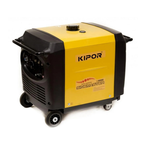
Page 8: Component Locations
2. COMPONENT LOCATIONS 2.1 Outside view 火花塞 Spark plug Service door 维修门 控制面板 Control panel Air intake 进气口 放 油螺塞 Oil drain 机油尺 Dipstick screw 碳罐 Carbon canister 空 滤器 Air filter Fuel level indicator 油位指示器 Fuel filler cap 油箱盖 空气指数信息铭牌... -
Page 9: Control Panel
2.2 Control panel Choke knob AC Receptacle DC Receptacle Smart switch Overload protector Start switch Ground terminal Fuel switch Annunciator Panel... -
Page 10: Serial Number And Bar Code Location
2.3 Serial Number and Bar Code Location The engine serial number is stamped on the engine block to the left of the oil drain plug. In most cases the battery will have to be removed to view it clearly. Refer to this number when ordering parts or making technical inquiries. -
Page 11: Pre-Operation Check
3. PRE-OPERATION CHECK Be sure to check the generator on a level surface with the engine stopped. 3.1 Engine Oil WARNING ■ Using non detergent or 2-stroke engine oil could shorten the engine's service life. ■ Use a high-detergent, premium quality four cycle engine oil, certified to meet or exceed U.S. Automobile manufacturer's requirements for API Service Classification SG/SF. -
Page 12: Fuel
CAUTION ■Running the engine with insufficient oil can cause serious engine damage. ■The oil Alert System will automatically stop the engine before the oil level falls below the safe limit. However, to avoid the inconvenience of an unexpected shutdown, it is still advisable to visually inspect the oil level before each use. -
Page 13: Air Cleaner
GASOLINES CONTAINING ALTERNATE FUELS If you decide to use a gasoline containing ethanol or methanol, be sure its octane rating is no lower than the specification. Do not use a blend that contains more than 15% ethanol. An ethanol blend will produce lower power and higher fuel consumption. -
Page 14: Starting The Engine
4. STARTING THE GENERATOR CAUTION ■When starting the generator after adding fuel for the first time, after long-term storage, or after running out of fuel, turn the fuel valve lever to the "ON" posit-ion and then wait for 10 to 20 seconds before starting the engine. - Page 15 C. Insert the engine key, and turn the engine switch to on position. START Engine switch On Position D. Turn the engine switch to the START until the engine has started. Do not engage the starter for more than 10 seconds. START Engine switch Starting Position...
-
Page 16: High Altitude Operation
4.2High altitude operation At high altitude, the standard carburetor air-fuel mixture will be excessively rich. Performance will decrease, and fuel consumption will increase. High altitude performance can be improved by installing a smaller diameter main jet in the carburetor. If you continuously operate the generator at altitudes higher than 5000 feet or 1500 meters above sea level, have your authorized dealer install the high altitude main jet kit. -
Page 17: Generator Use
5. GENERATOR USE 5.1 Warnings and Cautions WARNING ■To prevent electrical shock from faulty appliances, the generator should be grounded. The ground terminal is connected to the generator frame and the ground terminal of each receptacle. Connect a length of heavy gauge wire between the generator's ground terminal and an external ground source if required by local code. -
Page 18: Ac Power Applications
5.2 AC applications 1. Start the engine and make sure the output indicator light (green) comes on. 2. Confirm that the appliance to be used is switched off, and plug in the appliance. Applying Loads CAUTION ■Substantial overloading that continuously lights the overload indicator light (red) may damage the generator. -
Page 19: Ac Load Management
5.4 AC Load Management The generator has the following receptacles: 1- 240V/50A 14-50R 1- 120V/20A 5-20R duplex 1- 120V/30A L5-30R twistlock Maximum load from the various receptacles is as follows: - 240V AC at 25 amps is available from the 50A receptacle. Connecting this receptacle to a 50A service receptacle will allow 25 amps @ 120 volts to two separate legs. -
Page 20: Smart Throttle
5.5 Smart Throttle Engine speed is kept at idle automatically when the electrical load is disconnected and it returns to the proper speed when the load is reconnected. This position is recommended to minimize fuel consumption while in operation Smart throttle Smart Throttle Switch NOTE ■When high electrical load appliances are connected simultaneously. -
Page 21: Dc Power Operation
5.7 DC application The DC receptacle may be used for charging 12 volt automotive-type batteries only. It is not designed to operate DC motors. Output voltage is 15-30V. DC output will vary according to the position of the Smart throttle switch. 1. -
Page 22: Low Oil Alarm System
■ Keep out of reach of children. The DC output is to be used to charge batteries only. Serious damage to the stator windings can occur if connected to a DC motor or transformer. 2. Start the generator. ■ The DC receptacle may be used while the AC power is in use. ■... -
Page 23: Stopping The Engine
6. STOPPING THE GENERATOR 6.1 Normal Shutdown In normal use: 1. Switch off the connected equipment and pull the plug from the receptacle. 2. Turn off the engine switch. 3. Turn the fuel valve lever to the OFF position. 6.2 Emergency Shutdown To stop the generator in an emergency, turn the engine switch to the OFF position. -
Page 24: Maintenance
Carbon monoxide is a poisonous gas. The emission of fuel vapors is a source of pollution as well. The Kipor generator engine utilizes a precise air-fuel ratio and emission control system to reduce the emissions of carbon monoxide, NO , hydrocarbons, and evaporative fuel emissions. - Page 25 You can trust the replacement parts supplied by Kipor have been manufactured to the same production standard as the original parts. The use of replacement parts or accessories which are not designed by Kipor may affect the engine emission performance.
-
Page 26: Maintenance Schedule
7.2Maintenance Schedule REGULAR SERVICE PERIOD (1) FIRST EVERY 3 EVERY 6 EVERY Perform at every indicated month or EACH MONTH MONTHS MONTHS MONTHS operating hour interval, whichever occurs first 20HRS 50HRS 100HRS 300HRS ITEM Engine oil Check ○ Change ○ ○... -
Page 27: Changing Oil
7.3 Changing oil Drain the oil while the engine is still warm to assure rapid and complete draining. See Fig.15. Upper limit Lower limit Oil drain bolt Dipstick 1. Open the service door. 2. Take out the oil outlet plug. 3. -
Page 28: Spark Plug Service
1. Open the left side maintenance door. 2. Unsnap the clips and remove the air cleaner cover. 3. Remove the air cleaner element and examine for dirt or damage. Replace it with a new one if necessary. Do not attempt to clean the paper element. 4. -
Page 29: Spark Arrestor Maintenance
as necessary by carefully bending the side electrode. Plug gap Fig. 17 Spark Plug Gap CAUTION ■The spark plug must be securely tightened. An improperly tightened plug can become very hot and possibly damage the generator. ■Never use a spark plug with an improper heat range. 7. - Page 30 6. Reinstall the rear cover. Secondary air injection valve 二次补气阀 火星捕捉器 Spark arrester Rear cover 后面罩 -24-...
-
Page 31: Transporting/Storage
8. TRANSPORTING/STORAGE 8.1 Transporting. When transporting the generator, turn the fuel valve lever OFF and keep the generator level to prevent fuel spillage. Fuel vapor or spilled fuel may ignite. Do not transport the generator in a vehicle with fuel in the tank. -
Page 32: Troubleshooting
Is the enough oil in the engine? Take the generator to Still no spark Replace the Is there a spark from an authorized KIPOR spark plug. the spark plug? dealer. To check: 1) Remove the spark plug cap and clean any Be sure there is no spilled ■... -
Page 33: No Ac Power
ON? authorized dealer. Check the electrical appliance or Take the generator to an equipment for any defects. authorized KIPOR dealer. ■ Replace the electrical appliance or equipment ■ Take the electrical appli- ance or equipment to an electrical shop for repair 9.3 No electricity at the DC receptacle:... -
Page 34: Specifications
10. SPECIFICATIONS Generator Model IG6000/IG6000h Rated frequency (Hz) Rated voltage (V) 120/240 Rated current (A) 45.8/22.9 Rated output (Watts) 5500 Max current (A) Max output (Watts) 6000 DC voltage 12V@5.0A Phase Single Engine Model KG390GTi Type Single cylinder, 4 stroke, vertical, air-cooled, OHV, gasoline engine Displacement (Bore ×... -
Page 35: Wiring Diagram
11. WIRING DIAGRAM -29-... -
Page 36: Wheel Kit Installation
12. WHEEL INSTALLATION 12.1 IG6000 1. Washer (4) 2. Front Wheel (2) 3. Wheel Clip (2) 4. Locking Swivel Wheel (2) 5. Bolt M6X16 (8) To install the front wheels, install a washer on the axle, then the wheel, another washer and secure with a wheel clip. -
Page 37: Ig6000H
IG6000H 1. IG6000H Chassis- installed 5. 10” Wheel 2. Support Bracket- (4) 6. Wheel Washer (4) 3. Front Stabilizer (2) 7. Wheel Clip 4. Axle Assembly Assembly: 1. Install the four support brackets and secure with bolts. 2. Attach the front stabilizers to the chassis (below the handles) 3. -
Page 38: Warranty
Units used in rental fleets or as demonstration models will be considered commercial usage. Starting batteries included with a generator are warranted for a period or one year. Kipor must warrant the emission control system for a period of two years provided there has been no improper maintenance, abuse or neglect. -
Page 39: Emission Control Warranty
13.2 Emission Control System Warranty Your Kipor generator engine complies with U.S. Environmental Protection Agency, Environment of Canada, and the state of California.. The following systems and/or parts are covered by this warranty. Failures or improper operation of the following systems and components will be diagnosed and repaired with no charge for labor or parts. -
Page 40: Emission Control System
3. A catalyst is built into the muffler to further treat the engine exhaust. 4. A secondary air injection valve adds combustion air to ignite unburned fuel in the exhaust. Contact your authorized Kipor service center to obtain the correct replacement parts and service on this system. - Page 41 Exhaust system 二次补气阀组件 Secondary air injection valve Bolt 螺栓 Spark arrestor 防火帽组件 Muffler assembly 消声器本体总成 Muffler gasket 垫片A Exhaust pipe 排气管 -35-...
- Page 42 Carbon Canister Installation Frame Strap 碳 罐 固 定 皮 带 大 气 弯 管 Curved hose 碳 罐 Canister 油 箱 通 气 管 Vent hose 碳 罐 负 压 管 -36-...
-
Page 43: Fuel System
Fuel System 油箱盖总成 Fuel tank cover 油箱盖 Sleeve Bushing 油箱盖内螺纹套 油箱盖内棘爪 开口销 油箱盖内称套 Washer Strainer 垫圈 加油口过滤网 油箱盖内垫片 Gasket Hook 防掉倒钩 Certificate No. 材 料和证书编号 X6800BM 油箱 Gas tank X6800BM Q-08-006 Q-08-006 证书编号 Certificate No. C-U-07-016 C-U-07-016 Mounting strap 碳罐固定皮带 Fuel switch 油开关组件...
Need help?
Do you have a question about the SINEMASTER IG6000 and is the answer not in the manual?
Questions and answers