Kipor IG3000 Owner's Manual
Sinemaster digital generator
Hide thumbs
Also See for IG3000:
- Operation manuals (42 pages) ,
- Operation manual (41 pages) ,
- Operation manual (18 pages)
Table of Contents
Advertisement
Beside Jingyi Road
Third Stage Development Section of
Wangzhuang Industry Area, Wuxi High &
New Technology Industry Development Zone
Wuxi, Jiangsu Province, PRC
TEL: 0086-510-85200888
FAX: 0086-510-85200999
E-MAIL: kipor@kipor.com
Version 1, Printing date Dec. 15, 2008 Coast (CARB)
MADE IN CHINA
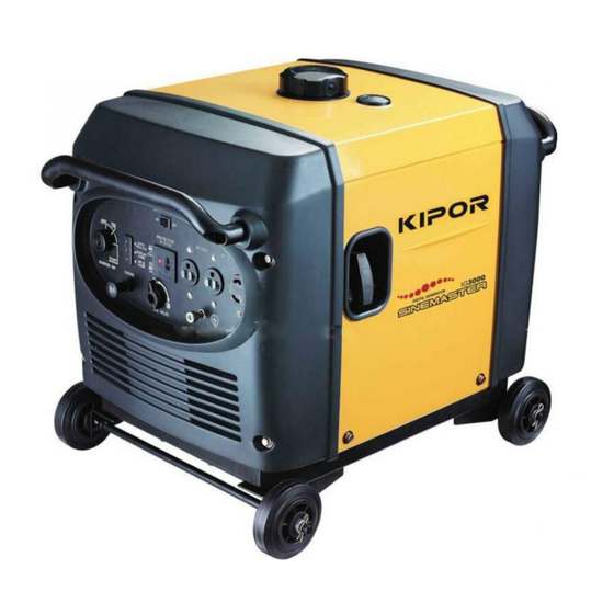
SINEMASTER
DIGITAL GENERATOR
IG3000
OWNER'S MANUAL
Advertisement
Table of Contents

Subscribe to Our Youtube Channel
Related Manuals for Kipor IG3000


Summary of Contents for Kipor IG3000
- Page 1 Third Stage Development Section of Wangzhuang Industry Area, Wuxi High & New Technology Industry Development Zone Wuxi, Jiangsu Province, PRC TEL: 0086-510-85200888 FAX: 0086-510-85200999 E-MAIL: kipor@kipor.com SINEMASTER DIGITAL GENERATOR IG3000 OWNER’S MANUAL Version 1, Printing date Dec. 15, 2008 Coast (CARB)
- Page 3 PREFACE Thank you for purchasing a Kipor Generator from the Coast Distribution System. This manual covers the operation and preventive maintenance of the IG3000 generator with California Air Resources Board (CARB) certification. All information in this publication is based on the latest product information available at the time of printing.
- Page 4 The portable generator is not meant to be used as a permanent back-up power system for the home. A permanently installed stationary generator is designed to be safely used for this specific purpose. Indicates a strong possibility of severe personal injury or death if instructions are not followed.
-
Page 5: Table Of Contents
CONTENTS 1. SAFETY INSTRUCTIONS ················································································· 1 2. COMPONENT LOCATIONS ·············································································· 3 2.1 Outside View ····························································································· 3 2.2 Control Panel ····························································································· 4 2.3 Serial Number and Bar Code Location ···························································· 4 3. PRE-OPERATION CHECK ················································································ 5 3.1 Engine Oil ································································································· 5 3.1 Fuel ·········································································································... - Page 6 9. TROUBLESHOOTING ····················································································· 25 10. SPECIFICATIONS ························································································ 27 11. WIRING DIAGRAM ······················································································· 28 12. WHEEL KIT INSTALLATION ··········································································· 29 13. WARRANTY ································································································ 30 13.1 Limited Warranty- Kipor Power Products ····················································· 30 13.2 Emission Control Warranty ······································································· 31 14. EMISSION CONTROL SYSTEM ······································································ 32...
-
Page 7: Safety Instructions
1. SAFETY INSTRUCTIONS ■Our generators are designed to give safe and dependable service if operated according to these instructions. Read and understand the owner's manual before operating the generator. Failure to do so could result in personal injury or equipment damage. ■Exhaust gas contains poisonous carbon monoxide. - Page 8 To ensure safe operation: ■ Gasoline is extremely flammable and explosive under certain conditions. Refuel in a well ventilated area with the engine stopped. ■Keep away from smoking materials, sparks and other sources of combustion when refueling the generator. Always refuel in a well-ventilated location.
-
Page 9: Component Locations
2. COMPONENT LOCATIONS 2.1 Outside view 碳罐 Carbon Canister 火花塞 Spark plug 机油尺 Oil dipstick 控制面板 Control panel Service 维修门 door 进气口 Air intake 电瓶 Battery Air filter 空滤 油位指示器 Fuel level indicator 加油盖 Fuel filler cap 空气指数信息铭牌 Air quality index 起动手柄... -
Page 10: Control Panel
2.2 Control panel Overload protection device SMART throttle switch AC receptacle DC receptacle Ignition Module Engine switch Ground terminal Choke knob Fuel valve lever 2.3 Serial Number and Bar Code Location: The engine serial number is stamped on the engine block to the left of the oil drain plug. In most cases the battery will have to be removed to view it clearly. -
Page 11: Pre-Operation Check
3. PRE-OPERATION CHECK Be sure to check the generator on a level surface with the engine stopped. Under no circumstances can this generator be installed in an enclosed compartment. 3.1 Engine Oil Level ■Using non-detergent oil or 2-stroke engine oil could shorten the engine's service life. -
Page 12: Fuel
■Running the engine with insufficient oil can cause serious engine damage. ■The Low Oil Alarm System will automatically stop the engine before the oil level falls below a safe limit. However, to avoid the inconvenience of an unexpected shutdown, it is still advisable to visually inspect the oil level regularly. -
Page 13: Air Cleaner
Gasoline containing alternate fuels: If you decide to use a gasoline containing ethanol, be sure its octane rating is no lower than the specification. Do not use a blend that contains more than 10% ethanol. Do not use any gasoline containing methanol. -
Page 14: Starting The Engine
4. STARTING THE ENGINE ■When starting the generator after adding fuel for the first time or after long term storage, or after running out of fuel, turn the fuel valve lever to the "ON" position, then wait for 10 to 20 seconds before starting the engine. - Page 15 4.1(c) Insert the engine key and turn the engine switch to ON position. Engine switch Fig.8 4.1(d) Electric Start: turn the engine switch to the START until the engine has started. Do not operate the starter for more than 10 seconds. Manual Start: pull the starter grip lightly until resistance is felt then pull the starter grip briskly toward the arrow as shown below.
-
Page 16: High Altitude Operation
4.1(e) Push the choke knob in to the OPEN position as the engine warms up. Choke knob Fig.10 4.2 High altitude operation At high altitude, the standard carburetor air-fuel mixture will be excessively rich Performance will decrease, and fuel consumption will increase. High altitude performance can be improved by installing a smaller diameter main fuel jet in the carburetor. -
Page 17: Generator Use
5. GENERATOR USE 5.1 Warnings and Cautions ■To prevent electrical shock from faulty appliances, the generator should be grounded. Connect a length of heavy cable between the generator's ground terminal and an external ground source. ■Connections for standby power to a building's electrical system must be made by a qualified electrician and must comply with all applicable laws and electrical codes. -
Page 18: Ac Power Applications
• 12 Gauge Cords- If your load is between 10 and 15 amps and the length of the cord is 50 to 100 feet, you need a 12 gauge cord to safely power any tool. ■ Keep the generator away from other electric cables or wires such as commercial power supply lines. -
Page 19: Smart Throttle
The two L5-20 receptacles are rated at 20 amps. Should this current be exceeded, the circuit protection device will activate and cut all current to the receptacle. This will be indicated by the push button popping out. Reduce the load to the receptacle and reset the circuit protector by pushing in the button. -
Page 20: Air Conditioning Operation
When the smart throttle is in the off position, the engine runs at rated load RPM. 5.5 Air Conditioning Operation For best results, the SMART throttle switch should be in the off position. Bring the generator to a normal operating temperature before applying the air conditioning load. Always allow a 2 minute wait period when manually cycling an air conditioner off and on. -
Page 21: Dc Power Operation
generator and/or battery may occur. ■The battery gives off explosive gases: keep sparks, flames and cigarettes away. Provide adequate ventilation when charging. ■The battery contains sulfuric acid (electrolyte). Contact with skin or eyes may cause severe burns. Wear protective clothing and a face shield. -
Page 22: Low Oil Alarm System
5.6 Low oil alarm system The low oil alarm system is designed to prevent engine damage caused by an insufficient amount of oil in the crankcase. Before the oil level in the crankcase falls below a safe limit, the low oil alarm system will automatically shut down the engine (the engine switch will remain in the ON position). -
Page 23: Stopping The Engine
6. STOPPING THE ENGINE 6.1 Normal Shutdown 1. Switch off the connected equipment and disconnect from the generator. 2. Turn off the engine switch. 3. Turn the fuel valve lever to the OFF position. 6.2 Emergency Stop Turn the start switch to the OFF position. Continually stopping the generator with a load applied can lead to damage of the control module. -
Page 24: Maintenance
Carbon monoxide is a poisonous gas. The emission of fuel vapors is a source of pollution as well. The Kipor generator engine utilizes a precise air-fuel ratio and emission control system to reduce the emissions of carbon monoxide, NO , hydrocarbons, and evaporative fuel emissions. - Page 25 You can trust the replacement parts supplied by Kipor have been manufactured to the same production standard as the original parts. The use of replacement parts or accessories which are not designed by Kipor may affect the engine emission performance.
-
Page 26: Maintenance Schedule
(2) Service more frequently when used in dusty conditions. (3) These items should be serviced by an authorized KIPOR service center unless the owner has the proper tools and is mechanically proficient. Refer to the KIPOR Generator and Engine shop manuals. -
Page 27: Air Cleaner Service
1. Open the left side maintenance cover. 2. Remove the oil dipstick. 3. Remove the drain bolt and drain the oil. There is a rubber plug in the bottom of the generator pan that can be removed to facilitate draining the oil. The generator will have to be raised off the ground and supported while the oil drains. -
Page 28: Spark Plug Service
7.5 Spark plug service Recommended spark plug: WR7DC To ensure proper engine operation, the spark plug must be properly gapped and free of deposits. 1. Open the service door. 2. Remove the spark plug cap. 3. Use the wrench to remove the spark plug. 4. -
Page 29: Spark Arrestor Maintenance
10. Close and latch the service door. ■The spark plug must be securely tightened. An improperly tightened plug can become very hot and possibly damage the generator. ■Never use a spark plug with an improper heat range. 7.6 Spark arrester maintenance 1. -
Page 30: Transporting/Storage
8. TRANSPORTING/STORAGE 8.1 Transporting When transporting the generator, turn the fuel valve lever OFF and keep the generator level to prevent fluid spillage. Fuel vapors or spilled fuel may ignite. Transporting the generator with gasoline in the fuel tank is prohibited. 8.2 Extended Storage: 1. -
Page 31: Troubleshooting
1) Turn off the fuel valve and loosen the drain screw. 2) Fuel should flow from the drain when the fuel If the engine still does not start, take valve is turned on. the generator to an authorized Kipor service center. - Page 32 AC Appliance does not operate: Is the output indicator light ON? Is the overload indicator Take the generator to a Kipor light ON? service center. Check the electrical appliance or Take generator equipment for any defects. authorized KIPOR service center.
-
Page 33: Specifications
10. SPECIFICATIONS Model IG3000 Type Inverter Rated Voltage Frequency 60 HZ Maximum Output 3000W, 25A Rated Output 2800W, 23.3A DC Output 12V@5.0A Engine Model KG205 Engine Type 4 Stroke, overhead valve, single cylinder Displacement 12.0 cu in (196 cc) Compression Ratio 8.5:1... -
Page 34: Wiring Diagram
11. WIRING DIAGRAM... -
Page 35: Wheel Kit Installation
12. WHEEL KIT The unit comes with the rubber mounting feet installed. If you wish to install the wheel kit, please perform the following procedure. Wheel Kit . Axle assembly (1) 2. Locking swivel wheel (2) 3. Bolt M8X16 (4) 4. -
Page 36: Warranty
Units used in rental fleets or as demonstration models will be considered commercial usage. Starting batteries included with a generator are warranted for a period or one year. Kipor must warrant the emission control system for a period of two years provided there has been no improper maintenance, abuse or neglect. -
Page 37: Emission Control Warranty
13.2 Emission Control System Warranty Your Kipor generator engine complies with U.S. Environmental Protection Agency, Environment of Canada, and the state of California . The following systems and/or parts are covered by this warranty. Failures or improper operation of the following systems and components will be diagnosed and repaired with no charge for labor or parts. -
Page 38: Emission Control System
3. A catalyst is built into the muffler to further treat the engine exhaust. 4. A secondary air injection valve adds combustion air to ignite unburned fuel in the exhaust. Contact your authorized Kipor service center to obtain the correct replacement parts and service on this system. - Page 39 Fuel System...
- Page 40 Generator Frame 碳罐 Canister Service Door Side Carbon Canister Location 二次补气阀组件 Secondary Air Valve 二次补气阀垫片 Gasket 螺栓 Bolt Muffler with Catalyst 消声器本体总成 垫片A Gasket 防火帽组件 Spark Arrestor 消声器弯管 Connection to exhaust manifold Exhaust System...
Need help?
Do you have a question about the IG3000 and is the answer not in the manual?
Questions and answers