
Related Manuals for NCR RealPOS 70XRT


Summary of Contents for NCR RealPOS 70XRT
-
Page 1: User Guide
NCR RealPOS 70 (7403) POS Workstation Release 1.0 User Guide B005-0000-1872 Issue A... - Page 2 NCR, therefore, reserves the right to change specifications without prior notice. All features, functions, and operations described herein may not be marketed by NCR in all parts of the world. In some instances, photographs are of equipment prototypes. Therefore, before using this document, consult with your NCR representative or NCR office for information that is applicable and current.
-
Page 3: Safety Requirements
Preface Audience This book is written for hardware installer/service personnel, system integrators, and field engineers. Notice: This document is NCR proprietary information and is not to be disclosed or reproduced without consent. Safety Requirements The NCR RealPOS 70 conforms to all applicable legal requirements. To view the compliance statements see the NCR RealPOS Terminals Safety and Regulatory Statements (B005-0000-1589). - Page 4 References • NCR RealPOS 70 Site Preparation Guide (B005-0000-1873) • NCR RealPOS 70 Hardware Service Guide (B005-0000-1874) • NCR RealPOS 70 Parts Identification Manual (B005-0000-1875) • NCR Retail Systems Manager Software User's Guide (B005-0000-1518)
-
Page 5: Table Of Contents
Powered Serial Port Jumper Settings..............1-9 Removing the Display Head from the Base ............1-11 Integrated Customer Displays .................1-13 Remote Customer Displays ..................1-15 NCR 5975 2x20 VFD Customer Display ............1-15 Features ......................1-15 Character Sets....................1-16 NCR 5975 Graphical VFD Customer Display..........1-17 Hardware Features..................1-17 Character Sets....................1-18... - Page 6 Power Management....................1-26 G3 Mechanical Off ...................1-26 G2/S5 Soft Off ....................1-26 G1 Sleeping ......................1-26 G0 Working ......................1-26 ACPI Sleep States (S0 – S5)................1-26 Wake on LAN ......................1-28 Chapter 2: Installing the Terminal Introduction .......................2-1 Installation Summary ....................2-2 Installation Restrictions.....................2-2 Connecting the External Cables ................2-3 Accessing the I/O Panel..................2-4 Accessing the Backplane Connectors ..............2-6 AC Power Cord Connector .................2-6...
- Page 7 Installing a Remote Customer Display..............6-4 NCR 5964 15-inch Touch LCD Cable Connections...........6-6 NCR 5942 12.1-Inch LCD Monitor Cable Connections........6-9 NCR 5942 15-Inch LCD Monitor Cable Connections ........6-12 NCR 5965 15-Inch Touch LCD Cable Connections ........6-14 Installing an NCR 5975 Remote Customer Display .........6-17 Installing a Cash Drawer ..................6-21...
- Page 8 Reset (13h)......................8-3 Character Tables and Codes ................8-3 CP437 ......................8-4 CP858 ......................8-5 CP866 ......................8-6 CP932 ......................8-7 Chapter 9: Cash Drawer Interface Chapter 10: Wedge to USB MSR Software Migration Overview .........................10-1 Software Requirements ...................10-2 Potential Operational Differences ................10-3 Deployment Considerations ..................10-3 Local Update.....................10-3 Remote Deployment ..................10-3 Chapter 11: Maintenance...
- Page 9 Restoring Factory Settings ..................14-1 BIOS Default Values....................14-2 Main Menu......................14-2 Advanced Menu....................14-2 PCI/PnP Menu ....................14-5 Boot Menu ......................14-6 Security Menu....................14-6 Chipset Menu....................14-7 Appendix A: Memory Map DOS Considerations ..................A-1 Appendix B: IRQ Settings Interrupts......................B-1 Default Settings ..................... B-1...
- Page 10 viii Revision Record Issue Date Remarks Nov 2008 First issue...
-
Page 11: Chapter 1: Overview
Intel Celeron processor, 512MB DDR2, 80GB or larger Hard Disk, US Power Cord 7403-1300 Intel Core2 Duo T7500 processor, 2GB DDR2, No Hard Disk, US Power Cord 7403-0015 LCD Touch Display, 15”, Capacitive Terminal Dimensions and Weights See the NCR RealPOS 70 Site Preparation Guide, B005-0000-1464. -
Page 12: Optional Configurations
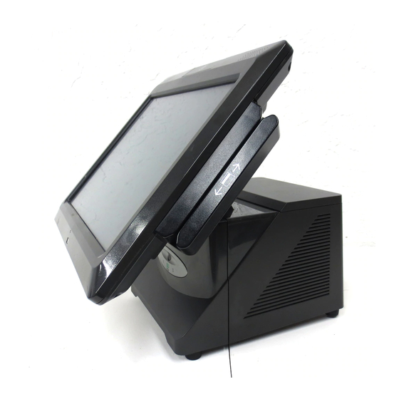
The integration tray supports a variety of NCR’s most popular peripheral options. Desktop Wall Mount... -
Page 13: Model And Serial Number Labels
Display Head, and on the bottom of the Base. If the terminal was shipped with an Operating System pre-installed then there is also a Certificate of Authenticity label on the bottom of the Base. 7403 Display Certification Label NCR Corporation Duluth, GA 30096 Made in Singapore Class 7403 This device complies with Part 15 of the FCC rules. -
Page 14: Features
Chapter 1: Overview Features • Serial ATA (SATA) Hard Drive Interface • High-speed Gigabit Ethernet • Intel AMT 4.0 Remote Management • Proven Capacitive Touch Technology • High Brightness 15” LCD • Stereo Speakers • Motion Detection Sensor • 0 – 90 Degree Display Tilt •... -
Page 15: Motherboard
– Custom ATX12V Power Supply – 80+ Certified – Modular and Serviceable w/o Disconnection of any Cables – Supports NCR Printers Running in 75W Mode – Motherboard • Mobile Intel® GM 45 Express Chipset • Intel® Processors Intel® Core™2 Duo T7500 –... - Page 16 Chapter 1: Overview • Audio – Intel High Definition Audio and HD Codec driving/receiving these interfaces from the backplane (Jack detect support on all ports) Speaker out L/R with 3W/channel amplifier on motherboard. – Headphone out (port can be re-tasked using HD audio) –...
-
Page 17: Cabinet
Chapter 1: Overview Cabinet • Tool-Free Front Accessible Components Motherboard on a Removable Sled – One or Two SATA Hard Drives – DVD ROM Drive – Power Button – • Nine Visible LEDs Lighted Logo to Indicate Power On / Suspend Mode –... -
Page 18: I/O Board
Chapter 1: Overview I/O Board The I/O Board is used to provide external connections to the motherboard. It slides into position in the terminal underneath the motherboard. Line Out Cash Drawer RS232/C RS232/D RS232/A RS232/B 26297b I/O Board Connectors • Ethernet One 10/100/1000 MDI port –... -
Page 19: Powered Serial Port Jumper Settings
Chapter 1: Overview Powered Serial Port Jumper Settings The four serial ports have jumper options for either Ring Indicator (RI), fused +12 V, or fused +5 V on pin 9. When set to powered each port is capable of supporting up to 1.5 A (Max.) and is protected with self‐healing poly‐fuse. The default setting for all four ports is Ring Indicator. 300-15 300-15 300-15 300-15 F4, 3 A, 125 V 26226... - Page 20 1-10 Chapter 1: Overview Additional connectors are located under the Customer Display. Operator Display Cust. Display Power/Audio (+12 V) RS-232 (F) 26130...
-
Page 21: Removing The Display Head From The Base
Chapter 1: Overview 1-11 Removing the Display Head from the Base 1. Disconnect the Display Cable 2. Remove the cable from the Cable Guides. 3. Loosen the Display thumbscrews (2). Display Thumbscrews Display Cable 26150... - Page 22 1-12 Chapter 1: Overview 4. Depress the Display Release Latches (2) as you grasp the edges of the display and slide the Display Head toward the rear of the terminal to disengage it from the chassis. Display Latches 26151...
-
Page 23: Integrated Customer Displays
Chapter 1: Overview 1-13 Integrated Customer Displays The 7403 supports a variety of integrated VFD and LCD customer display. 15" - 5942 LCD - 5964 Touch LCD - 5965 Touch LCD - 5966 Touch LCD 12.1" - 5942 LCD - 5964 Touch LCD 5975 VFD (2 x 20 or APA) 5982 LCD... - Page 24 1-14 Chapter 1: Overview There are four post options for the 5975 display, available in 4 inch increments 26336a...
-
Page 25: Remote Customer Displays
NCR 5975 2x20 VFD Customer Display 22933 The NCR 5975 Customer Display is designed to be an optional display device for the NCR retail terminals. It can also serve as a display for any industry-standard PC. It is a Vacuum Fluorescent Display (VFD). -
Page 26: Character Sets
• Microcontroller • EIA 232 Interface support • USB 2.0 Interface support • Cabinet • UV Stable Material • Available in NCR Light Gray (G-11) and NCR Charcoal Gray (CG1) • Connectors • 9 pin D sub • Powered USB •... -
Page 27: Ncr 5975 Graphical Vfd Customer Display
NCR 5975 Graphical VFD Customer Display 22933 The NCR 5975 Customer Display is designed to be an optional display device for the NCR retail terminals. It can also serve as a display for any industry-standard PC. It is a Vacuum Fluorescent Display (VFD). -
Page 28: Character Sets
Mounting Options • Table Mount, 4-in. Post • Table Mount, 8-in. Post • Table Mount, 12-in. Post • Table Mount, 16-in. Post • Integrated Mount for NCR 7456, 7467, 7458 Character Sets • Support for 21 character sets • 5 Character sets in base unit •... -
Page 29: Software Features
Chapter 1: Overview 1-19 Software Features • Bi-directional parallel interface • Five default character sets: • 16 x 16 or 24 x 24 dots full size JIS 1 and 2 Kanji characters • 8 x 16 or 12 x 24 dots half size ANK characters •... -
Page 30: 5942 12.1-Inch Color Lcd
1-20 Chapter 1: Overview 5942 12.1-Inch Color LCD 19809 The 5942 12.1-Inch LCD is designed for customers who desire a color display and prefer the small footprint and ergonomic packaging of LCD technology versus traditional CRT’s. Depending on the customer’s requirements, this LCD display can be used either as an operator display or a customer information display (CID). -
Page 31: 5964 15-Inch Touch Screen
Chapter 1: Overview 1-21 5964 15-Inch Touch Screen 22041 The NCR 5964-7xxx is a 15-inch XGA (1024x768) Liquid Crystal Display with either a resistive or capacitive Touch Screen for operator input. Features • 15’ LCD XGA (1024x768) native resolution, 350 nit typical brightness (also supports VGA, SVGA, SXGA) •... - Page 32 5964 15-Inch Touch Screen 25819 The NCR 5965 is a 15-inch TFT Liquid Crystal Display with a capacitive Touch Screen. The display accepts industry-standard RGB video images from a PC motherboard and dynamically resizes VGA (640 × 480), SVGA (800 × 600), XGA (1024 × 768) & SXGA (1280 x 1024) @ 60Hz images to fill the entire viewable area.
-
Page 33: Power Supply
Chapter 1: Overview 1-23 Power Supply The power supply provides power to the 7403 Terminal, as well as various retail peripherals through the powered connectors. The power supply is controlled by a logical on/off switch, which permits it to be disabled through software. Other features include: • Auto sensing for 115 VAC/230 VAC operation • Cooling fan Functionally, the terminal’s ON/OFF switch controls the power supply control logic to activate the power supply. This switch does not control actual AC mains voltage applied to the power supply. AC Input The power supply operates with the following voltage ranges. Range Nominal Minimum Maximum Input Current Vrms Vrms Vrms Max. Arms Low (115) 100-127 5.0 A High (230) -
Page 34: Printers
Printers NCR 7167 Printer The NCR 7167 Printer is a fast, quiet, relatively small and very reliable multi-function printer. It prints receipts, validates and prints checks, and prints on a variety of single or multiple part forms. There is not journal as it is kept electronically by the host terminal. The printer can connect through a USB port or a serial port. -
Page 35: Ncr 7168 Printer
Chapter 1: Overview 1-25 NCR 7168 Printer 23446 The 7168 printer is a fast, quiet, relatively small and very reliable multiple-function printer with front and back printing on the receipt paper capability. It prints receipts, validates and prints checks, and prints on a variety of single- or multiple-part forms. There is no journal as it is kept electronically by the host computer. -
Page 36: Power Management
1-26 Chapter 1: Overview Power Management The BIOS supports the supports the Advanced Configuration and Power Management Interface (ACPI) 3.0b specification. A key feature of ACPI is that the operating system, not the BIOS, configures and implements power management. The 7403 terminal supports the Global system power states defined by ACPI: G3 Mechanical Off A computer state that is entered and left by a mechanical means... - Page 37 S1 sleeping state except that the CPU and system cache context is lost (the OS is responsible for maintaining the caches and CPU context). Control starts from the processor’s reset vector after the wake event. In NCR systems, during S3, power is only provided to the on-board USB ports.
-
Page 38: Wake On Lan
1-28 Chapter 1: Overview Wake on LAN The NCR Gold Drives are set up for Wake on LAN from Magic Packet (i.e. specific MAC address) and from Directed Packet. No driver configuration is required. The default is to only wake from standby. To be able to wake from Power Off change the BIOS setting Chipset →... -
Page 39: Chapter 2: Installing The Terminal
Retail IP Web Sites: • Internet: http://www.info.ncr.com • NCR Intranet: http://inforetail.ncr.com To locate the installation guides on these sites: 1. Select General Search. 2. Select the Kit Instructions icon. 3. In the Kit Title field, enter the Kit Title. -
Page 40: Installation Summary
Installation Restrictions • Before installing the terminal, read and follow the guidelines in the NCR RealPOS 70 Site Preparation Guide (B005-0000-1873) and the NCR Workstation and Peripheral AC Wiring Guide (BST0-2115-53). -
Page 41: Connecting The External Cables
Chapter 2: Installing the Terminal Connecting the External Cables Most external cables connect to the I/O Panel and route under the terminal, which is located behind the Front Base Cover. Others connect to the Backplane Board and are routed out the Base Rear Cover. -
Page 42: Accessing The I/O Panel
Chapter 2: Installing the Terminal Accessing the I/O Panel 1. Tilt the Display Module. 26031a 2. Remove the Front Base Cover. a. Insert the Security Key and turn it 90 degrees clockwise. Security Key Front Base Cover 26124a... - Page 43 Chapter 2: Installing the Terminal b. Pivot the top of the Front Base Cover toward the front of the unit and remove it from the terminal. 26032b Line Out Cash Drawer RS232/C RS232/D RS232/A RS232/B...
-
Page 44: Accessing The Backplane Connectors
Chapter 2: Installing the Terminal Accessing the Backplane Connectors 1. Loosen the Captive Screws (2) and remove the Remote Display Base. Captive Screws Remote Display Base +12 V/Audio RS-232 (F) 26926a AC Power Cord Connector 1. Connect the Power Cord to the system and to an AC power source. 2. -
Page 45: Cable Routing
Chapter 2: Installing the Terminal Cable Routing The cables from the I/O Board are routed under the base and out the bottom of the unit. Cables from the Backplane Board are routed out an opening in the Cover and down the back of the terminal. -
Page 46: Terminal Configured With A Dvd-Rom Drive
Chapter 2: Installing the Terminal Terminal Configured with a DVD-ROM Drive If configured with a DVD the cables are routed in the two channels in the bottom of the Base. Route the cables in the channels and under the closed pivoting latches. Secure the cables to the anchor points using Tie Wraps as necessary. -
Page 47: Terminal Without A Dvd-Rom Drive
Chapter 2: Installing the Terminal Terminal without a DVD-ROM Drive If there is no DVD present then there is a Cable Clamp on the front of the Base chassis that is used to secure the cables. 1. Loosen the Cable Clamp Thumbscrew 2. - Page 48 2-10 Chapter 2: Installing the Terminal 3. Route the cable between the clamp and base. 26135b 4. Route the cables in the two channels in the bottom of the Base (as shown on the previous page) and secure them with Tie Wraps as necessary. 5.
-
Page 49: Backplane Cable Routing
Chapter 2: Installing the Terminal 2-11 Backplane Cable Routing 1. Remove the Remote Display Base 2. Connect the cable(s) to the Backplane Board. 3. Route the cable(s) through the opening in the rear of the cabinet and down the back of the terminal to the peripheral device. -
Page 50: Removing The Storage Media
2-12 Chapter 2: Installing the Terminal Removing the Storage Media Squeeze the latch on the green Storage Media Bracket and pull the assembly out of the chassis, which also disconnects it from the Backplane Board. Storage Media (Hard Disk/Solid State Drive) 26034b There are three Storage Media options available for the 7403. -
Page 51: Powering Up The Terminal
An external USB CD-ROM has been certified for staging and maintenance. Other storage devices such as external USB thumb drives may also be used, but none are currently certified, released or supported. To request certification and support for third-party devices, submit your request through the Third-Party Product website (http://www.rsg.ncr.com/tpp/). -
Page 52: Keyboard Support
2-14 Chapter 2: Installing the Terminal Keyboard support The RealPOS 70XRT does not support legacy NCR keyboards and DynaKeys that require PS/2 connections. USB keyboards are supported Connecting peripherals All peripheral ports are color-coded and labeled. All feature self-healing fuses (except for the 24V USB printer port). -
Page 53: Out-Of-Box Failures
During installation if there is an Out of Box failure, the defective component will be replaced. The defective part number must be identified by trained service personnel. If required, contact your Equipment Provider, NCR Customer Service or your Service Provider to diagnose the failure to the component level. - Page 54 2-16 Chapter 2: Installing the Terminal...
-
Page 55: Chapter 3: Touch Screen Calibration
Recalibrate whenever the terminal is moved to a new location. • Recalibrate the touch screen anytime the system has been disassembled for servicing. • Download the Calibration software from the NCR website. http://www.ncr.com a. At this site, select Support. b. Under Related Items, Services; select →... - Page 56 Chapter 3: Touch Screen Calibration 5. Use the USB Controller Interface > Next. 6. Setup is ready to install > > Next Finish At the completion of the install program the driver is loaded and functioning. You do not have to restart your system.
-
Page 57: Calibrating The Touch Screen
Chapter 3: Touch Screen Calibration Calibrating the Touch Screen 1. Run the Hampshire Control Panel → → Programs Hampshire TSHARC Control Panel 2. touch the tab. Calibration The Calibration Tab provides a screen to select which type calibration you prefer. The touch points default to 4-Point Calibration (4 points on the screen to touch). - Page 58 Chapter 3: Touch Screen Calibration a. Touch the center of the target. Pull your finger a few inches away from the screen when you see the Release message. For best results: • Face the monitor directly. • Perform the calibration in the position (sitting or standing) that you normally expect to use the touch screen.
- Page 59 Chapter 3: Touch Screen Calibration d. After touching you are warned to not touch the screen. Accept Touching the screen during this time can cause the Hampshire Application to hang. This screen will automatically close after the touch controller has completed communicating.
-
Page 60: Verifying The Calibration
Chapter 3: Touch Screen Calibration Verifying the Calibration 1. Touch the tab. Tools 2. Touch the button. Drawing Test... - Page 61 Chapter 3: Touch Screen Calibration 3. Test the calibration on the draw screen. Touch the screen in various spots and trace each of the horizontal and vertical lines, including the border around the screen. In this test, all touches are persistent, including touch downs (green dots) and touch ups (red dots).
-
Page 62: Optional Settings
Chapter 3: Touch Screen Calibration Optional Settings After the touch screen is calibrated, adjust the other features to meet your personal preferences. • Double-Click Option • Right-Mouse Click • Touch Modes • Touch Sounds • Tack Bar Pull Up • Touch Offset... -
Page 63: Chapter 4: Installing A Secondary (Dual) Display
This section talks about how to configure dual displays when using the Graphics Media Accelerator Driver or using the Graphics Options controls directly from the Desktop. The controller is included in the NCR Gold Image. There are three ways to open the Intel® Graphics Media Accelerator Driver window: •... -
Page 64: Single Display Mode Setup
Chapter 4: Installing a Secondary (Dual) Display Configuring the Graphics Controller The following display options are available in the Intel Controller: Mode Description Single Display Single display (Notebook or Monitor) - The Monitor selection is only available when a VGA display is attached. Twin Notebook (LCD) and Monitor (VGA) displays with the same video content. -
Page 65: Dual Display Clone Setup (Notebook And Monitor)
Chapter 4: Installing a Secondary (Dual) Display Dual Display Clone Setup (Notebook and Monitor) Note: Twin Operating Mode is set up the same as is Dual Display Clone. 1. Select Intel(R) Dual Display Clone. 2. Select the Primary Device: or Monitor. Notebook 3. -
Page 66: Extended Desktop Dual Display Setup (Notebook And Monitor)
Chapter 4: Installing a Secondary (Dual) Display Extended Desktop Dual Display Setup (Notebook and Monitor) Note: The 7403 display should be the display. To verify this select → Primary Start → Display. Select the Settings tab to display the display IDs. Control Panel 1. -
Page 67: Intel Graphics Controller Hot Keys
Chapter 4: Installing a Secondary (Dual) Display Intel Graphics Controller Hot Keys Hot Keys provide the same functionality as the Intel Graphics Control Panel with specific keystrokes on the keyboard. These hotkeys are listed in the Intel Control Panel under the Hot Keys tab. - Page 68 Chapter 4: Installing a Secondary (Dual) Display...
-
Page 69: Chapter 5: Configuring Amt
Configuring AMT Chapter 5: This chapter explains how to configure an NCR RealPOS 70 so it can be accessed remotely using Intel Management Technology (AMT). Configuring the 7403 Terminal 1. Re-boot the terminal. 2. When you see the message Press DEL to enter setup press to start the utility. - Page 70 Chapter 5: Configuring AMT 3. Under the Advanced tab, select and press [Enter]. Intel AMT Configuration BIOS SETUP UTILITY Main Advanced PCIPnP Boot Security Chipset Exit Advanced Settings Configure CPU. ► CPU Configuration ► IDE Configuration ► SuperIO Configuration ► System Hardware Health Monitoring ►...
- Page 71 F10 Save and Exit ESC Exit 5. Press to Save and Exit. [Enter] 6. During re-boot watch for the following message: Press <CTRL-P> to enter Intel(R)ME Setup This message occurs immediately after the NCR logo disappears. At that moment press Ctrl-P.
- Page 72 [ENTER]=Submit 8. Enter the new password (write it down to remember). The password must contain upper, lower, symbol, & numeric characters. Example: Ncr@2008 You must enter the password twice for verification. 9. Highlight Intel(R) ME Configuration and press [Enter]. Intel (R) Management Engine BIOS Extension v2.1.4.0000 Copyright (C) 2003-06 Intel Corporation.
- Page 73 Chapter 5: Configuring AMT 11. Highlight Intel(R) ME Features Control and press [Enter]. Intel (R) Management Engine BIOS Extension v2.1.4.0000 Copyright (C) 2003-06 Intel Corporation. All Rights Reserved. =======[ INTEL(R) PLATFORM CONFIGURATION ]========== Intel(R) ME State Control Intel(R) ME firmware Local Update Qualifier Intel(R) ME Features Control ►...
- Page 74 Chapter 5: Configuring AMT 13. Highlight Intel(R) AMT and press [Enter]. Intel (R) Management Engine BIOS Extension v2.1.4.0000 Copyright (C) 2003-06 Intel Corporation. All Rights Reserved. ==========[ Intel(R) ME FEATURES CONTROL ]=========== Manageability Features Selection Return to Previous Menu [ESC]=Exit [↑↓]=Select [ENTER]=Access [ ] NONE...
- Page 75 Chapter 5: Configuring AMT 18. At the Main Menu highlight Intel(R) AMT Configuration and press [Enter]. Intel (R) Management Engine BIOS Extension v2.1.4.0000 Copyright (C) 2003-06 Intel Corporation. All Rights Reserved. ==============[ MAIN MENU ]=================== Intel(R) ME Configuration ► Intel(R) AMT Configuration ► Change Intel(R) ME Password Exit [ESC]=Exit...
- Page 76 Chapter 5: Configuring AMT 21. Verify Provision Model is set to Small Business. Highlight Provision Model and press [Enter]. Intel (R) Management Engine BIOS Extension v2.1.4.0000 Copyright (C) 2003-06 Intel Corporation. All Rights Reserved. ===========[ Intel(R) AMT CONFIGURATION ]=========== Host Name TCP/IP Provision Model Setup and Configuration...
-
Page 77: Logging Onto The 7403 Terminal Using Amt
Chapter 5: Configuring AMT Logging onto the 7403 Terminal Using AMT After configuring the 7403 you should now be able to log into it from a browser on a remote 1. Determine the target 7403’s IP address. Windows: → → →... -
Page 78: Removing The Hard Disks
5-10 Chapter 5: Configuring AMT 5. Enter the UserName and Password and then select OK. UserName: admin Password: <your password> The System Status Screen is displayed. You can now control the AMT functions. Removing the Hard Disks If the hard disks are removed both disks must be re-installed in the same slots that Caution: they were removed from in order for Intel ME/AMT features to function correctly. -
Page 79: Chapter 6: Installing Optional Remote Peripherals
Installing Optional Remote Peripherals Chapter 6: Introduction This chapter discusses how to install optional remote peripheral devices. Cable Routing Peripheral cables connect to the I/O Panel behind the Base Front Cover or to the Backplane Board. See the Connecting the External Cables section in the Installing the Terminal chapter for instructions how to access the connectors and how to route the cables. -
Page 80: Usb Installation
Chapter 6: Installing Optional Remote Peripherals USB Installation Connect the Powered USB Printer Interface Cable to the USB Connector and Power Connector on the printer and to the 24 V Powered USB Connector on the terminal. Line Out Cash RS232/ C RS232/ D Drawer RS232/ A... -
Page 81: Rs-232 Installation W/Power From Powered Usb
Chapter 6: Installing Optional Remote Peripherals RS-232 Installation w/Power from Powered USB 1. Connect the RS-232 Printer Interface Cable to the RS-232 Connector on the printer and to an RS-232 Connector on the terminal. 2. Connect the Printer Power Cable to the Power Connector on the printer and to the 24 V Powered USB Connector on the terminal. -
Page 82: Installing A Remote Customer Display
Chapter 6: Installing Optional Remote Peripherals Installing a Remote Customer Display The Standard Remote Mount (5964-K031) is used to mount the following NCR displays. • NCR 5964 15-Inch Touch Monitor • NCR 5942 12.1-Inch Monitor • NCR 5942 15-Inch Monitor •... - Page 83 2. Route the cable(s) down through the mount and out the back of the base. 26474 3. Connect the cable to the proper connector on the host terminal. For more information refer to the NCR 5964 12.1-Inch Touch LCD User's Guide (B005-0000- 1324)
-
Page 84: Ncr 5964 15-Inch Touch Lcd Cable Connections
Chapter 6: Installing Optional Remote Peripherals NCR 5964 15-inch Touch LCD Cable Connections 21496 Note: A PC keyboard is required to configure a 5964 15-Inch Touch LCD. The following illustrations show the cable connections for the 5964 LCD and the 7403 terminal. - Page 85 Chapter 6: Installing Optional Remote Peripherals VGA Connections Connect the LCD Cable to the VGA connectors on both the 5964 LCD and 7403 terminal. 497-0435044 - 1m (1416-C972-0009) 497-0435045 - 4m (1416-C972-0040) 26476...
- Page 86 Line Out Cash RS232/ C RS232/ D Drawer RS232/ A RS232/ B USB/Power 497-0445076 - 1 m 12V USB (1432-C156-0010) 497-0445077 - 4 m (1432-C156-0040) 26475 For more information refer to the NCR 5964 15-Inch Touch LCD User's Guide (B005-0000-1570)
-
Page 87: Ncr 5942 12.1-Inch Lcd Monitor Cable Connections
Chapter 6: Installing Optional Remote Peripherals NCR 5942 12.1-Inch LCD Monitor Cable Connections 19809 The following illustrations show the cable connections for the 5942 12.1” LCD and the 7403 terminal. There are two cables required. • VGA cable for video (supplied with LCD) •... - Page 88 6-10 Chapter 6: Installing Optional Remote Peripherals VGA Connections Connect the LCD Cable to the VGA connectors on both the 5942 12.1” LCD and 7403 terminal. 26478...
- Page 89 7403 terminal. Line Out Cash RS232/ C RS232/ D Drawer RS232/ A RS232/ B Power 12V USB 497-0428512 - 4 m Black (1416-C851-0040) 26477 For more information refer to the NCR 5942 12.1-Inch LCD Monitor User's Guide (B005-0000-1394).
-
Page 90: Ncr 5942 15-Inch Lcd Monitor Cable Connections
6-12 Chapter 6: Installing Optional Remote Peripherals NCR 5942 15-Inch LCD Monitor Cable Connections 21492 The 15” 5942 receives video through the VGA interface. It receives power from an AC power source. • VGA cable for video (supplied with LCD) •... - Page 91 The VGA cable is permanently connected to the 5942 15” LCD. Connect this cable to the VGA connector on the 7403 terminal. AC Power Cord (Country Specific) 26479 For more information refer to the NCR 5942 15-Inch LCD Monitor User Guide (B005-0000-1543)
-
Page 92: Ncr 5965 15-Inch Touch Lcd Cable Connections
6-14 Chapter 6: Installing Optional Remote Peripherals NCR 5965 15-Inch Touch LCD Cable Connections 25819 The following illustrations show the cable connections for the 5965 15” Touch LCD and the 7403 terminal. There are two cables required. • VGA cable for video •... - Page 93 Chapter 6: Installing Optional Remote Peripherals 6-15 VGA Connections Connect the LCD Cable to the VGA connectors on both the 5965 LCD and 7403 terminal. 497-0435044 - 1m (1416-C972-0009) 497-0435045 - 4m (1416-C972-0040) 26480...
- Page 94 Cash RS232/ C RS232/ D Drawer RS232/ A RS232/ B 12V USB 497-0445076 - 1 m 12V USB (1432-C156-0010) 497-0445077 - 4 m (1432-C156-0040) 26481 For more information refer to the NCR 5965 15-Inch Touch LCD Monitor User's Guide (B005-0000-1865).
-
Page 95: Installing An Ncr 5975 Remote Customer Display
Chapter 6: Installing Optional Remote Peripherals 6-17 Installing an NCR 5975 Remote Customer Display There are two models of the NCR 5975 Remote Customer Display: • 5975-1xxx – 2x20 VFD • 5975-2xxx – Graphical VFD 5975-1xxx 2x20 VFD 5975-1xxx Graphical Display 22926 There are four different length posts available, in four inch increments. - Page 96 6-18 Chapter 6: Installing Optional Remote Peripherals 1. Locate the Display Mount within 4 meters (13 ft.) of the host terminal. 2. Determine if the cable should be routed down through the mounting surface or if it should be run on top of the surface. Drill a hole if necessary. 3.
- Page 97 Chapter 6: Installing Optional Remote Peripherals 6-19 5. Route the Interface Cable through the Post and assemble the Post components. 22910...
- Page 98 Connect the I/F cable to a powered RS-232 connector on the terminal. Note: The factory settings for the COM ports are non-powered by default. To change a port to powered see the Circuit Boards chapter in the NCR RealPOS 70 Service Guide, B005-0000-1874.
-
Page 99: Installing A Cash Drawer
Chapter 6: Installing Optional Remote Peripherals 6-21 Installing a Cash Drawer The Cash Drawer can be connected to the Cash Drawer connector or to the transaction printer. Line Out Cash Drawer RS232/ C RS232/ D RS232/ A RS232/ B Cash Drawer Cash Drawer Connector 26244... -
Page 100: Installing A Second Cash Drawer
6-22 Chapter 6: Installing Optional Remote Peripherals Installing a Second Cash Drawer The terminal also supports a 2-drawer configuration using a Y-cable (1416-C372-0006) connected to the printer. 1. Place the cash drawer in the desired location, within cable's length of the printer. 2. -
Page 101: Chapter 7: Installing A Raid System
The RAID circuitry is located on the Motherboard. The necessary drivers are included in the NCR Gold Images. You can configure either a RAID Mirrored or RAID Striping Volume. For more information about The Intel Matrix Storage Manager see the Intel® web site. - Page 102 Chapter 7: Installing a RAID System 5. From the View menu select Advanced Mode. 6. From the Actions menu select Create RAID volume from Existing Hard drive.
- Page 103 Chapter 7: Installing a RAID System 7. Select at the Welcome screen. Next 8. Enter a Volume Name (user preference). 9. Select the type of RAID volume you want to install. NCR supports RAID 0 and RAID 1 volume types. • RAID 0: Striped Set without parity: provides improved performance and additional storage but no fault tolerance from disk errors or disk failure.
- Page 104 Chapter 7: Installing a RAID System • RAID 1: Mirrored Set without parity: provides fault tolerance from disk errors and single disk failure. Increased read performance occurs when using a multi-threaded operating system that supports split seeks, very small performance reduction when writing.
- Page 105 Chapter 7: Installing a RAID System 11. Select the correct Member drive from the list of available drives and move it to the right side window using the arrow button. Select Next. 12. RAID 0 Only: Specify the amount of available space to be used by the new RAID volume.
- Page 106 Chapter 7: Installing a RAID System 13. Select to start the volume migration. This can take 1 – 3 hours to complete. Next 14. A progress bar is displayed as the RAID volume is created. Note: If the above progress screen gets deleted you can monitor the status from the Basic Mode in the Matrix Storage Manager.
-
Page 107: Replacing A Failed Raid 1 (Mirrored) Hdd
Chapter 7: Installing a RAID System Replacing a Failed RAID 1 (Mirrored) HDD If a hard drives fails the Matrix software detects the failure and displays a RAID Volume Degraded warning message. 1. Click on the message icon to determine which drive failed. This opens the Matrix Storage Manager and displays the drive statuses. -
Page 108: Raid Option Rom
Chapter 7: Installing a RAID System RAID Option ROM The Intel RAID Option ROM provides a pre-operating system user interface for configuring Intel® RAID Technology. It is integrated with the system BIOS on the motherboard. The Intel RAID option ROM is enabled when the Intel RAID Technology is enabled in the system BIOS setup. -
Page 109: Chapter 8: 2X20 Customer Display Interface
2x20 Customer Display Interface Chapter 8: Introduction The 2x20 Customer Display consists of a Vacuum Florescent Display (VFD) with two rows of twenty 5x8 dot matrix characters, an RS-232 serial interface, driver circuitry, DC to DC/AC converter, and a character generator. General Specifications Item Value... -
Page 110: Command Codes
Chapter 8: 2x20 Customer Display Interface Command Codes User Defined Character Definition (08h, CODE, Byte1…Byte5) This command defines a user defined character (UDC). The UDC character code is set by the CODE byte and must be 00H to 07H. All other values for CODE will be ignored by this command. -
Page 111: Clear Display (12H)
Chapter 8: 2x20 Customer Display Interface Clear Display (12h) This command sets all 40 characters to 20h (space) and moves the cursor to the first position of the top line. Luminance Control (11h, LUMINANCE) This command selects the display luminance. The LUMINANCE byte sets the display luminance level as defined in the table below. -
Page 112: Cp437
Chapter 8: 2x20 Customer Display Interface CP437... -
Page 113: Cp858
Chapter 8: 2x20 Customer Display Interface CP858... -
Page 114: Cp866
Chapter 8: 2x20 Customer Display Interface CP866... -
Page 115: Cp932
Chapter 8: 2x20 Customer Display Interface CP932... -
Page 117: Chapter 9: Cash Drawer Interface
Cash Drawer Interface Chapter 9: Customers/partners needing cash drawer interface information should contact their NCR representative. - Page 118 Chapter 9: Cash Drawer Interface...
-
Page 119: Chapter 10: Wedge To Usb Msr Software Migration
Wedge to USB MSR Software Migration Chapter 10: Overview The purpose of this chapter is to explain configuration and software installation changes that are required to migrate your OPOS/JavaPOS application from a Wedge MSR to a USB MSR. Note: This only applies to OPOS/JavaPOS applications running in Windows Operating Systems. -
Page 120: Software Requirements
NCRMSR.3 profile showing the proper configuration options for using the USB MSR. [HKEY_LOCAL_MACHINE\SOFTWARE\OLEforRetail\ServiceOPOS\MSR\NCRMSR.3] @="NCRFitClient.MSR" "Description"="NCR 74XX MSR Service Object" "MSR"="USB" "NCRVersion"="2.4.1.0 -> NCR Release File Version" "ProductID"="0 -> ProductID: Maximum 0xFFFF hex" "TimeOut"="800" "Type"="ISO" "VendorID"="0 -> VendorID: Maximum 0xFFFF hex" "Version"="1.3.0"... -
Page 121: Potential Operational Differences
RPSW can be installed silently from a command line using parameters to install the necessary NCR5932 feature. INSTALLOPOS_SO_5932=YES Full details on the command line information can be found on the NCR Support Website. Download the RPSW files (D370-0782-0100_03.00.01.00.zip). See the Command Line Parameters for Retail Platform Software for Windows. - Page 122 10-4 Chapter 10: Wedge to USB MSR Software Migration...
-
Page 123: Chapter 11: Maintenance
Maintenance Chapter 11: Cabinet and Touch Screen Cleaning Procedures 1. Disconnect the unit from the power outlet before cleaning. 2. Use a soft cloth dampened lightly with a mild non-abrasive soap & water solution or 70% Isopropyl Alcohol. 3. Gently wipe the subject area clean. 4. -
Page 124: Cooling Vent Cleaning
11-2 Chapter 11: Maintenance Cooling Vent Cleaning The air vents on the side of the terminal should be cleaned periodically to maintain optimum cooling for the CPU. Procedure 1. Shut the system down and disconnect the AC power cord. 2. Use the hose attachment on a standard household vacuum cleaner to remove the dust from the vents. -
Page 125: Msr Cleaning Procedures
MSR Cleaning Cards and MSR Treatment Cards may be purchased from NCR or KIC Products. For details, see http://www.ncr-direct.com... - Page 126 11-4 Chapter 11: Maintenance...
-
Page 127: Chapter 12: Operating System Recovery
Teac USB External CD-ROM Drive (2336-K208) • NCR Services: External CDR/W DVD-ROM Drive (603-9014774) • Network (See the NCR FitClient Software User's Guide, B005-0000-1235.) Prerequisites The following are required in order to perform an OS recovery from a CD. •... -
Page 128: Connecting An External Cd-Rom Drive
12-2 Chapter 12: Operating System Recovery Connecting an External CD-ROM Drive If your terminal contains an integrated CD-ROM, skip to OS Recovery Procedures. 1. Connect the external CD-ROM drive to the USB connector on the terminal. Line Out Cash Drawer RS232/ C RS232/ D RS232/ A... -
Page 129: Os Recovery Procedures
2. Connect a keyboard to the terminal. 3. Apply power to the terminal. 4. Press during boot (when you see the NCR logo) to enter the Boot Select menu. [F8] 5. If you are using the integrated CD/DVD Drive select CD/DVD:P1-DV-28S-V. - Page 130 12-4 Chapter 12: Operating System Recovery 10. At the following prompt replace the CD with the next CD. Press to continue. [Enter] Automatic mount +------+ +------+ Please, press “ok” to mount [/dev/cdrom] on [mnt/cdrom] +----+ +----+ +-------------------------------+ 11. Repeat the previous step for each CD as required. 12.
-
Page 131: Chapter 13: Bios Updating Procedures
• Bootable CD • Bootable USB Memory Drive • Network – Refer to the NCR FitClient Software User's Guide, (B005-0000-1235) for information about this procedure. Prerequisites The following are required to perform a SPI/BIOS update. • Bootable USB CD-ROM Drive •... -
Page 132: Creating The Bootable Media
13-2 Chapter 13: BIOS Updating Procedures Creating the Bootable Media Creating a Bootable CD The downloaded file is a CD image file (ISO) containing the files necessary to create a bootable CD. A system with a CD/DVD burner is required to perform this function. 1. -
Page 133: Spi/Bios Updating Procedures
You can change the boot order temporarily in the BIOS Setup Boot Menu or you can press during boot (when you see [F8] the NCR logo) to enter the Boot Select menu. • If you are using the integrated CD/DVD Drive select CD/DVD:P1-DV-28S-V. •... - Page 134 13-4 Chapter 13: BIOS Updating Procedures Option 1 – Update SPI and BIOS – No prompt for Serial/Model/Class unless invalid 1. Highlight Option 1 and press [ENTER]. (Executes automatically in 10 seconds unless the up/down arrow is pressed.) 2. The Flash Program updates the SPI/BIOS, automatically powers down, and then reboots the terminal.
- Page 135 Chapter 13: BIOS Updating Procedures 13-5 Option 4 – Update of SPI and BIOS – Always prompts for Serial/Model/Class This option is similar to Option 1 above except you are prompted for Class/Model/Serial information at the beginning of the program. You also have to select which type of update to run, BIOS or SPI.
- Page 136 13-6 Chapter 13: BIOS Updating Procedures Option 5 – Update of BIOS only – Always prompts for Serial/Model/Class This option prompts for Class/Model/Serial information at the beginning of the program and then updates the BIOS only. 1. Highlight Option 5 and press [ENTER]. 2.
- Page 137 Chapter 13: BIOS Updating Procedures 13-7...
-
Page 139: Chapter 14: Bios Settings
1. Connect an alphanumeric USB keyboard to the terminal. 2. Apply power to the terminal. 3. When you see the NCR logo displayed press [Del]. How to Select Menu Options The following keyboard controls are used to select the various menu options and to make changes to their values. -
Page 140: Bios Default Values
14-2 Chapter 14: BIOS Settings BIOS Default Values BIOS Version: 6.2.4.0 Main Menu (variable) System Time (variable) System Date Advanced Menu CPU Configuration Hardware Prefetcher [Enabled] Adjacent Cache Line Prefetch [Enabled] Max CPUID Value Limit [Disabled] Execute-Disable Bit Compatibility [Enabled] Intel(R) SpeedStep(tm) tech [Enabled] Intel(R) C-STATE tech... - Page 141 Chapter 14: BIOS Settings System Hardware Health Monitoring Motherboard HHM I/O Board HHM ACPI Configuration General ACPI Configuration Suspend Mode [Auto] Repost Video on S3 Resume [No] Advanced ACPI Configuration ACPI Version Features [ACPI v3.0] ACPI APIC support [Enabled] AMI OEMB table [Enabled] Headless mode [Disabled]...
- Page 142 14-4 Chapter 14: BIOS Settings S.M.A.R.T. [Enabled] AHCI Port4 [ATAPI CDROM] SATA Port4 [Auto] AHCI Port5 [Not Detected] SATA Port5 [Auto] S.M.A.R.T. [Enabled] ASF Configuration ASF Support [Enabled] Event Log Configuration View Event Log Mark all event as read Clear Event Log Intel AMT Configuration Intel AMT Support [Disabled]...
-
Page 143: Pci/Pnp Menu
Chapter 14: BIOS Settings PCI/PnP Menu [No] Clear NCRAM [No] Plug & Play O/S [64] PCI Latency Timer [Yes] Allocate IRQ to PCI VGA [Disabled] Palette Snooping [Disabled] PCI IDE BusMaster [Auto] OffBoard PCI IDE Card [Available] IRQ3 [Available] IRQ4 [Available] IRQ5 [Available]... -
Page 144: Boot Menu
14-6 Chapter 14: BIOS Settings Boot Menu Boot Settings Configuration Quick Boot [Disabled] Quiet Boot [Enabled] AddOn RoM Display Mode [Force BIOS] Bootup Num=Lock [On] PS/2 Mouse Support [Disabled] Wait For ‘F1’ If Error [Disabled] Hit ‘DEL’ Message Display [Enabled] Interrupt 19 Capture [Disabled] Boot Type... -
Page 145: Chipset Menu
Chapter 14: BIOS Settings Chipset Menu NorthBridge Configuration Memory Hole [Disabled] Boots Graphic adapter Priority [PEG/PCI] Internal Graphics Mode Select [Enabled, 32MB] Max TOLUD [3G Bytes] Gfx Low Power Mode [Enabled] PEG Port configuration PEG Port [Auto] Video Function Configuration DUMT Mode Select [DUMT Mode] DUMT/FIXED Memory... - Page 146 14-8 Chapter 14: BIOS Settings PCIE Port 2 [Enabled] PCIE Port 3 [Enabled] PCIE Port 4 [Enabled] PCIE High Priority Port [Disabled] PCIE Port 0 IOxAPIC Enable [Disabled] PCIE Port 1 IOxAPIC Enable [Disabled] PCIE Port 2 IOxAPIC Enable [Disabled] PCIE Port 3 IOxAPIC Enable [Disabled] PCIE Port 4 IOxAPIC Enable...
-
Page 147: Acpi Bios
Memory Map Appendix A: ACPI BIOS 6.2.3.0 FFFF:000F PC BIOS E400:0000 Reserved for PC BIOS E000:0000 = Can Be Overlaid Free Space = ROMs that are not present if DISABLED in the BIOS D680:0000 PXE Option ROM D480:0000 RAID Option ROM (20 K) CF80:0000 VGA Video BIOS (62 K) C000:0000... - Page 148 Appendix A: Memory Map...
-
Page 149: Appendix B: Irq Settings
IRQ Settings Appendix BIOS Version 1.0.0.0 Interrupts Default Settings System Resource IRQ Priority Reserved COM B/2F8 COM A/3F8 COM E/2E0 Real Time Clock COM D/2E8 COM C/3E8 Available/PS/2 Mouse Co-CPU IDE 1 (IDE Mode only) IDE 2 (IDE Mode only) PCI Devices Video, USB1, USB2, USB3, (Require 1...
Need help?
Do you have a question about the RealPOS 70XRT and is the answer not in the manual?
Questions and answers