Sign In
Upload
Download
Table of Contents
Contents
Add to my manuals
Delete from my manuals
Share
URL of this page:
HTML Link:
Bookmark this page
Add
Manual will be automatically added to "My Manuals"
Print this page
×
Bookmark added
×
Added to my manuals
Manuals
Brands
MacDon Manuals
Tractor
9250
Operator's manual
MacDon 9250 Operator's Manual
Self-propelled windrower
Hide thumbs
1
2
3
Table Of Contents
4
5
6
7
8
9
10
11
12
13
14
15
16
17
18
19
20
21
22
23
24
25
26
27
28
29
30
31
32
33
34
35
36
37
38
39
40
41
42
43
44
45
46
47
48
49
50
51
52
53
54
55
56
57
58
59
60
61
62
63
64
65
66
67
68
69
70
71
72
73
74
75
76
77
78
79
80
81
82
83
84
85
86
87
88
89
90
91
92
93
94
95
96
97
98
99
100
101
102
103
104
105
106
107
108
109
110
111
112
113
114
115
116
117
118
119
120
121
122
123
124
125
126
127
128
129
130
131
132
133
134
135
136
137
138
139
140
141
142
143
144
145
146
147
148
149
150
151
152
153
154
155
156
157
158
159
160
page
of
160
Go
/
160
Contents
Table of Contents
Troubleshooting
Bookmarks
Table of Contents
Introduction
Table of Contents
Serial Number Locations
Safety
Safety Alert Symbol
Signal Words
Safety Signs
General Farm Safety
Specifications
Tractor
Hardware Torque Specifications
Hydraulic Fitting Torque Specifications
Engines
Operator's Station
Symbol Definitions
Mac Monitor
Operator Presence System
Gauges
Speedometer
Ignition Switch
Lights
Cab Temperature Controls
Windshield Wiper Control
Windrower Controls
Header Controls
Seat Belts
Seat Adjustments
Operator Amenities
Operation
Your Responsibilities as an Owner/Operator
To the New Operator
Break-In Period
Pre-Starting Checks: Annual
Pre-Starting Checks: Daily
Start-Up Procedure
Driving the Windrower
Safety
To Drive Forward
To Drive Rearward
Making a Spin Turn
Stopping Procedure
To Stop Windrower
To Stop Engine
Leaving the Windrower
Emergency Exit
Attaching the Header
Adding Rear Weight
Detaching the Header
Operating the Header
Header Lift Cylinder Stops
Header Angle
Header Levelling
Header Flotation
Transporting the Windrower
Driving on Roads
Transporting the Windrower (Continued)
Towing with a Trailer
Towing Without a Trailer
Storage Procedure
Service Procedures
Maintenance/Service
Seat Belt Inspection and Maintenance
Operator Presence System
R/H Step Ladder Use & Storage
Fuels, Fluids and Lubricants
Diesel Fuel
Engine Coolant
Grease
Hydraulic Oil
Engine Oil
Bevel Gear Box Lubricant
Power Wheel Gear Lubricant
Storing Lubricants
System Capacities
Greasing the Windrower Tractor
Cummins Barring Tool
Opening and Closing Hood
Lubricating Oil
Diesel Engine
Belts
Engine Speed: Throttle Rod Adjustment (Naturally Aspirated)
Engine Speed: Throttle Rod Adjustment (Turbo)
Valve Tappet Clearance
General Engine Inspection
Diesel Engine Air Intake System: Air Cleaner
Diesel Engine Fuel System Storing Fuel
Refuelling Windrower
Fuel Tank Venting
Fuel Sediment Bowl
Fuel Water Separator
Fuel Filters
Fuel System Air Removal
Engine Exhaust System: Muffler
Engine Cooling System Coolant Level
Radiator Cap
Anti-Freeze Concentration
Changing Coolant
Screens and Coolers
Electrical System Battery
Preventing Alternator and Regulator Damage
Lights and Bulbs
Replacing Gauge Light Bulbs
Replacing Dome Light Bulb
Replacing Turn Signal Indicators
Circuit Breakers
Hydraulic System
Safety
Hydraulic Oil Cooler
Hydraulic Oil & Filters
MAINTENANCE/SERVICE (Continued)
Hydraulic System: Header & Reel Lift
Cylinder Control Valve Relief Pressure
Header Drive: Hydraulics
Flow Control Block
Header Drive Relief Pressure
Header Drive
Bevel Gear Box Lubricant
Header Drive Belt
Header Drive Bevel Gear Box Lubricant
Header Drive Belt Pulley Alignment
Header Drive Belt Guides & Pulley Shield
Traction Drive: Hydraulics
Transmission Oil Pressure
Charge Pump Pressure
Checks
Traction Drive: Neutral Lock and Steering
Troubleshooting
Neutral Set-Up Procedure
Traction Drive
Ground Speed Lever Friction Device
Wheels and Tires
Park Brake (Models 9250/9350, 4940/4950, 2940/2950, 8140/8150)
Park Brake (Models 9352, 4952, 2952, 8152)
Cab Air System
Maintenance Schedule
Maintenance Record
Trouble Shooting
Cab Air System
Engine
Electrical
Traction Drive System
Steering and Ground Speed Controls
Header Hydraulics
Header Drive
Park Brake
Operator's Seat
Options and Attachments
Unloading
Assembly
Tires
Battery
Adjustments & Checks
Preparing for Harvest Headers
Radio & Two-Way Radio Installation
Tool Box
Swath Roller Installation
Index
Electrical & Hydraulic Schematics
Advertisement
Quick Links
Download this manual
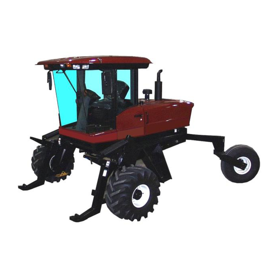
9250/9350/9352
SELF-PROPELLED
WINDROWER
OPERATOR'S MANUAL
Form 46584 Issue 11/06 Web Rev_01
Sugg. Retail: $25.00
Table of
Contents
Previous
Page
Next
Page
1
2
3
4
5
Advertisement
Table of Contents
Troubleshooting
Traction Drive: Neutral Lock and Steering
103
TROUBLE SHOOTING
119
Need help?
Do you have a question about the 9250 and is the answer not in the manual?
Ask a question
Questions and answers
Related Manuals for MacDon 9250
Tractor MacDon 9352 Operator's Manual
Self-propelled windrower (160 pages)
Tractor MacDon 9350 Operator's Manual
Self-propelled windrower (160 pages)
Tractor MacDon M150 Operator's Manual
Macdon self-propelled windrower operator's manual (234 pages)
Tractor MacDon M150 Assembly Instructions Manual
Macdon self-propelled windrower unloading and assembly instructions (55 pages)
Tractor MacDon M105 Operator's Manual
Macdon m105 self-propelled windrower, tractor (209 pages)
Tractor MacDon M Series Unloading And Assembly Instructions
Self-propelled windrower m series; (95 pages)
Tractor MacDon M155 Operator's Manual
Self-propelled windrower (510 pages)
Tractor MacDon M205 Operator's Manual
Self-propelled windrower (514 pages)
Tractor MacDon M1170 Assembly Instructions Manual
Windrower (142 pages)
Tractor MacDon M150 2009 Setup Instruction
Double windrow attachment (41 pages)
Tractor MacDon M155E4 2016 Manual
Self-propelled windrower (184 pages)
Tractor MacDon M2170NT Unloading And Assembly Instructions
Narrow transport windrower (266 pages)
This manual is also suitable for:
9352
9350
Table of Contents
Save PDF
Print
Rename the bookmark
Delete bookmark?
Delete from my manuals?
Login
Sign In
OR
Sign in with Facebook
Sign in with Google
Upload manual
Upload from disk
Upload from URL


Need help?
Do you have a question about the 9250 and is the answer not in the manual?
Questions and answers