MacDon M205 Operator's Manual
Self-propelled windrower
Hide thumbs
Also See for M205:
- Installation instructions manual (30 pages) ,
- Maintenance and service manual (2 pages) ,
- Unloading and assembly instructions (396 pages)

Related Manuals for MacDon M205


Summary of Contents for MacDon M205
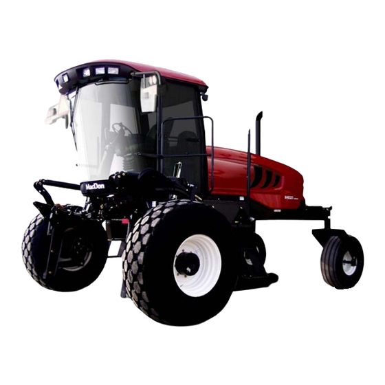
- Page 1 M205 Self-Propelled Windrower Operator’s Manual 214603 Revision A 2018 Model Year Original Instruction The harvesting specialists.
- Page 2 ® ® M205 Self-Propelled Windrower, featuring Dual Direction and Ultra Glide suspension. Published March, 2018 California Proposition 65 Warning Diesel engine exhaust and some of its constituents are known to the State of California to cause cancer, birth defects, and other reproductive harm. Battery posts, terminals, and related accessories contain lead and lead components.
- Page 3 Declaration of Conformity...
- Page 5 This manual contains information on the MacDon M205 Self-Propelled Windrower which, when coupled with one of MacDon’s auger, rotary, or draper headers, provides a package designed to cut and lay in windrows a variety of grain, hay, and specialty crops.
- Page 6 List of Revisions At MacDon, we’re continuously making improvements: occasionally these improvements impact product documentation. The following list provides an account of major changes from the previous version of this document. Summary of Change Location Changed the publication part number from 147955 to —...
- Page 7 7.3.11 Swath Compressor, page 447 chapter. Added Recommended Fluids and Lubricants to the — inside back cover. Removed Pre-cleaner and Sweeps kit (B6422) from — Options and Attachments chapter; the kit is not applicable to 2018 M205 Windrowers. 214603 Revision A...
-
Page 8: Serial Numbers
Serial Numbers If you require MacDon technical assistance, please have the serial numbers recorded and ready before you call. Record the model number, model year, and serial number of the windrower and engine on the lines below. The windrower serial number plate (A) is located on the left side of the main frame near the walking beam. -
Page 9: Table Of Contents
TABLE OF CONTENTS Introduction..............................i List of Revisions ............................ii Serial Numbers ............................iv Chapter 1: Safety ............................ 1 1.1 Safety Alert Symbols ..........................1 1.2 Signal Words ............................2 1.3 General Safety.............................3 1.4 Maintenance Safety ..........................5 1.5 Hydraulic Safety...........................6 1.6 Tire Safety............................7 1.7 Battery Safety ............................8 1.8 Welding Precautions ..........................9 1.9 Engine Safety ............................10... - Page 10 TABLE OF CONTENTS 3.4 Training Seat .............................46 3.5 Using Seat Belts ..........................47 3.6 Adjusting Steering Column .........................48 3.7 Exterior Lighting..........................49 3.7.1 Field Light: Cab-Forward ......................50 3.7.2 Road Light: Engine-Forward ......................51 3.7.3 Road Light: Cab-Forward......................52 3.7.4 Hazard Light ..........................53 3.7.5 Beacon Light (Optional) ......................53 3.7.6 Auto Road Light ........................54 3.7.7 HID Auxiliary Lighting (Optional)....................54 3.8 Windshield Wipers ..........................56...
- Page 11 TABLE OF CONTENTS Engine Running – At Initial Start Up ...................78 Engine-Forward, Engine Running ....................79 Cab-Forward, Engine Running, Header Disengaged ..............79 Cab-Forward, Engine Running, Header Engaged, Auger Header Index Switch OFF ......80 Cab-Forward, Engine Running, Header Engaged, Auger Header Index Switch ON......81 Cab-Forward, Engine Running, Header Engaged, Draper Header, Index Switch OFF ....82 Cab-Forward, Engine Running, Header Engaged, Draper Header Index Switch ON ......83 Cab-Forward, Engine Running, Header Engaged, Rotary Header Installed ........84...
- Page 12 TABLE OF CONTENTS Displaying the Windrower and Engine Error Codes ..............133 Switching the Installed Header Sensors ON or OFF ..............134 Displaying Header Sensor Input Signals................... 136 Forcing a Header ID........................ 137 3.19.14 Troubleshooting Header Problems..................139 Testing the Header Up/Down Activate Function Using the Cab Display Module (CDM)....139 Testing the Reel Up/Down Activate Function Using the Cab Display Module (CDM).....
- Page 13 TABLE OF CONTENTS Stopping ..........................177 4.3.7 Adjusting Caster Tread Width....................177 4.3.8 Transporting ........................... 179 Driving on the Road ........................ 179 Towing Header with Windrower....................181 Towing the Windrower (Emergency)..................192 Disengaging Final Drives ......................192 4.3.9 Storing the Windrower ......................193 4.4 Operating with a Header ........................
- Page 14 TABLE OF CONTENTS Attaching an R Series Header: Hydraulic Center-Link and Optional Self-Alignment...... 249 Attaching an R Series Header: Hydraulic Center-Link without Optional Self-Alignment....254 4.5.7 Detaching an R Series Header ....................259 Detaching an R Series Header: Hydraulic Center-Link............... 259 4.6 Operating with a D Series or D1 SP Series Header ................
- Page 15 TABLE OF CONTENTS 5.4.1 Lubricating the Windrower ....................... 293 5.4.2 Lubrication Points........................294 5.5 Operator’s Station ..........................295 5.5.1 Seat Belts..........................295 5.5.2 Safety Systems ........................295 Checking Operator Presence System ..................295 Checking Engine Interlock....................... 296 5.5.3 Ground Speed Lever (GSL) Adjustments .................. 296 Adjusting Ground Speed Lever (GSL) Lateral Movement............
- Page 16 TABLE OF CONTENTS Installing Primary Fuel Filter ....................326 Removing Secondary Fuel Filter ....................326 Installing Secondary Fuel Filter....................327 Draining Fuel Tank........................328 Fuel/Water Separator......................329 Removing Water from Fuel System ..................329 System Priming ........................330 Priming Fuel System....................... 330 5.8.6 Engine Cooling System ......................
- Page 17 TABLE OF CONTENTS Adjusting Forward Floodlights....................363 Replacing Bulb in Cab-Forward Flood Light ................363 5.9.6 High-Intensity Discharge (HID) Auxiliary Lighting (Optional – MD #B5596) ........365 Adjusting High-Intensity Discharge (HID) Auxiliary Lights (if Installed)......... 365 Replacing High-Intensity Discharge (HID) Auxiliary Lights (if Installed) ........366 5.9.7 Floodlights: Rear........................
- Page 18 TABLE OF CONTENTS Changing Wheel Drive Lubricant....................402 Servicing Drive Wheel......................403 Raising Drive Wheel ....................... 403 Removing Drive Wheel ......................404 Installing Drive Wheel ......................405 Lowering Drive Wheel......................406 5.11.2 Caster Wheels........................406 Inflating Caster Tire ........................ 406 Tightening Caster Wheel Nuts ....................
- Page 19 TABLE OF CONTENTS 7.3.1 Spring with External Booster Spring..................446 7.3.2 Spring with Internal Booster Spring................... 446 7.3.3 Completion Kit for Auger and Draper Header Drives ..............446 7.3.4 Completion Kit for Auger Header Drive and Conditioner Reverser ..........446 7.3.5 Completion Kit for Draper Header Reel Drive................
-
Page 21: Chapter 1: Safety
1 Safety 1.1 Safety Alert Symbols This safety alert symbol indicates important safety messages in this manual and on safety signs on the machine. This symbol means: • ATTENTION! • BECOME ALERT! • YOUR SAFETY IS INVOLVED! Carefully read and follow the safety message accompanying this symbol. -
Page 22: Signal Words
SAFETY 1.2 Signal Words Three signal words, DANGER, WARNING, and CAUTION, are used to alert you to hazardous situations. Signal words are selected using the following guidelines: DANGER Indicates an imminently hazardous situation that, if not avoided, will result in death or serious injury. WARNING Indicates a potentially hazardous situation that, if not avoided, could result in death or serious injury. -
Page 23: General Safety
SAFETY 1.3 General Safety CAUTION The following are general farm safety precautions that should be part of your operating procedure for all types of machinery. Protect yourself. • When assembling, operating, and servicing machinery, wear all protective clothing and personal safety devices that could be necessary for job at hand. - Page 24 SAFETY • Wear close-fitting clothing and cover long hair. Never wear dangling items such as scarves or bracelets. • Keep all shields in place. NEVER alter or remove safety equipment. Make sure driveline guards can rotate independently of shaft and can telescope freely. •...
-
Page 25: Maintenance Safety
SAFETY 1.4 Maintenance Safety To ensure your safety while maintaining machine: • Review operator’s manual and all safety items before operation and/or maintenance of machine. • Place all controls in Neutral, stop the engine, set the park brake, remove the ignition key, and wait for all moving parts to stop before servicing, adjusting, and/or repairing. -
Page 26: Hydraulic Safety
SAFETY 1.5 Hydraulic Safety • Always place all hydraulic controls in Neutral before dismounting. • Make sure that all components in hydraulic system are kept clean and in good condition. • Replace any worn, cut, abraded, flattened, or crimped hoses and steel lines. •... -
Page 27: Tire Safety
SAFETY 1.6 Tire Safety WARNING • Service tires safely. • A tire can explode during inflation which could cause serious injury or death. • Follow proper procedures when mounting a tire on a wheel or rim. Failure to do so can produce an explosion that may result in serious injury or death. -
Page 28: Battery Safety
SAFETY 1.7 Battery Safety WARNING • Keep all sparks and flames away from batteries, as a gas given off by electrolyte is explosive. • Ventilate when charging in enclosed space. Figure 1.16: Safety around Batteries WARNING • Wear safety glasses when working near batteries. •... -
Page 29: Welding Precautions
SAFETY 1.8 Welding Precautions High currents and voltage spikes associated with welding can cause damage to electronic components. Before welding on any part of windrower or an attached header, disconnect all electronic module harness connections as well as battery cables. Refer to your Dealer for proper procedures. 214603 Revision A... -
Page 30: Engine Safety
SAFETY 1.9 Engine Safety WARNING Do NOT use aerosol starting aids such as ether. Such use could result in an explosion and personal injury. CAUTION • On initial start-up of a new, serviced, or repaired engine, always be ready to stop the engine in order to stop an overspeed. -
Page 31: Engine Electronics
SAFETY 1.9.2 Engine Electronics WARNING Tampering with electronic system installation or original equipment manufacturer (OEM) wiring installation can be dangerous and could result in personal injury or death and/or engine damage. WARNING Electrical Shock Hazard. The electronic unit injectors use DC voltage. The engine control module (ECM) sends this voltage to the electronic unit injectors. -
Page 32: Safety Signs
• Replacement safety signs are available from your MacDon Dealer Parts Department. Figure 1.19: Operator’s Manual Decal 1.10.1 Installing Safety Decals 1. Clean and dry installation area. 2. Decide on exact location before you remove decal backing paper. -
Page 33: Safety Sign Locations
SAFETY 1.11 Safety Sign Locations Figure 1.20: Safety Sign Locations (Left Cab-Forward Side) F G H A - Hazard Sign (MD #135378) B - Cab Door and Rim (MD #166454) C - Oil Reservoir under Hood (MD #166466) D - Exhaust Cover (MD #166450) E - Close to Radiator Cap (MD #166461) F - Fan Shroud (Top) (MD #166450) G - Fan Shroud (Middle) (MD #166451) - Page 34 SAFETY Figure 1.21: Safety Signs (Left Cab-Forward Side) 214603 Revision A...
- Page 35 SAFETY Figure 1.22: Safety Sign Locations (Right Cab-Forward Side) A - Hazard Sign on Seat (MD #115148) B - Lift Linkage (MD #166439) C - Frame (MD #166455) D - Frame (MD #166456) E - Cab Frame (MD #184372) F - Platform (MD #166425) G - Shroud (MD #166451) H - Shroud (MD #166452) J - Hydraulic Reservoir (MD #174436)
- Page 36 SAFETY Figure 1.23: Safety Signs (Right Cab-Forward Side) 214603 Revision A...
-
Page 37: Understanding Safety Signs
SAFETY 1.12 Understanding Safety Signs MD #166233 Run-over hazard DANGER • Do not start engine by shorting across starter or starter relay terminals. Machine will start with drive engaged and move if starting circuitry is bypassed. • Start engine only from operator’s seat. Do not try to start engine with someone under or near machine. - Page 38 SAFETY MD #166438 Crushing hazard DANGER • Rest header on ground or engage safety props before going under unit. Figure 1.27: MD #166438 MD #166439 Crushing hazard DANGER • Rest header on ground or engage safety props before going under unit. Figure 1.28: MD #166439 214603 Revision A...
- Page 39 SAFETY MD #166441 Loss of control hazard CAUTION • To prevent machine damage and/or loss of control, it is essential that the machine be equipped such that weights are within the specified limits. Figure 1.29: MD #166441 MD #166450 Hot surface hazard WARNING •...
- Page 40 SAFETY MD #166454 General hazard pertaining to machine operation and servicing CAUTION • Read the operator’s manual and follow all safety instructions. • Do not allow untrained persons to operate the machine. • Review safety instructions with all Operators every year. •...
- Page 41 SAFETY MD #166456 Battery acid hazard WARNING • Corrosive and poisonous battery acid. Acid can severely burn your body and clothing. Figure 1.34: MD #166456 214603 Revision A...
- Page 42 SAFETY MD #166457 General hazard pertaining to machine operation and servicing CAUTION To avoid injury or death from improper or unsafe machine operation: • Read the operator’s manual and follow all safety instructions. If you do not have a manual, obtain one from your Dealer.
- Page 43 Figure 1.37: MD #166463 • If width of attached header impedes other vehicle traffic, remove header and install MacDon approved weight box. Refer to operator’s manual for safe procedure to tow header. MD #166465 Loss of control hazard...
- Page 44 Shift high-low speed control to low range. With header removed, steering control is reduced if weight is not added to drive wheels. If you must drive the windrower without header or MacDon weight system: • Operate in low-speed range. •...
- Page 45 SAFETY MD #167502 Pinch point hazard WARNING • To avoid injury, be cautious when opening/closing the training seat to avoid getting pinched. • Failure to comply could result in death or serious injury. Figure 1.41: MD #167502 MD #167504 Emergency exit ATTENTION •...
- Page 46 SAFETY MD #190546 Slippery surface WARNING • Do not use this area as a step or platform. • Failure to comply could result in serious injury or death. Figure 1.44: MD #190546 214603 Revision A...
-
Page 47: Chapter 2: Product Overview
A hydraulic cylinder link between header and machine used to change header angle CGVW Combined gross vehicle weight D Series header MacDon D50, D60, and D65 rigid draper headers MacDon D115, D120, D125, D130, D135, or D140 rigid draper headers for M Series D1 SP Series header Windrower Double knife Double-knife drive... - Page 48 This style of fitting is also commonly called ORS, which stands for O-ring seal R Series header MacDon R80 and R85 rotary disc headers RoHS (Reduction of A directive by the European Union to restrict use of certain hazardous substances...
- Page 49 PRODUCT OVERVIEW Term Definition Upper cross auger ULSD Ultra low sulphur diesel A thin cylinder with a hole or slot located in the center that is to be used as a spacer, Washer load distribution element, or a locking mechanism Windrower control module Windrower Power unit of a self-propelled header...
-
Page 50: Specifications
PRODUCT OVERVIEW 2.2 Specifications Engine Type Cummins QSB-6.7L 6 cylinder turbo diesel (B20 bio-diesel approved), control module CM2250 Displacement 6.7 L (409 cu. in.) Rated 164 kW (220 hp) @ 2200 rpm Power Power Peak 172 kW (230 hp) @ 2000 rpm Bore 107 mm (4.21 in.) Stroke... - Page 51 PRODUCT OVERVIEW Wheel motor Low-range 68 cc (4.15 cu. in.) displacement Wheel motor Mid-range 50 cc (3.01 cu. in.) displacement Wheel motor High-range 32 cc (1.93 cu. in.) displacement System Capacities 367 L (97 US gallons) Fuel tank 30 L (7.9 US gallons) Cooling 65 L (17.2 US gallons ) Hydraulic reservoir...
- Page 52 PRODUCT OVERVIEW Header Flotation Primary Manual, external, drawbolt with springs (1 per side) adjustment One inner booster spring on left side Fine adjustment Hydraulic, in-cab switch Hydraulic, 3 programmable settings for all headers Automatic (deck shift compensation on draper headers) Type Spring/shock suspension Dimensions...
- Page 53 PRODUCT OVERVIEW Frame and Structure Refer to 2.3 Windrower Dimensions, page 34 Dimensions 1160 mm (45.7 in.) Frame to ground (crop clearance) Base 4500 kg (9920 lb.) Weight Weight Max GVW 9750 kg (2,1500 lb.) Weight Max CGVW 10480 kg (2,3100 lb.) A40D Auger D50 Harvest Header D60 Harvest Header/D65 Draper up to 12.2 m (40 ft.)
-
Page 54: Windrower Dimensions
PRODUCT OVERVIEW 2.3 Windrower Dimensions Figure 2.2: Windrower Dimensions – Cab-Forward A - Drive Tire Tread B - Drive Tire Hubs C - Drive Tires F - 1160 mm (45-3/4 in.) G - 3378 mm (133 in.) H - 4022 mm (158-5/16 in.) J - 5280 mm (207-7/8 in.) Table 2.1 Drive Tires Tread (A) - Page 55 PRODUCT OVERVIEW Table 2.1 Drive Tires (continued) Tread (A) Hubs (B) Tires (C) Tire Size Wheel Position mm (in.) mm (in.) mm (in.) 18.4 x 26 bar and turf Inner/inner 3139 (123-9/16) 3391 (133-1/2) 3639 (143-1/4) wide track 600/65R28 Inner/outer (shipping) 3139 (123-9/16) 3571 (140-9/16) 3758 (147-15/16)
- Page 56 PRODUCT OVERVIEW Figure 2.3: Windrower Dimensions – Engine-Forward D - Caster Tire Tread E - Caster Tire Casters K - 3064 mm (120-9/16 in.) L - 4747 mm (186-7/8 in.) Table 2.2 Caster Tires Tread (D) Casters (E) Tire Size Wheel Position mm (in.) mm (in.)
-
Page 57: Component Location
PRODUCT OVERVIEW 2.4 Component Location Figure 2.4: Front Cab-Forward View A - Header Lift Leg B - Header Float Springs C - Operator’s Station D - Windshield Wiper E - Turn Signal/Hazard Lights F - Taillight Engine-Forward G - Field/Road Lights H - Handholds J - Beacon K - Mirror... - Page 58 PRODUCT OVERVIEW Figure 2.5: Rear Cab-Forward View A - Caster Wheel B - Walking Beam C - Taillights - Cab-Forward (Option) D - Engine Compartment Hood E - Windshield Wiper F - Field Lights G - Horn H - Turn Signal/Hazard Lights J - Mirror K - Door L - Drive Wheel...
-
Page 59: Chapter 3: Operator's Station
3 Operator’s Station The operator’s station is designed for operating the windrower in cab-forward mode (working mode) or in engine-forward mode (transport mode). The operator’s station—which includes the seat, console, and steering column—pivots 180° to provide access to controls and gauges regardless of the direction of travel. 3.1 Operator Console The console contains controls to operate the windrower, as well as amenities for the Operator. - Page 60 OPERATOR’S STATION 2. Adjusting only fore-aft: a. Loosen nuts (A) under console. b. Move console as required. c. Tighten nuts (A). Figure 3.3: Console Fore-Aft 214603 Revision A...
-
Page 61: Operator Presence System
OPERATOR’S STATION 3.2 Operator Presence System The operator presence system is a safety feature designed to deactivate or alert selected systems when the Operator is not seated at the operator’s station. These systems include: • Header drive • Engine and transmission 3.2.1 Header Drive •... -
Page 62: Operator's Seat Adjustments
OPERATOR’S STATION 3.3 Operator’s Seat Adjustments The operator’s seat has several adjustments. Refer to the following for the location and description of each adjustment. 3.3.1 Adjusting Fore-Aft Position 1. Pull lever (A) up to release. 2. Move seat forward or rearward. 3. -
Page 63: Adjusting Vertical Dampener
OPERATOR’S STATION 3.3.3 Adjusting Vertical Dampener Controls suspension dampening. INCREASE: Turn knob (A) counterclockwise. DECREASE: Turn knob (A) clockwise. Figure 3.6: Vertical Dampener 3.3.4 Adjusting the Armrest Raise armrest (A) for easier access to seat. Lower armrest (A) after seat belt is buckled. Figure 3.7: Armrest 214603 Revision A... -
Page 64: Adjusting Fore-Aft Isolator Lock
OPERATOR’S STATION 3.3.5 Adjusting Fore-Aft Isolator Lock Locks seat fore-aft isolator. LOCK: Push lever (A) down. UNLOCK: Pull lever (A) up. Figure 3.8: Fore-Aft Isolator Lock 3.3.6 Adjusting Seat Tilt 1. Pull lever (A) up to release. 2. Position seat back as desired. 3. -
Page 65: Adjusting Armrest Angle
OPERATOR’S STATION 3.3.7 Adjusting Armrest Angle INCREASE: Rotate knob (A) clockwise. DECREASE: Rotate knob (A) counterclockwise. Figure 3.10: Armrest Angle 3.3.8 Adjusting Lumbar Support Adjusts the stiffness of seat back. INCREASE: Rotate knob (A) upward. DECREASE: Rotate knob (A) downward. Figure 3.11: Lumbar Support 214603 Revision A... -
Page 66: Training Seat
OPERATOR’S STATION 3.4 Training Seat A wall-mounted fold-up training seat complete with seat belt is provided. WARNING • The training seat is provided for use by an experienced machine Operator while training a new Operator. • The training seat is NOT intended as a passenger seat or for use by children. Use the seat belt whenever operating the machine or riding as a Trainer. -
Page 67: Using Seat Belts
OPERATOR’S STATION 3.5 Using Seat Belts The windrower is equipped with seat belts on the operator’s and trainer’s seats. WARNING The seat belts can help ensure your safety when properly used and maintained. • Before starting the engine, fasten your seat belt, and ensure that the training seat occupant’s seat belt is securely fastened. -
Page 68: Adjusting Steering Column
OPERATOR’S STATION 3.6 Adjusting Steering Column The steering column can be adjusted to suit each particular Operator and to make it easier to get in and out of the seat. 1. Hold onto the steering wheel, lift handle (A), and move the steering wheel up or down to desired position. -
Page 69: Exterior Lighting
OPERATOR’S STATION 3.7 Exterior Lighting The field/road (A), high/low beam (B), and beacon light (C) switches are located on a panel in the cab headliner. The hazard/turn signal switch is located on the cab display module (CDM). The position of the operator’s station (cab-forward mode or engine-forward mode) automatically determines the lighting. -
Page 70: Field Light: Cab-Forward
OPERATOR’S STATION 3.7.1 Field Light: Cab-Forward The following lights are ON when the light switch is in FIELD position with the windrower in cab-forward mode: • Field lights in cab roof (front and rear) • Swath lights in hood • HID lights (if installed) on mirror supports NOTE: If the auto-road light feature is activated (i.e., windrower is in... -
Page 71: Road Light: Engine-Forward
OPERATOR’S STATION 3.7.2 Road Light: Engine-Forward The following lights are ON when the light switch (A) is in ROAD position with the windrower in engine-forward mode: Figure 3.21: Road Light Switch • Red taillights (A) on the mirror supports • Amber turn signals and hazard lights (B) on mirror supports rear view Figure 3.22: Engine-Forward: Rear View... -
Page 72: Road Light: Cab-Forward
Figure 3.26: Cab-Forward: Rear View forward mode and activating the turn indicator will trigger a stop lamp error (E134 or E135). IMPORTANT: If red tail lighting kit is installed and stop lamp errors still occur, contact your MacDon Dealer. 214603 Revision A... -
Page 73: Hazard Light
OPERATOR’S STATION 3.7.4 Hazard Light The hazard lights can be switched on or off manually by pressing the HAZARD switch (A) on the cab display module (CDM). These lights will also turn on automatically when the auto- road light feature is activated (i.e., engine running, header off, and transmission in either mid or high range), and can only be turned off by engaging the header drive. -
Page 74: Auto Road Light
OPERATOR’S STATION 3.7.6 Auto Road Light The beacon and hazard lights are included in the auto road light feature. The beacon and hazard lights will turn on when this feature is activated, and can only be turned off by engaging the header drive. This feature will activate when: •... - Page 75 OPERATOR’S STATION Optional HID auxiliary lighting is activated with the light switch (B) in the FIELD position. Figure 3.31: Field Light Switch (except Russia) Figure 3.32: Field Light Switch (Russia) 214603 Revision A...
-
Page 76: Windshield Wipers
OPERATOR’S STATION 3.8 Windshield Wipers The windshield wiper controls are located in the cab headliner. The illustration shows the controls in cab-forward mode. Figure 3.33: Wiper Controls A - Rear Wiper B - Front Wiper 214603 Revision A... -
Page 77: Rear View Mirrors
OPERATOR’S STATION 3.9 Rear View Mirrors Two outside-mounted, adjustable mirrors (A) provide a rear view when the windrower is in cab-forward mode. A single interior-mounted mirror (B) provides a rear view in the engine-forward mode. The mirror/light assembly (A) is designed to fold back if accidentally struck. -
Page 78: Cab Temperature
OPERATOR’S STATION 3.10 Cab Temperature The cab environment is controlled by a climate control system that provides clean air-conditioned or heated air. The heater/evaporator/blower assembly is located under the cab floor and is accessible from beneath the windrower. 3.10.1 Heater Shut-Off A shut-off valve (A) at the engine allows the cab heater to be isolated from the engine coolant. -
Page 79: Climate Controls
OPERATOR’S STATION 3.10.3 Climate Controls A – BLOWER Switch controls the blower speed • OFF / LOW / MEDIUM / HIGH B – Air Conditioning (A/C) Switch controls A/C system • OFF: A/C does not operate • ON: A/C operates with blower switch ON C –... -
Page 80: Interior Lights
OPERATOR’S STATION 3.11 Interior Lights Two interior lights are installed in the cab headliner. A low intensity LED light (A) is located directly overhead to provide ambient lighting if desired. It functions only when the key is in the RUN position. An ON/OFF switch is located on the light. -
Page 81: Emergency Exit
OPERATOR’S STATION 3.12 Emergency Exit The emergency exit window (indicated by the emergency exit decal [A]) is located beside the operator’s station. Figure 3.39: Emergency Exit Sign To open the emergency exit window, follow these steps: 1. Release the window latch (A). 2. -
Page 82: Operator Amenities
OPERATOR’S STATION 3.13 Operator Amenities The operator’s station includes the following amenities: Operator’s Console A - Auxiliary power outlet B - Utility tray (under armrest) C - Cigarette lighter D - Ashtray/cup holder E - Utility tray Figure 3.41: Console Windshield Shades (Optional) Retractable window shades (A) can be installed for the front and rear windows. - Page 83 OPERATOR’S STATION Manual Storage A manual storage case (A) is located under the training seat. Figure 3.44: Operator’s Manual Storage Coat Hook A coat hook (A) is located above the training seat, left of the Operator. Figure 3.45: Coat Hook 214603 Revision A...
-
Page 84: Radio
Two pre-wired speakers (A) have been factory-installed in the headliner. For radio installation procedures, refer to the M155 and M205 Self-Propelled Windrower Unloading and Assembly Instructions: North American Shipments or M Series Self- Propelled Windrower Unloading and Assembly Instructions for Container Shipments. - Page 85 OPERATOR’S STATION The knockout (A) is located on the exterior right cab-forward rear corner post of the cab, under the roof, between the horn and the light. Figure 3.48: Knockout Location in Cab To make your own mount, refer to dimensions template. Use 11 GA.
-
Page 86: Horn
OPERATOR’S STATION 3.15 Horn The horn is activated by pushing button (A) located on the panel in the headliner. Sound the horn three times prior to starting the engine. Figure 3.50: Horn Button Location The horn (A) is located outside the cab on the rear right cab-forward corner of the cab, under the roof. -
Page 87: Engine Controls And Gauges
OPERATOR’S STATION 3.16 Engine Controls and Gauges The following engine controls and gauges are conveniently located on the operator’s console. Ignition Switch (A) • ACC (Accessory): Fully counterclockwise • OFF: All electrical systems OFF • RUN: Clockwise • START: Fully clockwise to crank engine: Release and switch returns to RUN NOTE: Remove key when windrower is not in use;... -
Page 88: Windrower Controls
OPERATOR’S STATION 3.17 Windrower Controls Console Controls: A – TURN SIGNALS activate turn signals on windrower and header • Push-ON/Push-OFF B – GROUND SPEED LEVER (GSL) controls speed and direction of movement • F: Forward • N: NEUTRAL • N-DETENT: Engages neutral interlock, and applies park brake when steering locked in center •... - Page 89 OPERATOR’S STATION The autosteer engagement switch harness has two connectors and is located as follows: GSL SW1 (A) is located in the cab, beneath the floor mat at the engine-end seat position switch. Figure 3.55: Autosteer Harness SW1 GSL SW2 (A) is located beneath the cab, between the fuel tank and evaporator box.
-
Page 90: Header Controls
OPERATOR’S STATION 3.18 Header Controls All header controls are conveniently located on the operator’s console and on the ground speed lever (GSL) handle. NOTE: Some controls are optional equipment and may not be present in your unit. Some controls may be installed but nonfunctional for certain headers. -
Page 91: Ground Speed Lever (Gsl) Header Switches
OPERATOR’S STATION 3.18.3 Ground Speed Lever (GSL) Header Switches The switches on the GSL (A) control the most common header functions. NOTE: A decal (B) identifying switch functions is located on the cab post above the operator’s console. Figure 3.59: GSL Figure 3.60: GSL Function Groups A - Reel Speed B - Reel Position... -
Page 92: Display Selector Switch
OPERATOR’S STATION Display Selector Switch Pressing the display selector switch (A) selects and displays the settings on the cab display module (CDM) top line read-out for each of the header controls. Press switch (A) to scroll through settings. Figure 3.61: Ground Speed Lever Reel Position Switches The functions performed by the reel position switches depend on which header is attached and the cab display... -
Page 93: Header Position Switches
OPERATOR’S STATION Header Position Switches Use the header position switches on the ground speed lever (GSL) to adjust the position of the header relative to the ground. • To lower the header, press switch (A) • To raise the header, press switch (C) •... -
Page 94: Console Header Switches
OPERATOR’S STATION 3.18.4 Console Header Switches The operator’s console contains switches for the following header functions: Deck Shift / Float Preset Switch Draper Header with Deck Shift Option Controls deck shifting and float settings for double windrowing options with a draper header. Figure 3.65: Header Switches A - Deck Shift / Float Preset Switch B - Left-Side Delivery... -
Page 95: Double Windrow Attachment (Dwa) / Swath Compressor Switch (If Installed)
OPERATOR’S STATION Double Windrow Attachment (DWA) / Swath Compressor Switch (if installed) The functions performed by the DWA/swath compressor switch depend on how the windrower is equipped. If the windrower is equipped with a double windrow attachment: • The DWA deck is raised with switch (A) in position (C) •... -
Page 96: Cab Display Module (Cdm)
OPERATOR’S STATION 3.19 Cab Display Module (CDM) 3.19.1 Engine and Windrower Functions Figure 3.68: Cab Display Module (CDM) Engine and Windrower Functions • (A) ENGINE RPM • (B) GROUND SPEED – mph or km/h • (C) DISPLAY – Engine/windrower functions •... -
Page 97: Header Functions
OPERATOR’S STATION 3.19.2 Header Functions Figure 3.69: Cab Display Module (CDM) • (A) DISPLAY – Header functions. • (B) SELECT SWITCH – Allows Operator to select display item on lower line. Push to SELECT. • (C) FLOAT SWITCH – Header Right Side: Changes header float. The system remembers setting with deck shift option if activated with float setting switch. -
Page 98: Operating Screens
OPERATOR’S STATION 3.19.3 Operating Screens The cab display module (CDM) and the windrower control module (WCM) provide information on several functions for the engine, header, and windrower. The information displayed in various operating modes is described in the following sections. Figure 3.70: CDM Operating Screen A - Display Selector for Upper Line B - Display... -
Page 99: Engine-Forward, Engine Running
OPERATOR’S STATION Engine-Forward, Engine Running Display Description ROAD GEAR (upper line) low-speed range in HIGH range #####.# ENGINE HRS (upper or lower line) Total engine operating time #####.# UNIT HRS (upper or lower line) Total windrower operating time #####.# HEADER HRS (upper or lower line) Total header operating time ###### TOTAL ACRES (upper or lower line) Total area cut by machine... -
Page 100: Cab-Forward, Engine Running, Header Engaged, Auger Header Index Switch Off
OPERATOR’S STATION Cab-Forward, Engine Running, Header Engaged, Auger Header Index Switch OFF Scroll through display with cab display module (CDM) switch or ground speed lever (GSL) switch. Display (Lower or Upper Line) Description #####.# ENGINE HRS Total engine operating time #####.# UNIT HRS Total windrower operating time #####.# HEADER HRS... -
Page 101: Cab-Forward, Engine Running, Header Engaged, Auger Header Index Switch On
OPERATOR’S STATION Display (Lower or Upper Line) Description ##.# SWATH COMPR HT Swath compressor height (00.0–10.0); fully raised is 0 SWATH CO SENSOR Sensor disabled SCROLL SUB-MENU (lower line only) Displays sub-menu after 2 to 3 seconds. Press SELECT to #### KNIFE SPEED cancel. -
Page 102: Cab-Forward, Engine Running, Header Engaged, Draper Header, Index Switch Off
OPERATOR’S STATION Display (Lower or Upper Line) Description Bar graph representing hydraulic operating pressure. Full scale is preprogrammed overload pressure (2500– LOAD|■■■■| | #### 5000 psi). If sensor disabled, LOAD does not display Hydraulic oil temperature ### °C or F HYD OIL TEMP Sensor disabled. -
Page 103: Cab-Forward, Engine Running, Header Engaged, Draper Header Index Switch On
OPERATOR’S STATION Display (Lower or Upper Line) Description ##.# L FLOAT R ##.# Left and right float setting (0.0–10.0) FLOAT SENS DISABLED Sensor disabled Hydraulic oil temperature ### °C or F HYD OIL TEMP ### °C or F HYD SENSOR Sensor disabled. -
Page 104: Cab-Forward, Engine Running, Header Engaged, Rotary Header Installed
OPERATOR’S STATION Display (Lower or Upper Line) Description ##.# HEADER ANGLE Angle setting (00.0–10.0) header relative to ground ##.# HEADER SENSOR Sensor disabled. ANGLE and SENSOR alternate at 1 second intervals. ##.# L FLOAT R ##.# Left and right float setting (0.0–10.0) FLOAT SENS DISABLED Sensor disabled ### °C or F HYD OIL TEMP... -
Page 105: Miscellaneous Operational Information
OPERATOR’S STATION Display (Lower or Upper Line) Description ##.# HEADER ANGLE Angle setting (00.0–10.0) header relative to ground ##.# HEADER SENSOR Sensor disabled. ANGLE and SENSOR alternate at 1 second intervals ##.# L FLOAT R ##.# Left and right float setting (0.0–10.0) FLOAT SENS DISABLED Sensor disabled Bar graph representing hydraulic operating pressure. -
Page 106: Cab Display Module (Cdm) Warning And Alarms
OPERATOR’S STATION 3.19.4 Cab Display Module (CDM) Warning and Alarms The CDM displays warnings and sounds alarms to notify of abnormal windrower status at startup when the ignition is turned ON, and at engine operating speeds above 500 rpm. Engine Warning Lights Figure 3.71: CDM Engine Warning Lights B C D A - Engine Preheat... -
Page 107: Display Warnings And Alarms
OPERATOR’S STATION Display Warnings and Alarms The cab display module (CDM) warnings and alarms indicate abnormal windrower conditions. Figure 3.72: CDM Display Warnings and Alarms Display (A) Flashing Alarm Tone Description Engine running, GSL in N- BRAKE OFF DETENT, brake pressure switch or brake switch relay fault. - Page 108 OPERATOR’S STATION Display (A) Flashing Alarm Tone Description Continuous loud tone until oil ENGINE OIL PRESSURE Low engine oil pressure pressure is regained Ongoing intermittent moderate Engine temperature over 104°C ENGINE TEMPERATURE tone until temperature is below (220°F) 102°C (215°F) HEADER DISENGAGED None Normal...
-
Page 109: Configuration Guidelines
3.19.6 Cab Display Module (CDM) Configuration, page 90 for a detailed list of menu items. NOTE: Contact your MacDon Dealer for information about software updates to the electronic modules. Your Dealer will have the necessary interface tools and access to the latest software upgrades. 214603... -
Page 110: Cab Display Module (Cdm) Configuration
• Upper line – C### (CDM) • Lower line – or X### (WCM) NOTE: M### is for M155 and X### is for M205. Main Display: Displays menu item and selection • Upper line – Menu item • Lower line – Selection Select Switch: Places monitor into Program Mode with PROGRAM switch. -
Page 111: Configuring The Windrower
Program Switch: Places monitor into Program Mode. Press while pressing select switch. NOTE: Contact your MacDon Dealer for information regarding software updates to the electronic modules. Your Dealer will have the necessary interface tools and access to the latest software upgrades. - Page 112 OPERATOR’S STATION 4. Press left (B) or right (C) arrows to select knife speed. Press SELECT (D). 5. Press PROGRAM (A) to exit programming mode or SET KNIFE SPEED C### press SELECT (D) to proceed to next WINDROWER X### #### SPM SETUP action.
-
Page 113: Setting The Knife Overload Speed
NO/YES is displayed on the lower line. 3. Press right arrow (B) to select YES. Press SELECT (C). • SET KNIFE SPEED? is displayed. Figure 3.76: M205 CDM Programming Buttons 4. Press SELECT (D) until KNIFE OVERLOAD SPD? is displayed on the upper line. •... -
Page 114: Setting The Rotary Disc Overload Speed
NO/YES is displayed on the lower line. 3. Press right arrow (B) to select YES. Press SELECT (C). • SET KNIFE SPEED? is displayed. Figure 3.78: M205 CDM Programming Buttons 4. Press SELECT (D) until DISC OVERLOAD SPD? is displayed on the upper line. •... -
Page 115: Setting The Hydraulic Overload Pressure
NO/YES is displayed on the lower line. 3. Press right arrow (B) to select YES. Press SELECT (C). • SET KNIFE SPEED? is displayed. Figure 3.80: M205 CDM Programming Buttons 4. Press SELECT (D) until OVERLOAD PRESSURE? is displayed on the upper line. •... -
Page 116: Setting The Header Index Mode
3. Press right arrow (B) to select YES. Press SELECT (C). • SET KNIFE SPEED? is displayed on the upper line. Figure 3.82: M205 CDM Programming Buttons 4. Press SELECT (D) until HEADER INDEX MODE? is displayed on the upper line. -
Page 117: Setting The Return To Cut Mode
5. Press left (B) or right (C) arrows to select RETURN TO CUT MODE. Press SELECT (D). 6. Press PROGRAM (A) to exit programming mode or press SELECT (D) to proceed to next WINDROWER SETUP action. Figure 3.85: M205 Return to Cut Mode 214603 Revision A... -
Page 118: Setting The Auto Raise Height
3. Press right arrow (B) to select YES. Press SELECT (C). • SET KNIFE SPEED? is displayed on the upper line. Figure 3.86: M205 CDM Programming Buttons 4. Press SELECT (D) until AUTO RAISE HEIGHT? is displayed on the upper line. - Page 119 3. Press right arrow (B) to select YES. Press SELECT (C). • SET KNIFE SPEED? is displayed on the upper line. Figure 3.88: M205 CDM Programming Buttons 4. Press SELECT (B) until DWA INSTALLED? is displayed on the upper line.
- Page 120 GSL Reel Fore-Aft button. 8. Press right arrow (C) to select YES. Press SELECT (D). 9. Press PROGRAM (A) to exit programming mode or press SELECT (D) to proceed to next windrower setup action. Figure 3.91: M205 DWA Auto Up/Down 214603 Revision A...
-
Page 121: Setting The Header Cut Width
NO/YES is displayed on the lower line. 3. Press right arrow (B) to select YES. Press SELECT (C). • SET KNIFE SPEED? is displayed. Figure 3.92: M205 CDM Programming Buttons 4. Press SELECT (D) until HDR CUT WIDTH? #### is displayed on the upper line. •... -
Page 122: Activating The Swath Compressor
• The DWA must be disabled in the CDM when setting up the swath compressor. • Users can activate and set up the swath compressor via in-cab controls without a header attached to an M205 windrower. • Use the following procedure when installing and setting up the swath compressor (MD #C2061). - Page 123 OPERATOR’S STATION 9. Press switch (B) on console to raise swath compressor. • CALIBRATING SWATH is displayed on upper line. • FORM UP and flashing HOLD is displayed on lower line until system has completed reading signal with swath compressor fully raised. •...
-
Page 124: Displaying Reel Speed
3. Press right arrow (B) to select YES. Press SELECT (C). • SET KNIFE SPEED? is displayed on the upper line. Figure 3.98: M205 CDM Programming Buttons 4. Press SELECT (D) until HEADER REEL SPEED? is displayed on the upper line. -
Page 125: Setting The Windrower's Tire Size
3. Press right arrow (B) to select YES. Press SELECT (C). • SET KNIFE SPEED? is displayed on the upper line. Figure 3.100: M205 CDM Programming Buttons 4. Press SELECT (D) until SET TIRE SIZE? is displayed on the upper line. -
Page 126: Setting The Engine Intermediate Speed Control (Isc) Rpm
3. Press right arrow (B) to select YES. Press SELECT (C). • SET KNIFE SPEED? is displayed on the upper line. Figure 3.102: M205 CDM Programming Buttons 4. Press SELECT (B) until SET ENGINE ISC RPM? is displayed on the upper line. -
Page 127: Clearing Sub-Acres
8. Press right arrow (C) to select YES. Press SELECT (D). 9. Press PROGRAM (A) to exit programming mode. Figure 3.104: M205 ISC RPM Clearing Sub-Acres The windrower has two counters for acres: one counter tracks a total count of acres harvested for the machine’s lifetime, and the other counter tracks sub-acres harvested for smaller harvesting instances (instances like harvesting a particular field, or for a particular day). -
Page 128: Activating The Header Tilt Control Lockout
3. Press right arrow (B) to select YES. Press SELECT (C). • SET KNIFE SPEED? is displayed on the upper line. Figure 3.106: M205 CDM Programming Buttons 4. Press SELECT (B) until SET CONTROL LOCKS? is displayed on the upper line. -
Page 129: Activating The Header Float Control Lockout
8. Press PROGRAM (A) to exit programming mode, or press SELECT (D) to proceed to next WINDROWER SETUP action. Figure 3.108: M205 Header Tilt Control Lock Activating the Header Float Control Lockout NOTE: The header MUST be attached to the windrower to perform this procedure. The cab display module (CDM) automatically adjusts its programming for each header. -
Page 130: Activating The Reel Fore-Aft Control Lockout
8. Press PROGRAM (A) to exit programming mode or press SELECT (D) to proceed to next WINDROWER SETUP action. Figure 3.111: M205 Header Float Control Lock Activating the Reel Fore-Aft Control Lockout NOTE: • This procedure is for draper headers only. - Page 131 Press right arrow (C) to lock REEL FORE/AFT control switch. 8. Press PROGRAM (A) to exit programming mode, or press SELECT (D) to proceed to next WINDROWER SETUP action. Figure 3.114: M205 Reel Fore-Aft Control Lock 214603 Revision A...
-
Page 132: Activating The Draper Speed Control Lockout
3. Press right arrow (B) to select YES. Press SELECT (C). • SET KNIFE SPEED? is displayed on the upper line. Figure 3.115: M205 CDM Programming Buttons 4. Press SELECT (B) until SET CONTROL LOCKS? is displayed on the upper line. -
Page 133: Activating The Auger Speed Control Lockout
SPEED control switch. 8. Press PROGRAM (A) to exit programming mode or press SELECT (D) to proceed to next WINDROWER SETUP action. Figure 3.117: M205 Draper Control Lock Activating the Auger Speed Control Lockout NOTE: • This procedure is for A40D headers only. -
Page 134: Activating Knife Speed Control Lockout
8. Press PROGRAM (A) to exit programming mode, or press SELECT (D) to proceed to next WINDROWER SETUP action. Figure 3.120: M205 Auger Control Lock Activating Knife Speed Control Lockout NOTE: The header MUST be attached to the windrower to perform this procedure. The cab display module (CDM) automatically adjusts its programming for each header. - Page 135 (C) to lock KNIFE SPEED control switch. 8. Press PROGRAM (A) to exit programming mode or press SELECT (D) to proceed to next WINDROWER SETUP action. Figure 3.123: M205 Knife Speed Control Lock 214603 Revision A...
-
Page 136: Activating Rotary Disc Speed Control Lockout
3. Press right arrow (B) to select YES. Press SELECT (C). • SET KNIFE SPEED? is displayed on the upper line. Figure 3.124: M205 CDM Programming Buttons 4. Press SELECT (B) until SET CONTROL LOCKS? is displayed on the upper line. -
Page 137: Activating The Reel Speed Control Lockout
8. Press PROGRAM (A) to exit programming mode or press SELECT (D) to proceed to next WINDROWER SETUP action. Figure 3.126: M205 Disc Speed Control Lock Activating the Reel Speed Control Lockout NOTE: The header MUST be attached to the windrower to perform this procedure. The cab display module (CDM) automatically adjusts its programming for each header. -
Page 138: Displaying Activated Cab Display Lockouts
SELECT (D) to proceed to next WINDROWER SETUP action. Figure 3.129: M205 Reel Speed Control Lock 3.19.9 Displaying Activated Cab Display Lockouts Displaying the activated control locks allows you to quickly determine which controls are locked on the cab display module (CDM). -
Page 139: Cab Display Options
The procedures listed in this section are current for cab display module (CDM) software version C512 and windrower control module (WCM) X116. The WCM is supplied preloaded with the latest released version of the operating software. Any subsequent updates will be made available via internet download from the MacDon Dealer Portal (https://portal.macdon.com). -
Page 140: Setting The Cab Display Language
X### NO/YES upper line. • NO/YES is displayed on the lower line. Figure 3.133: M205 Windrower Setup Display 3. Press SELECT (A) until CAB DISPLAY SETUP? is displayed on the upper line. • NO/YES is displayed on the lower line. -
Page 141: Changing The Windrower Display Units
X### NO/YES upper line. • NO/YES is displayed on the lower line. Figure 3.136: M205 CDM Programming Buttons 3. Press SELECT (B) until CAB DISPLAY SETUP? is displayed on the upper line. • NO/YES is displayed on the lower line. -
Page 142: Adjusting The Cab Display Buzzer Volume
X### NO/YES upper line. • NO/YES is displayed on the lower line. Figure 3.139: M205 CDM Programming Buttons 3. Press SELECT (B) until CAB DISPLAY SETUP? is displayed on the upper line. • NO/YES is displayed on the lower line. -
Page 143: Adjusting The Cab Display Backlighting
WINDROWER SETUP? is displayed on the upper line. • NO/YES is displayed on the lower line. Figure 3.142: M205 CDM Programming Buttons 3. Press SELECT (B) until CAB DISPLAY SETUP? is displayed on the upper line. • NO/YES is displayed on the lower line. -
Page 144: Adjusting The Cab Display Contrast
X### NO/YES upper line. • NO/YES is displayed on the lower line. Figure 3.145: M205 CDM Programming Buttons 3. Press SELECT (B) until CAB DISPLAY SETUP? is displayed on the upper line. • NO/YES is displayed on the lower line. -
Page 145: Calibrating The Header Sensors
3. Press SELECT (B) until CALIBRATE SENSORS? is displayed on the upper line. • NO/YES is displayed on the lower line. Figure 3.148: M205 CDM Programming Buttons 4. Press right arrow (B) to select YES. Press SELECT (C). • TO CALIBRATE SELECT is displayed in upper line. - Page 146 OPERATOR’S STATION CAUTION Check to be sure all bystanders have cleared the area. 6. Press and hold the HEADER UP button (A) on the ground speed lever (GSL). • CALIBRATING HEIGHT is displayed on the upper line. • RAISE HEADER HOLD is displayed on the lower line.
-
Page 147: Calibrating The Header Tilt Sensor
3. Press SELECT (B) until CALIBRATE SENSORS? is displayed on the upper line. • NO/YES is displayed on the lower line. Figure 3.152: M205 CDM Programming Buttons 4. Press right arrow (B) to select YES. Press SELECT (C). • TO CALIBRATE SELECT is displayed in upper line. - Page 148 OPERATOR’S STATION CAUTION Check to be sure all bystanders have cleared the area. 6. Press and hold the HEADER TILT EXTEND button (A) on the ground speed lever (GSL). • CALIBRATING TILT is displayed on the upper line. • EXTEND TILT HOLD is displayed on the lower line. NOTE: The word HOLD will flash during calibration.
-
Page 149: Calibrating The Header Float Sensors
WINDROWER SETUP? is displayed on the X### NO/YES upper line. 3. Press SELECT (B) until CALIBRATE SENSORS? is displayed on the upper line. • NO/YES is displayed on the lower line. Figure 3.157: M205 CDM Programming Buttons 214603 Revision A... - Page 150 PRESS FLOAT + TO START is displayed on the lower line. CAUTION Check to be sure all bystanders have cleared the area. Figure 3.158: M205 Header Float Display 6. Press and hold FLOAT + button (A) on the CDM. • CALIBRATING FLOAT is displayed on the upper line.
-
Page 151: Calibrating The Swath Compressor Sensor
OPERATOR’S STATION 3.19.12 Calibrating the Swath Compressor Sensor To calibrate the swath compressor sensor, follow these steps: NOTE: To calibrate the swath compressor sensor, the DWA must be disabled, and the swath compressor must be enabled in WINDROWER SETUP on the CDM. 1. - Page 152 OPERATOR’S STATION 6. Press and hold button (B) to raise the swath compressor. • CALIBRATING SWATH is displayed on the upper line. • FORM UP and flashing HOLD is displayed on the lower line until the system has completed reading signal with swath compressor fully raised.
-
Page 153: Troubleshooting Windrower Problems
• NO/YES is displayed on the lower line. Figure 3.166: M205 CDM Programming Buttons 4. Press right arrow (A) to select YES. Press SELECT (B). 5. VIEW ERROR CODES? is displayed on the upper line. •... -
Page 154: Switching The Installed Header Sensors On Or Off
• NO/YES is displayed on the lower line. 4. Press right arrow (B) to select YES. Press SELECT (C). • VIEW ERROR CODES? is displayed on the Figure 3.170: M205 CDM Programming Buttons upper line. 214603 Revision A... - Page 155 • ENABLE/DISABLE is displayed on the lower line. Figure 3.171: M205 Diagnostic Functions 7. Press left arrow (B) to enable a sensor. Press right arrow (C) to disable sensor. Press SELECT (D) to confirm selection and move on to next sensor.
-
Page 156: Displaying Header Sensor Input Signals
WINDROWER SETUP? is displayed on the NO/YES upper line. • NO/YES is displayed on the lower line. Figure 3.173: M205 CDM Programming Buttons 3. Press SELECT (B) until DIAGNOSTIC MODE? is displayed on the upper line. • NO/YES is displayed on the lower line. -
Page 157: Forcing A Header Id
1. Turn ignition key to RUN, or start the engine. 2. Press PROGRAM (A) and SELECT (B) on cab display module (CDM) to enter programming mode. C### WINDROWER SETUP? • X### WINDROWER SETUP? is displayed on the NO/YES upper line. Figure 3.176: M205 CDM Programming Buttons 214603 Revision A... - Page 158 C### X### NO/YES 4. Press right arrow (A) to select YES. Press SELECT (B). Figure 3.177: M205 Diagnostic Functions 5. Press SELECT (B) until FORCE HEADER TYPE? is displayed on the upper line. • NO/YES is displayed on the lower line.
-
Page 159: Troubleshooting Header Problems
SELECT (B). X### NO/YES • WINDROWER SETUP? is displayed on the upper line. Figure 3.180: M205 CDM Programming Buttons 3. Press SELECT (B) until DIAGNOSTIC MODE? is displayed in upper line. • NO/YES is displayed on the lower line. DIAGNOSTIC MODE? -
Page 160: Testing The Reel Up/Down Activate Function Using The Cab Display Module (Cdm)
9. Press PROGRAM (A) to exit programming mode or press SELECT (D) to proceed to next ACTIVATE FUNCTION. Figure 3.183: M205 Header Height Testing the Reel Up/Down Activate Function Using the Cab Display Module (CDM) NOTE: • This procedure is for draper headers only. - Page 161 SELECT (B). X### NO/YES • WINDROWER SETUP? is displayed on the upper line. Figure 3.184: M205 CDM Programming Buttons 3. Press SELECT (B) until DIAGNOSTIC MODE? is displayed in upper line. • NO/YES is displayed on the lower line. DIAGNOSTIC MODE?
-
Page 162: Testing The Header Tilt Activate Function Using The Cab Display Module (Cdm)
1. Start the engine. 2. Press PROGRAM (A) and SELECT (B) on cab display module (CDM) to enter programming mode. C### WINDROWER SETUP? • WINDROWER SETUP? is displayed on the X### NO/YES upper line. Figure 3.188: M205 CDM Programming Buttons 214603 Revision A... - Page 163 Press and hold right arrow (C) to increase header tilt. IMPORTANT: Verify header is functioning properly. 9. Press PROGRAM (A) to exit programming mode or press SELECT (D) to proceed to next ACTIVATE FUNCTION. Figure 3.191: M205 Header Tilt Angle 214603 Revision A...
-
Page 164: Testing The Knife Drive Circuit Using The Cab Display Module (Cdm)
SELECT (B). X### NO/YES • WINDROWER SETUP? is displayed on the upper line. Figure 3.192: M205 CDM Programming Buttons 3. Press SELECT (B) until DIAGNOSTIC MODE? is displayed in upper line. • NO/YES is displayed on the lower line. DIAGNOSTIC MODE? -
Page 165: Testing The Draper Drive Circuit Activate Function Using The Cab Display Module (Cdm)
• Press right arrow (D) to increase knife speed. IMPORTANT: Figure 3.195: M205 Knife Drive Verify the knife drive is functioning properly. 9. Release the HAZARD (C) button. The knife will stop. 10. Press PROGRAM (A) to exit programming mode or press SELECT (E) to proceed to next ACTIVATE FUNCTION. - Page 166 C### • X### NO/YES WINDROWER SETUP? is displayed on the upper line. Figure 3.196: M205 CDM Programming Buttons 3. Press SELECT (B) until DIAGNOSTIC MODE? is displayed in upper line. • NO/YES is displayed on the lower line. DIAGNOSTIC MODE?
-
Page 167: Testing The Reel Drive Circuit Activate Function Using The Cab Display Module (Cdm)
1. Start the engine. 2. Press PROGRAM (A) and SELECT (B) on cab display module (CDM) to enter programming mode. • WINDROWER SETUP? is displayed on the WINDROWER SETUP? C### upper line. X### NO/YES Figure 3.200: M205 CDM Programming Buttons 214603 Revision A... - Page 168 C### X### NO/YES 4. Press right arrow (A) to select YES. Press SELECT (B). Figure 3.201: M205 Diagnostic Functions 5. Press SELECT (B) until ACTIVATE FUNCTIONS? is displayed on the upper line. • NO/YES is displayed on the lower line.
-
Page 169: Module (Cdm)
C### • X### WINDROWER SETUP? is displayed on the NO/YES upper line. Figure 3.204: M205 CDM Programming Buttons 3. Press SELECT (B) until DIAGNOSTIC MODE? is displayed in upper line. • NO/YES is displayed on the lower line. DIAGNOSTIC MODE? -
Page 170: Display Module (Cdm)
Press left arrow (B) to decrease disc speed. • Press right arrow (D) to increase disc speed. IMPORTANT: Figure 3.207: M205 Disc Drive Verify the disc drive is functioning properly. 9. Release the HAZARD (C) button. The disc drive will stop. - Page 171 SELECT (B). X### NO/YES • WINDROWER SETUP? is displayed on the upper line. Figure 3.208: M205 CDM Programming Buttons 3. Press SELECT (B) until DIAGNOSTIC MODE? is displayed in upper line. • NO/YES is displayed on the lower line. DIAGNOSTIC MODE?
-
Page 172: Testing The Reel Fore-Aft Activate Function Using The Cab Display Module (Cdm)
1. Start the engine. 2. Press PROGRAM (A) and SELECT (B) on cab display module (CDM) to enter programming mode. C### WINDROWER SETUP? • WINDROWER SETUP? is displayed on the X### NO/YES upper line. Figure 3.212: M205 CDM Programming Buttons 214603 Revision A... - Page 173 C### X### NO/YES 4. Press right arrow (A) to select YES. Press SELECT (B). Figure 3.213: M205 Diagnostic Functions 5. Press SELECT (B) until ACTIVATE FUNCTIONS? is displayed on the upper line. • NO/YES is displayed on the lower line.
-
Page 174: Activating The Hydraulic Purge Using The Cab Display Module (Cdm)
WINDROWER SETUP? • X### WINDROWER SETUP? is displayed on the NO/YES upper line. Figure 3.216: M205 CDM Programming Buttons 3. Press SELECT (B) until DIAGNOSTIC MODE? is displayed in upper line. • NO/YES is displayed on the lower line. DIAGNOSTIC MODE? - Page 175 NO EXIT YES is displayed on the lower line. 11. Press right arrow to select YES. Press SELECT. 12. Press PROGRAM to exit programming mode or press SELECT to proceed to next ACTIVATE FUNCTION. Figure 3.220: M205 Hydraulic Purge Cycle 214603 Revision A...
-
Page 176: Engine Error Codes
OPERATOR’S STATION 3.19.15 Engine Error Codes The cab display module (CDM) displays error codes when there is a fault with one of the several sensors that monitor and control engine operation, to assist the Operator or Technician in locating a specific problem with engine operation. -
Page 177: Chapter 4: Operation
4 Operation 4.1 Owner/Operator Responsibilities CAUTION • It is your responsibility to read and understand this manual completely before operating the windrower. Contact your Dealer if an instruction is not clear to you. • Follow all safety messages in the manual and on safety signs on the machine. •... -
Page 178: Symbol Definitions
OPERATION 4.2 Symbol Definitions The following symbols are used to depict functions or reactions of the various instruments and controls. Learn the meaning of these symbols before operating the windrower. 4.2.1 Engine Functions These are the symbols that are used on the console. Figure 4.1: Engine Function Symbols A - Electrical Power –... -
Page 179: Windrower Operating Symbols
OPERATION 4.2.2 Windrower Operating Symbols These are the symbols used on the console for windrower operation. Figure 4.2: Windrower Operating Symbols A - Turn Signals B - Hazard Warning Lights C - Forward D - Neutral E - Reverse F - Headlights Low Beam G - Headlights High Beam H - Work Light J - Lighter... -
Page 180: Header Functions
OPERATION 4.2.3 Header Functions Figure 4.3: Header Function Symbols A - Program B - Header Index C - Return to Cut D - Conveyor/Auger Speed E - Float Left F - Float Right G - Reel Speed H - Disc Speed J - Reel Down K - Reel Forward L - Reel Up... -
Page 181: Operating The Windrower
OPERATION 4.3 Operating the Windrower 4.3.1 Operational Safety CAUTION Follow these safety precautions: • Wear close fitting clothing and protective shoes with slip resistant soles. • Remove foreign objects from the machine and surrounding area. • Carry with you any protective clothing and personal safety devices that COULD be necessary through the day. -
Page 182: Break-In Period
OPERATION 4.3.2 Break-In Period The windrower is ready for normal operation. However, there are several items to check and watch out for during the first 150 hours. IMPORTANT: Until you become familiar with the sound and feel of your new windrower, be extra alert and attentive. DANGER Before investigating an unusual sound or attempting to correct a problem, place ground speed lever (GSL) in N-DETENT, shut off engine, and remove key. -
Page 183: Air Conditioning (A/C) Compressor Coolant Cycling
OPERATION 1. Perform the following checks: a. Drain off excess hydraulic oil added for storage. Refer to 5.10.3 Changing the Hydraulic Oil, page 386. b. Remove plastic bags and/or tape from all sealed openings (air cleaner intake, exhaust pipe, fuel tank). c. -
Page 184: Engine Operation
OPERATION 4.3.5 Engine Operation Starting the Engine Carefully review the following topic before attempting to start the engine. It contains important information about Operator safety and the engine ignition system. DANGER • Avoid possible injury or death from a runaway machine. •... - Page 185 OPERATION 2. Ensure lock (A) at the base of the steering column is engaged at cab-forward or engine-forward position. 3. Move ground speed lever (GSL) (B) into N-DETENT. 4. Turn steering wheel until it locks. It may be possible to move the steering wheel slightly in the locked position.
-
Page 186: Engine Warm-Up
OPERATION Engine Warm-Up Allow engine to run with throttle lever (A) at or near low-idle position until temperature gauge (B) reaches approximately 40°C (100°F ). NOTE: Scroll through cab display module (CDM) for engine temperature. Refer to Engine Temperature, page 168. -
Page 187: Filling The Fuel Tank
OPERATION 1. Lower header. 2. Place ground speed lever (GSL) (B) into N-DETENT. 3. Lock steering wheel. 4. Turn ignition key (A) counterclockwise to OFF position. Figure 4.11: Operator Console Filling the Fuel Tank Fill the fuel tank daily, preferably at the end of the day’s operation to help prevent condensation in the tank. DANGER To avoid bodily injury or death from unexpected startup of the machine, always stop the engine and remove the key from the ignition before leaving the operator’s seat for any reason. -
Page 188: Engine Temperature
OPERATION 3. Clean the area around filler cap (A). 4. Turn cap handle (B) counterclockwise until loose and then remove cap. 5. Fill tank with approved fuel. Refer to inside back cover for recommended fuel. IMPORTANT: Do NOT fill tank completely—space is required for expansion. -
Page 189: Cab Display Module (Cdm) Voltage Display
OPERATION Cab Display Module (CDM) Voltage Display The electrical system voltage is displayed on the cab display module (CDM) when selected with the SELECT button on the ground speed lever (GSL) handle or the SELECT switch on the CDM. The display indicates the condition of the battery and alternator. - Page 190 WARNING Avoid driving the machine with header removed. Removing header decreases the weight on drive wheels, reducing steering control. If you must drive the machine with header removed, or without a MacDon weight system • Use transmission low speed range, do NOT exceed 1500 rpm engine speed, and avoid loose gravel and slopes.
-
Page 191: Entering And Exiting The Windrower
OPERATION Entering and Exiting the Windrower CAUTION To prevent slipping and possible injury, ALWAYS face the windrower and use the hand rail when dismounting (or mounting). NEVER attempt to get on or off a moving windrower. Before leaving the operator's seat for any reason: •... -
Page 192: Driving Forward In Cab-Forward Mode
OPERATION Driving Forward in Cab-Forward Mode CAUTION Operate both steering wheel and ground speed lever (GSL) slowly for familiarization. Avoid the common tendency of new Operators to oversteer. WARNING Do NOT drive windrower on road in cab-forward configuration, unless it is equipped with the proper lighting and markings for cab-forward road travel. -
Page 193: Driving Reverse In Cab-Forward Mode
OPERATION Driving Reverse in Cab-Forward Mode WARNING Back up slowly. Steering is opposite to normal when reversing. Hold steering wheel at the bottom and turn wheel in direction you want the rear (cab-forward) of the machine to travel. 1. Set GROUND SPEED RANGE switch (A) to 1 (field speed). -
Page 194: Driving Forward In Engine-Forward Mode
OPERATION Driving Forward in Engine-Forward Mode In the engine-forward mode, the operator’s station is facing toward the engine. If necessary, swivel operator’s station to engine-forward position as follows: Figure 4.20: Engine-Forward – Seat Faces Engine 1. Place ground speed lever (GSL) (A) in N-DETENT and lock steering wheel. -
Page 195: Driving In Reverse In Engine-Forward Mode
OPERATION CAUTION Operate both steering wheel and ground speed lever slowly while becoming familiar with the machine. Remember that steering is more sensitive when speed-range control is in high road speed position. Avoid the common tendency of new Operators to oversteer. 8. -
Page 196: Spin Turning
OPERATION 4. Steer as shown. Figure 4.25: Steering the Windrower Spin Turning Hydrostatic steering provides significantly more maneuverability than mechanical steering. CAUTION Be sure area is clear before making turns. Although windrower pivots on the spot, the ends of the header travel faster and in a large arc. -
Page 197: Stopping
OPERATION Stopping WARNING Do NOT move ground speed lever rapidly back to NEUTRAL. You may be thrown forward by a sudden stop and wheels may skid, reducing steering control. Always wear a seat belt when operating windrower. To stop the windrower: 1. - Page 198 OPERATION 1. Raise rear of windrower slightly so that most of the weight is off the casters, using a jack or other lifting device under the frame at location (A). NOTE: Lifting device should have a lifting capacity of at least 2270 kg (5000 lb.).
-
Page 199: Transporting
Driving on the Road The M205 Self-Propelled Windrower is designed to be driven on the road with the engine facing forward to provide better visibility for the Operator and improved stability for the machine. The windrower can also be driven on the road in cab-forward mode, but at a reduced speed and under restricted conditions. - Page 200 OPERATION CAUTION Operate both steering wheel and ground speed lever slowly while becoming familiar with the machine. Remember that steering is more sensitive when speed-range control is in high road speed position. Avoid the common tendency of new Operators to oversteer. CAUTION Check local laws for width regulations and lighting and marking requirements before transporting on roads.
-
Page 201: Towing Header With Windrower
Towing Header with Windrower The windrower can be used to tow a MacDon draper header that has the slow speed transport option installed. Ensure the optional weight box or an approved header transporter is installed on the windrower to transfer weight to the lift arms. - Page 202 OPERATION CAUTION • To tow a header with an M205 Self-Propelled Windrower, the header must be equipped with the appropriate equipment to comply with local regulations. • Before towing, conduct a pretrip inspection to verify signal lighting and safety equipment is installed and functioning properly.
- Page 203 OPERATION 3. Retrieve temporary lift pin from storage location on weight box and install into rear hole (A) at the top of the lift arms. This provides additional lift height for transport wheel deployment. CAUTION Check to be sure all bystanders have cleared the area. 4.
- Page 204 OPERATION 8. Remove pins (A) from lower end of lift linkages. NOTE: Pins (A) are also used to secure weight box to windrower linkage. Figure 4.41: Lift Arms 9. Release the safety props on the header lift cylinders. Refer to 4.4.1 Engaging and Disengaging Header Safety Props: M Series Self-Propelled Windrower, page 194.
- Page 205 OPERATION 14. To unlock the center-link, pull up on latch (A) and position latch into notch (B) on top of hook. 15. Lift center-link off header pin. NOTE: If center-link self-alignment kit is installed, start engine and raise center-link with the REEL UP switch on the ground speed lever (GSL).
- Page 206 OPERATION 5. Position end (B) of the forward section into end (A) of the aft section. Lower forward section into aft section. Figure 4.46: Transport Hitch 6. Fully insert L-pin (A) in upper hole and turn pin to lock it. Secure with ring pin (B).
- Page 207 OPERATION IMPORTANT: To prevent damage to the lift system when lowering header lift linkages without a header or weight box attached to windrower, ensure that float engagement pin is installed in storage location (B) and NOT installed at hole location (A). Figure 4.49: Lift Linkage 9.
- Page 208 OPERATION 13. Move float pins from storage location (A) to engaged position (B). Figure 4.52: Lift Linkage 14. Start engine and press HEADER DOWN switch (A) on ground speed lever (GSL) to lower lift arms until the rear of the arms lift away from the linkage. Figure 4.53: GSL 15.
- Page 209 OPERATION 17. Remove the temporary lift pins (A) (should be loose in lift arm) and place into storage holes on weight box. Figure 4.55: Lift Arms Converting from Transport Mode to Field Operation DANGER To avoid bodily injury or death from unexpected startup of the machine, always stop the engine and remove the key from the ignition before leaving the operator’s seat for any reason.
- Page 210 OPERATION 3. Disconnect wiring connector (A) at front wheel. Figure 4.57: Header Transport Wheel 4. Remove clevis pin (D). 5. Push latch (C) and lift tow-bar (A) from hook. Release latch and replace clevis pin. 6. Unhook tow-bar from weight box. Figure 4.58: Header Transport Wheel CAUTION Check to be sure all bystanders have cleared the area.
- Page 211 OPERATION 12. Move float pins from working hole location (A) to disengage the float and store pins at storage hole location (B). IMPORTANT: To prevent damage to the lift system when lowering header lift linkages without a header or weight box attached to windrower, ensure that float engagement pin is installed in storage hole location and NOT installed in working hole location.
-
Page 212: Towing The Windrower (Emergency)
OPERATION Towing the Windrower (Emergency) Towing the windrower is NOT recommended. If the windrower gets stuck, or must be towed onto a truck or trailer, follow these steps: IMPORTANT: • NEVER attempt to start the windrower by towing it. Serious damage to the final drives may occur. •... -
Page 213: Storing The Windrower
OPERATION 4.3.9 Storing the Windrower At the end of each operating season, you need to store your windrower properly. WARNING Never use gasoline, naphtha, or any volatile material for cleaning purposes. These materials are toxic and can be flammable. CAUTION Never operate engine in a closed building. -
Page 214: Operating With A Header
OPERATION 4.4 Operating with a Header The M205 Self-Propelled Windrower is designed to use the MacDon R Series Rotary Header, A Series Auger Header, D Series Draper Header, and D1 SP Series Draper Header. This section describes the attachment and detachment procedures and operating instructions for these header types. - Page 215 OPERATION 3. Pull lever (A) and rotate toward header to lower safety prop (B) onto cylinder. Repeat for opposite cylinder. Figure 4.65: Safety Prop Disengage safety props as follows: DANGER To avoid bodily injury or death from unexpected startup of the machine, always stop the engine and remove the key from the ignition before leaving the operator’s seat for any reason.
-
Page 216: Using Header Float
OPERATION 4.4.2 Using Header Float The header float feature allows the header to closely follow ground contours and to respond quickly to sudden changes or obstacles. The float setting is ideal when the cutterbar is on the ground with minimal bouncing, or scooping, or pushing soil. -
Page 217: Checking Float
OPERATION Checking Float M Series windrowers are equipped with primary (coarse) and secondary (fine) float adjustment systems. The primary adjustment uses drawbolts to change the tension on the springs in the lift linkages. The secondary adjustment uses hydraulic cylinders to change the spring tension. Figure 4.67: Cab Display Module (CDM) Float Adjustment A - CDM Display B - Left Float Adjustment... - Page 218 OPERATION a. Using FLOAT SELECTOR switch (B), push + to increase float or – to decrease float on left side of header. CDM display (A) will indicate selected float for left side, for example, (5.0 L FLOAT R XX.X). b. Repeat for right side float with switch (C). Display will indicate float for both sides, for example, (5.0 L FLOAT R 5.0).
-
Page 219: Float Options
OPERATION 3. Turn drawbolt (A) clockwise to increase float (makes header lighter) or counterclockwise to decrease float (makes header heavier). 4. Recheck the header float. Figure 4.69: Header Float Adjustment Float Options For draper headers without the deck shift option, auger headers, and rotary headers, the float disc can be preprogrammed for three types of windrowing conditions. - Page 220 OPERATION Figure 4.71: Cab Display Module (CDM) Float Adjustment A - CDM Display B - Left Float Adjustment C - Right Float Adjustment D - Header Tilt Down E - Header Lower F - Header Tilt Up 3. Using HEADER TILT switches (D) and (F), set center-link to mid-range position (5.0 on CDM [A]). NOTE: If equipped with the optional draper header reel drive (MD #B5496), adjust reel fore-aft to your normal operating position.
-
Page 221: Levelling The Header
OPERATION 6. Select a second preset with the FLOAT PRESET 2 SWITCH (C). 7. Repeat Steps 1, page 199 2, page 199 to set the float. 8. Select a third preset with the FLOAT PRESET 3 SWITCH (D). 9. Repeat steps 1, page 199 2, page 199 to set... - Page 222 OPERATION 2. Park windrower on level ground. 3. Raise header fully with HEADER UP button (A) and hold momentarily to allow lift cylinders to rephase. Figure 4.74: Ground Speed Lever (GSL) 4. Set header approximately 150 mm (6 in.) off ground and check that member (A) is against link (B).
- Page 223 OPERATION 8. Start the engine and lower the header onto the ground until member (A) lifts off link (B) on both sides. 9. Stop the engine and remove the key. Figure 4.77: Lift Linkage 10. On high side, remove nut, washer, and bolt (A) that attaches shims (B) to link.
-
Page 224: Header Drive
OPERATION 18. Once the header is level, return float pins to their engaged position (A). NOTE: Float does NOT require adjustment after levelling the header. Figure 4.80: Float Pins – Engaged 4.4.4 Header Drive The headers are hydraulically driven and controlled from the windrower with no mechanical drive shafts. Refer to 2.2 Specifications, page NOTE: Some controls are optional equipment and may not be present in your unit. -
Page 225: Reversing The Header
OPERATION Reversing the Header NOTE: The optional hydraulic reversing kit must be installed for auger headers. It is standard for rotary disc headers. The optional hydraulic reversing kit allows the following: • Reverses reel, auger, knife, and conditioner drives on A Series auger headers •... -
Page 226: Checking Self-Locking Center-Link Hook
OPERATION Figure 4.83: Operator Console A - Program Button B - Display C - Header Tilt Down D - Header Tilt Up E - Display Selector Adjust the header angle as follows: • To decrease (flatten) header angle, operate HEADER TILT UP switch (D) on ground speed lever (GSL) handle so that cylinder retracts. - Page 227 OPERATION 1. If header is attached to windrower, disconnect center- link hook from header by pulling up on handle (A) to release the locking device and then lifting the hook off the header pin. Figure 4.84: Center-Link 2. Lower the handle (A) into the LOCK position. 3.
-
Page 228: Controlling Cutting Height
OPERATION 4.4.6 Controlling Cutting Height Figure 4.87: Operator Console Cutting height is adjusted by raising or lowering the header with the HEADER UP (B) or HEADER DOWN (C) switches on the ground speed lever (GSL). The cab display module (CDM) indicates header height with a reading on the DISPLAY (A) lower line between 00.0 and 10.0, with 00.0 being on the ground. -
Page 229: Programming The Return To Cut Feature
OPERATION Programming the Return to Cut Feature Figure 4.88: Operator Console Program the return to cut (RTC) feature as follows: CAUTION Check to be sure all bystanders have cleared the area. 1. Start and windrower and engage the header. 2. Set RETURN TO CUT switch (A) to OFF (indicator light is OFF). 3. -
Page 230: Using The Return To Cut Feature
OPERATION Using the Return to Cut Feature Figure 4.89: Operator Console A - Return to Cut B - Header Up C - Header Down D - Display E - Header Tilt Up F - Header Tilt Down Use the return to cut feature as follows: IMPORTANT: Ensure the header is engaged and the RETURN TO CUT switch (A) is illuminated. -
Page 231: Auto Raise Height
OPERATION 4.4.8 Auto Raise Height The header can be raised to a preset height by enabling the auto raise height feature in the cab display module (CDM). Refer to the following topics: • Programming the Auto Raise Height Feature, page 211 •... -
Page 232: Using The Auto Raise Height Feature
OPERATION 7. When finished entering desired values, press PROGRAM to exit programming mode. Using the Auto Raise Height Feature IMPORTANT: The windrower must be running with the header engaged at the cutting height and the RETURN TO CUT switch (A) activated. Use the auto raise height feature as follows: 1. -
Page 233: Using The Double Windrowing Attachment
Refer to MacDon M Series Windrower Double Windrow Attachment Manual for complete operating and maintenance instructions. The manual is shipped with the DWA kit. -
Page 234: Engaging And Disengaging The Double Windrow Attachment (Dwa)
OPERATION Engaging and Disengaging the Double Windrow Attachment (DWA) The DWA system is engaged with controls in the cab. The deck is lowered and raised with the DWA DOWN (B) and DWA UP (A) switches on the ground speed lever (GSL) or with the rocker switch on the operator’s console, depending on operator preference. -
Page 235: Swath Compressor (Option)
4.4.11 Swath Compressor (Option) The swath compressor is designed to shape the windrow and anchor it into the stubble behind the header to minimize shelling in ripe conditions. It is available as an attachment for M155, M155E4, and M205 self-propelled windrowers. - Page 236 OPERATION 2. Start the windrower in cab-forward mode. 3. Press SELECT switch (B) on CDM to show SWATH COMPR HT (A) on display. Height is displayed using an arbitrary scale from 0 to 10. Fully raised is 0. SWATH COMPR HT CXXX MXXX Figure 4.99: CDM Display...
-
Page 237: Attaching And Detaching Headers
OPERATION 4.5 Attaching and Detaching Headers 4.5.1 Attaching Header Boots Header boots are required to attach a D Series or D1 SP Series Draper Header to the windrower. Attach header boots (supplied with header) to windrower lift linkage if not already installed. CAUTION To prevent damage to the lift system when lowering header lift linkages without a header or weight box... -
Page 238: Attaching A D Series Or D1 Sp Series Header
4.5.2 Attaching a D Series or D1 SP Series Header D50, D60, D65, and D1 SP headers can be attached to an M205 Self-Propelled Windrower. Refer to the following instructions based on the type of center-link installed on your windrower: •... - Page 239 OPERATION 3. Activate the REEL UP switch (A) on the GSL to raise the center-link until the hook is above the attachment pin on the header. IMPORTANT: If the center-link is too low, it may contact the header as the windrower approaches the header for hookup. Figure 4.106: Ground Speed Lever 4.
- Page 240 OPERATION 7. Adjust position of the center-link cylinder (A) with the REEL UP, REEL DOWN, AND HEADER TILT switches on the GSL until the hook is above the header attachment pin. IMPORTANT: Hook release must be down to enable self-locking mechanism.
- Page 241 OPERATION 12. Engage the safety props on both lift cylinders as follows: a. Stop engine and remove key from ignition. b. Pull lever (A) and rotate towards the header to release and lower safety prop (B) onto the lift cylinder. c.
- Page 242 OPERATION 15. Remove the clevis pin from storage position (B) in linkage and insert into hole (A) to engage the float springs. Secure with hairpin. Figure 4.113: Header Float Linkage 16. Disengage the safety prop by turning lever (A) downwards until lever locks into vertical position. 17.
-
Page 243: Alignment
OPERATION 20. Connect header drive hoses (A) and electrical harness (B) to header. Refer to the draper header operator’s manual. Figure 4.116: Header Drive Hoses and Harness 21. Connect reel hydraulics (A) at right cab-forward side of windrower. Refer to the draper header operator’s manual. - Page 244 OPERATION 1. Remove hairpin (A) from pins (B), and remove pins from both header legs. Figure 4.118: Header Leg CAUTION Check to be sure all bystanders have cleared the area. IMPORTANT: Before starting engine, remove protective cover from exhaust stack. 2.
- Page 245 OPERATION 4. Drive the windrower slowly forward until the boots (A) enter the header legs (B). Continue driving slowly forward until lift linkages contact the support plates in the header legs and the header nudges forward. 5. Ensure the lift linkages are properly engaged in the header legs and are contacting the support plates.
- Page 246 OPERATION CAUTION Check to be sure all bystanders have cleared the area. 10. Start the engine. 11. Press the HEADER UP switch (A) to raise the header to maximum height. 12. If one end of the header does NOT fully raise, rephase the lift cylinders as follows: a.
- Page 247 OPERATION 14. Install pin (B) through the header leg (engaging U-bracket in lift linkage) on both sides and secure with hairpin (A). 15. Raise header stand (D) to storage position by pulling spring pin (C) and lifting stand into uppermost position. Release spring pin.
- Page 248 OPERATION CAUTION Check to be sure all bystanders have cleared the area. 19. Start the engine and press HEADER DOWN switch (A) on the GSL to fully lower the header. 20. Stop engine and remove key from ignition. Figure 4.129: Ground Speed Lever 21.
-
Page 249: Detaching A D Series Or D1 Sp Series Header
OPERATION 4.5.3 Detaching a D Series or D1 SP Series Header Detaching a D Series or D1 SP Series Header: Hydraulic Center-Link DANGER To avoid bodily injury or death from unexpected startup of the machine, always stop the engine and remove the key from the ignition before leaving the operator’s seat for any reason. - Page 250 OPERATION 5. Remove the pin (B) by removing the hairpin (A) from header leg on both sides. 6. Lower header stand (D) by pulling spring loaded pin (C). Release spring pin to lock stand. Figure 4.134: Header Stand 7. Remove clevis pin from location (A) to disengage float springs and insert in storage hole (B).
- Page 251 OPERATION 11. Disconnect header drive hydraulics (A) and electrical harness (B) from header and store in support on windrower left cab-forward side. Refer to the draper header operator’s manual for further information. Figure 4.137: Header Drive Hydraulics 12. Disconnect reel hydraulics (A) from header and store on bracket at windrower left cab-forward side.
-
Page 252: Attaching An A Series Header
(B). Figure 4.141: Header Stand 4.5.4 Attaching an A Series Header A30D, A30S, and A40D headers can be attached to an M205 Self-Propelled Windrower. Refer to the following instructions based on the type of center-link installed on your windrower: •... -
Page 253: Attaching An A Series Header: Hydraulic Center-Link With Optional Self-Alignment
OPERATION Attaching an A Series Header: Hydraulic Center-Link with Optional Self-Alignment DANGER To avoid bodily injury or death from unexpected startup of the machine, always stop the engine and remove the key from the ignition before leaving the operator’s seat for any reason. 1. - Page 254 OPERATION 3. Activate the REEL UP switch (A) on the GSL to raise the center-link until the hook is above the attachment pin on the header. IMPORTANT: If the center-link is too low, it may contact the header as the windrower approaches the header for hookup. Figure 4.145: Ground Speed Lever 4.
- Page 255 OPERATION 6. Adjust center-link cylinder (A) position with the REEL UP and REEL DOWN switches on the GSL until the hook is positioned above the header attachment pin. IMPORTANT: The hook release must be down to enable the self- locking mechanism. If the release is open (up), manually push it down after hook engages header pin.
- Page 256 OPERATION 11. Engage the safety props on both lift cylinders as follows: a. Stop engine and remove key from ignition. b. Pull lever (A) and rotate towards the header to release and lower safety prop (B) onto the lift cylinder. c.
- Page 257 OPERATION 13. Remove lynch pin from clevis pin (A) in stand (B). 14. Hold stand (B) and remove pin (A). 15. Move stand (B) to storage position by inverting and relocating onto bracket as shown. Reinsert clevis pin (A) and secure with lynch pin. Figure 4.152: Header Stand 16.
-
Page 258: Attaching An A Series Header: Hydraulic Center-Link Without Self-Alignment
OPERATION CAUTION Check to be sure all bystanders have cleared the area. 19. Start the engine and press HEADER DOWN switch (A) on the GSL to fully lower the header. 20. Stop engine and remove key from ignition. Figure 4.155: Ground Speed Lever 21. - Page 259 OPERATION CAUTION To prevent damage to the lift system when lowering header lift linkages without a header or weight box attached to the windrower, ensure the float engagement pin is installed in storage position (B) and NOT in engaged position (A). Figure 4.158: Header Float Linkage CAUTION Check to be sure all bystanders have cleared the area.
- Page 260 OPERATION 4. Drive the windrower slowly forward until the windrower feet (A) enter the header supports (B). Continue driving slowly forward until the feet engage the supports and the header nudges forward. Figure 4.161: Header Support 5. Use the following ground speed lever functions to position the center-link hook above the header attachment pin: •...
- Page 261 OPERATION CAUTION Check to be sure all bystanders have cleared the area. 9. Start the engine. 10. Press the HEADER UP switch (A) to raise header to maximum height. 11. If one end of the header does NOT fully raise, rephase the lift cylinders as follows: a.
- Page 262 OPERATION 13. Install clevis pin (A) through support and foot and secure with hairpin. Repeat for opposite support. IMPORTANT: Ensure clevis pin (A) is fully inserted and hairpin is installed behind bracket. Figure 4.166: Header Support 14. Remove lynch pin from clevis pin (A) in stand (B). 15.
- Page 263 OPERATION 18. Disengage the safety prop by turning lever (A) downwards until lever locks into vertical position. 19. Repeat for opposite safety prop. Figure 4.169: Safety Prop Lever CAUTION Check to be sure all bystanders have cleared the area. 20. Start the engine and press HEADER DOWN switch (A) on the GSL to fully lower the header.
-
Page 264: Detaching An A Series Header
OPERATION 4.5.5 Detaching an A Series Header Detaching an A Series Header: Hydraulic Center-Link DANGER To avoid bodily injury or death from unexpected startup of the machine, always stop the engine and remove the key from the ignition before leaving the operator’s seat for any reason. 1. - Page 265 OPERATION 4. Pull lever (A) and rotate toward header to lower safety prop (B) onto cylinder. Repeat for opposite cylinder. Figure 4.173: Safety Prop 5. Remove the hairpin from clevis pin (A), and remove clevis pin from header boots (B) on both sides. Figure 4.174: Header Boot 214603 Revision A...
- Page 266 OPERATION 6. Lower stand (A) by pulling clevis pin (B), inverting stand, and relocating on bracket. Reinsert pin (B) and secure with hairpin. Figure 4.175: Header Stand CAUTION To prevent damage to the lift system when lowering header lift linkages without a header or weight box attached to the windrower, ensure the float engagement pin is installed in storage position (B) and NOT in engaged position (A).
- Page 267 OPERATION 10. Activate HEADER TILT UP (A) and HEADER TILT DOWN (B) cylinder switches on the GSL to release load on center-link cylinder. Figure 4.178: Ground Speed Lever 11. Stop the engine and remove the key from the ignition. 12. Lift hook release (C) and lift hook (B) off header pin. NOTE: If optional center-link self-alignment kit is installed, lift release (C) and then operate the link lift cylinder with...
-
Page 268: Attaching An R Series Header
4.5.6 Attaching an R Series Header 4.0 and 4.9 m (13 and 16 ft.) R Series Disc Headers can be attached to an M205 Self-Propelled Windrower. R80 headers and R85 4.0 m (13 ft.) headers require Hydraulic Drive kit (MD #B5456); R85 4.9 m (16 ft.) headers are factory-equipped with the required hydraulic connections. -
Page 269: Attaching An R Series Header: Hydraulic Center-Link And Optional Self-Alignment
OPERATION Attaching an R Series Header: Hydraulic Center-Link and Optional Self-Alignment CAUTION To avoid bodily injury or death from unexpected startup of machine, always stop engine and remove key from ignition before leaving operator’s seat for any reason. 1. Remove hairpin (B) from clevis pin (A) and remove clevis pin from the header supports (C) on both sides of the header. - Page 270 OPERATION 4. Press the REEL UP switch (A) on the GSL to raise the center-link until the hook is above the attachment pin on the header. Figure 4.185: Ground Speed Lever 5. Drive the windrower slowly forward until the windrower feet (A) enter the header supports (B).
- Page 271 OPERATION 7. Adjust center-link cylinder (A) position with the REEL UP and REEL DOWN switches on the GSL until the hook is positioned above the header attachment pin. IMPORTANT: The hook release must be down to enable the self- locking mechanism. If the release is open (up), manually push it down after hook engages header pin.
- Page 272 OPERATION 12. Engage the safety props on both lift cylinders as follows: a. Stop engine and remove key from ignition. b. Pull lever (A) and rotate towards the header to release and lower safety prop (B) onto the lift cylinder. c.
- Page 273 OPERATION 14. Remove the clevis pin from storage position (B) in linkage and insert into hole (A) to engage the float springs. Secure with hairpin. Figure 4.192: Header Float Linkage 15. Disengage the safety prop by turning lever (A) downwards until lever locks into vertical position. 16.
-
Page 274: Attaching An R Series Header: Hydraulic Center-Link Without Optional Self-Alignment
OPERATION 19. Connect the header drive hoses and electrical harness (A) to the header. For instructions, refer to the disc header operator’s manual. Figure 4.195: Header Connections Attaching an R Series Header: Hydraulic Center-Link without Optional Self-Alignment DANGER To avoid bodily injury or death from unexpected startup of the machine, always stop the engine and remove the key from the ignition before leaving the operator’s seat for any reason. - Page 275 OPERATION CAUTION Check to be sure all bystanders have cleared the area. 3. Start the engine, and press HEADER DOWN button (A) on the ground speed lever (GSL) to fully retract header lift cylinders. Figure 4.198: Ground Speed Lever 4. Remove pin (A) pin in frame linkage and raise center- link (B) until hook is above the attachment pin on header.
- Page 276 OPERATION 6. Use the following GSL functions to position the center-link hook above the header attachment pin: • HEADER TILT UP (A) to retract the center-link • HEADER TILT DOWN (B) to extend the center-link 7. Stop engine, and remove key from ignition. Figure 4.201: Ground Speed Lever 8.
- Page 277 OPERATION 13. Engage the safety props on both lift cylinders as follows: a. Stop engine and remove key from ignition. b. Pull lever (A) and rotate towards the header to release and lower safety prop (B) onto the lift cylinder. c.
- Page 278 OPERATION 15. Remove the clevis pin from storage position (B) in linkage and insert into hole (A) to engage the float springs. Secure with hairpin. Figure 4.206: Header Float Linkage 16. Disengage the safety prop by turning lever (A) downwards until lever locks into vertical position. 17.
-
Page 279: Detaching An R Series Header
OPERATION 20. Connect the header drive hoses and electrical harness (A) to the header. For instructions, refer to the disc header operator’s manual. Figure 4.209: Header Connections 4.5.7 Detaching an R Series Header Detaching an R Series Header: Hydraulic Center-Link DANGER To avoid bodily injury or death from unexpected startup of the machine, always stop the engine and remove the key from the ignition before leaving the operator’s seat for any reason. - Page 280 OPERATION 3. Stop engine and remove key from ignition. 4. Pull lever (A) and rotate toward header to lower safety prop (B) onto cylinder. Repeat for opposite cylinder. Figure 4.211: Safety Prop 5. Remove hairpin from clevis pin (A) and remove clevis pin from header boot (B) on both sides of header.
- Page 281 OPERATION CAUTION To prevent damage to the lift system when lowering header lift linkages without a header or weight box attached to the windrower, ensure the float engagement pin is installed in storage position (B) and NOT in engaged position (A). 6.
- Page 282 OPERATION 10. Stop the engine and remove the key from the ignition. 11. Lift hook release (C) and lift hook (B) off header pin. NOTE: If optional center-link lift cylinder is installed, lift release (C) and then operate the link lift cylinder from the cab to disengage the center-link from the header.
-
Page 283: Operating With A D Series Or D1 Sp Series Header
OPERATION 4.6 Operating with a D Series or D1 SP Series Header To operate a D Series or D1 SP Series header, the M205 must be equipped with a draper driver basic kit and a completion kit as shown. If necessary, obtain the following kits from your MacDon Dealer and install them in accordance with the instructions supplied with the kits. -
Page 284: Header Position
OPERATION 4.6.1 Header Position Refer to 4.4 Operating with a Header, page 194 for procedures for controlling header height, header tilt, and float. 4.6.2 Adjusting the Reel Fore-Aft Position The reel fore-aft position can be hydraulically adjusted with the optional reel position system and is controlled with multi- function switches on the ground speed lever (GSL). - Page 285 OPERATION Figure 4.223: Operator Console CAUTION Check to be sure all bystanders have cleared the area. 1. Set the minimum reel speed as follows: IMPORTANT: Set the minimum reel speed while stationary with the ground speed lever (GSL) in the N-DETENT position. a.
- Page 286 OPERATION b. Press the DISPLAY SELECTOR button (E) on the GSL to display ##.## ##.# REEL IND or press FAST (C) or SLOW (D) switch. • The displayed value (##.##) = reel speed (rpm or mph or km/h • The displayed value (#.##) = reel index value c.
-
Page 287: Setting The Reel Only Speed
OPERATION Setting the Reel Only Speed Figure 4.224: Operator Console A - Display B - Header Index C - Reel Fast D - Reel Slow E - Display Selector CAUTION Check to be sure all bystanders have cleared the area. Set the speed of the reel independently of ground speed as follows while operating the windrower: NOTE: This procedure is similar to changing the draper speed using the draper speed control switch while in motion. -
Page 288: Draper Speed
OPERATION 4.6.5 Draper Speed Draper speed affects the orientation of stalks in the windrow. For information on draper speed guidelines and windrow types, refer to your header operator’s manual. The draper speed can be set to run independently, or relative to the ground speed of the windrower with the header index function. Setting Draper to Ground Speed Setting the speed of the draper relative to ground speed (using the header index function) allows you to run the engine at lower rpm while maintaining the desired ground and draper speed. -
Page 289: Setting Draper Index
OPERATION 1. Engage header. 2. Set HEADER INDEX (B) switch to ON. 3. Press DISPLAY SELECTOR button (E) until display (A) shows ##.## DRAPER MIN. The displayed value (##.##) = draper speed (mph or km/h 4. Use the FAST (C) and SLOW (D) buttons to set the desired minimum draper speed. Setting Draper Index Figure 4.226: Operator Console CAUTION... -
Page 290: Setting Draper Speed Independent Of Ground Speed
OPERATION 3. Press DISPLAY SELECTOR (E) on the ground speed lever (GSL) to display DRAPER INDX at (A) on the cab display module (CDM). 4. Press DRAPER FAST (C) or SLOW (D) on the CDM until display (A) shows ##.## ##.# DRAP IND with the desired index value. -
Page 291: Knife Speed
OPERATION Set the speed of the draper independent of ground speed as follows: NOTE: This procedure can also be used to change the draper speed while in motion. CAUTION Check to be sure all bystanders have cleared the area. 1. Engage header. 2. -
Page 292: Deck Shift Control
OPERATION When the header is first attached to the windrower, the windrower control module (WCM) receives a code from the header that determines the knife speed range and the minimum speed. The desired speed can be programmed on the cab display module (CDM) and stored in the WCM memory so the knife will operate at the original set-point after the header is detached and reattached to the windrower. -
Page 293: Setting Float Options With Deck Shift
OPERATION 2. Push switch (A) to desired delivery position. Deck(s) will move and direction of drapers will change accordingly. 3. Operate windrower. Figure 4.229: Deck Shift Switch A - Deck Shift Switch B - Left-Side Delivery C - Center Delivery D - Right-Side Delivery Setting Float Options with Deck Shift For draper headers equipped with the deck shift option, the header float can be set for each deck position. - Page 294 OPERATION 3. Select a deck position with DECK SHIFT switch (A) from one of the following delivery options: • B - Left-side delivery • C - Center delivery • D - Right-side delivery Figure 4.231: Deck Shift Switch 4. Using HEADER DOWN switch (A) on the GSL, lower header fully with lift cylinders fully retracted.
-
Page 295: Operating With An A Series Header
OPERATION 4.7 Operating with an A Series Header To operate with an auger header, the M205 requires an auger drive basic kit and a completion kit as shown. If necessary, obtain the following kits from your MacDon Dealer, and install them in accordance with the instructions supplied with the kits. -
Page 296: Auger Speed
OPERATION 4.7.1 Auger Speed Auger Speed on A30D Headers On A30D and A30S Auger Headers, the auger speed is fixed to the knife speed. The auger speed is NOT monitored and cannot be displayed. Setting the Auger Speed on A40D Headers Figure 4.235: Operator Console CAUTION Check to be sure all bystanders have cleared the area. -
Page 297: Reel Speed
OPERATION 4.7.2 Reel Speed Refer to your header operator’s manual for recommended reel speed settings for your particular crop. Reel Speed on A30D Headers The reel is driven by the auger and both are dependent on the main header drive speed. The auger and reel speed can only be changed by installing a different size auger drive sprocket, or by varying the windrower engine rpm. - Page 298 OPERATION The reel speed adjustment range is from 50 to 85 rpm. Adjust the reel speed while the machine is in operation as follows: NOTE: Any change to the reel speed will result in a change to auger speed. 1. Set HEADER INDEX switch (B) to OFF. 2.
- Page 299 OPERATION a. Engage header. b. Set HEADER INDEX switch (B) to ON. c. Press the DISPLAY SELECTOR button (E) on the GSL to display ##.## MIN REEL at (A) or press the FAST (C) or SLOW (D) switch. The displayed value (##.##) = reel speed (rpm or mph or km/h d.
-
Page 300: Knife Speed
OPERATION c. Press FAST (C) or SLOW (D) until the desired reel index value is achieved. NOTE: The reel will continue operating at the minimum reel speed setting when ground speed drops below the set value. The cab display module (CDM) display (A) will flash ##.## MIN REEL (RPM or MPH or KPH ) prompting you to change the minimum set-point or increase ground speed if the total of ground speed, plus the index value is LESS THAN the minimum reel speed set-point. -
Page 301: Operating With An R Series Header
OPERATION 4.8 Operating with an R Series Header The M205 is equipped with the hydraulics and connections to run R Series Rotary Disc headers. R85 4.9 m (16 ft.) header The R85 4.9 m (16 ft.) header is factory-equipped with the hydraulic connections for attachment to an M205 windrower. -
Page 302: Disc Speed
OPERATION 4.8.1 Disc Speed The ideal disc speed should achieve a clean cut. Crop types and conditions affect disc and ground speeds. Refer to the header operator’s manual for the suggested disc speed for a variety of crops and conditions. Setting Disc Speed Figure 4.241: Operator Console A - Display... -
Page 303: Chapter 5: Maintenance And Servicing
5 Maintenance and Servicing The following section will guide you through some of the windrower’s basic maintenance and service requirements. More detailed maintenance, service, and parts information is available from your MacDon Dealer. 5.1 Preparation for Servicing WARNING To avoid personal injury, before servicing adapter/header or opening drive covers: •... -
Page 304: Engine Compartment Hood
MAINTENANCE AND SERVICING 5.2 Engine Compartment Hood The engine compartment hood has two open positions. The lowest is for general maintenance such as checking and adding fluid, servicing the cooling box, etc. The highest position provides full access to the engine compartment. -
Page 305: Closing Hood (Lower Position)
MAINTENANCE AND SERVICING 5.2.2 Closing Hood (Lower Position) 1. Grasp the strap at location (B) and loop under upper hook (C). IMPORTANT: Failure to hook strap may result in it becoming entangled with the screen cleaners or the latch. 2. Pull down on strap, grasp the hood when within reach, and lower until hood engages latch (A). -
Page 306: Opening Hood (Highest Position)
MAINTENANCE AND SERVICING 5.2.3 Opening Hood (Highest Position) DANGER To avoid bodily injury or death from unexpected startup of the machine, always stop the engine and remove the key from the ignition before leaving the operator’s seat for any reason. 1. -
Page 307: Closing Hood (Highest Position)
MAINTENANCE AND SERVICING 5.2.4 Closing Hood (Highest Position) 1. Pull down on strap (B) and loop under lower hook (D). 2. Grasp strap (B) and loop under upper hook (C). IMPORTANT: Failure to hook strap may result in it becoming entangled with the screen cleaners or the latch. -
Page 308: Maintenance Platforms
MAINTENANCE AND SERVICING 5.3 Maintenance Platforms Swing-away platforms and stairs are provided on both sides of the windrower for access to the operator’s station and engine bay. The platforms can be swung away from the windrower to allow access to the hydraulics plumbing or battery. -
Page 309: Closing Platforms (Standard Position)
MAINTENANCE AND SERVICING 1. Push latch (A) and pull platform (B) toward walking beam until it stops and latch engages in open position. NOTE: Ensure the platform is latched before using. Figure 5.6: Platform Latch 5.3.2 Closing Platforms (Standard Position) CAUTION Do NOT stand on an unlocked platform. -
Page 310: Opening Platforms (Major Service Position)
MAINTENANCE AND SERVICING 1. If platform is latched in the open position, push latch (A) to unlock it. 2. Grasp handle (B) on platform and push forward until it stops and latch (A) engages. NOTE: Ensure the platform is latched properly before using. Figure 5.8: Platform Latch 5.3.3 Opening Platforms (Major Service Position) To improve access to the hydraulics plumbing or battery, the platforms can be swung away from the windrower. - Page 311 MAINTENANCE AND SERVICING 2. Unlock latch (A) and move platform (B) toward open position. Do NOT lock in full aft position. Figure 5.10: Platform Latch 3. Remove the nut and bolt that secure link (A) to the frame. Swing link (A) out of the way. 4.
-
Page 312: Closing Platforms (Major Service Position)
MAINTENANCE AND SERVICING 5.3.4 Closing Platforms (Major Service Position) CAUTION Do NOT stand on an unlocked platform. It is unstable and may cause you to fall. NOTE: This procedure is applicable to both platforms. Left side is shown. 1. Swing link (A) all the way forward. 2. -
Page 313: Windrower Lubrication
MAINTENANCE AND SERVICING 5.4 Windrower Lubrication WARNING To avoid personal injury, before servicing windrower or opening drive covers, follow procedures in the SAFETY chapter. The greasing points are marked on the machine by decals showing a grease gun and grease interval in hours of operation. -
Page 314: Lubrication Points
MAINTENANCE AND SERVICING 5.4.2 Lubrication Points Figure 5.15: Lubrication Points A - Forked Caster Wheel Bearing (Two Places) (Outer – Both Wheels) B - Top-Link (Two Places) (Both Sides) C - Lubrication Decal (MD #183411) D - Caster Pivot (Both Sides) E - Forked/Formed Caster Wheel Bearing (Two Places) (Inner –... -
Page 315: Operator's Station
3. With header drive running, stand up out of the seat. In approximately 5 seconds, the header should shut off. If NOT, the Operator Presence System requires adjustment. See your MacDon Dealer. 4. To restart the header, move the HEADER DRIVE switch to OFF position and back to the ON position again. -
Page 316: Checking Engine Interlock
NOT in N-DETENT, try to start the engine. The cab display module (CDM) will flash NOT IN NEUTRAL on the display upper line and CENTER STEERING WHEEL on the lower line, accompanied by a short beep with each flash and the engine should NOT start. If the engine starts, the system requires adjustment. See your MacDon Dealer. - Page 317 MAINTENANCE AND SERVICING 1. Remove the five screws (A) securing control panel (B) to console, remove panel, and store in the tray. Figure 5.16: Control Panel 2. Back off the jam nut (A) and turn nut (B) to either tighten or loosen the pivot.
-
Page 318: Adjusting Ground Speed Lever (Gsl) Fore-Aft Movement
MAINTENANCE AND SERVICING Adjusting Ground Speed Lever (GSL) Fore-Aft Movement The GSL should remain as positioned by the Operator yet be movable without excessive force. The spring is set at the factory to 32 mm (1-1/4 in.). Adjust as follows: 1. - Page 319 MAINTENANCE AND SERVICING 1. Place ground speed lever (GSL) (A) in N-DETENT. 2. Shut down the engine, and remove the key. Figure 5.21: Operator Console 3. Check steering rod bolts (A) for looseness and ball joints (B) for any perceptible movement. Figure 5.22: Steering Rods Figure 5.23: Steering Rods (Pump End) 214603...
- Page 320 81–95 Nm (60–70 lbf·ft). Figure 5.25: Steering Link 6. To replace loose steering link ball joints or steering rod ball joints, contact your MacDon Dealer. 7. After replacing parts or making adjustments, perform checks for Neutral Interlock and steering lock. Refer to 5.5.2 Safety Systems, page...
-
Page 321: Checking And Adjusting Steering Chain Tension
MAINTENANCE AND SERVICING Checking and Adjusting Steering Chain Tension DANGER To avoid bodily injury or death from unexpected startup of the machine, always stop the engine and remove the key from the ignition before leaving the operator’s seat for any reason. 1. -
Page 322: Cab Suspension Limit Straps
The straps do not require regular maintenance, but they should be inspected every 100 hours. 1. Inspect the material on straps (A) for fraying or tearing. 2. If material is torn or frayed, contact your MacDon Dealer for replacement straps. Figure 5.27: Cab Suspension... -
Page 323: Heating, Ventilating, And Air Conditioning (Hvac) System
MAINTENANCE AND SERVICING 5.7 Heating, Ventilating, and Air Conditioning (HVAC) System 5.7.1 Fresh Air Intake Filter The fresh air filter is located outside the right rear of the cab and should be serviced every 50 hours under normal conditions and more frequently in severe conditions. Removing Fresh Air Filter DANGER To avoid bodily injury or death from unexpected startup of the machine, always stop the engine and... -
Page 324: Inspecting And Cleaning Fresh Air Filter Element
MAINTENANCE AND SERVICING Inspecting and Cleaning Fresh Air Filter Element 1. Tap the sides of filter element (A) gently to loosen dirt. Do NOT tap element against a hard surface. 2. Using a dry element cleaner gun, clean element with compressed air. -
Page 325: Servicing The Return Air Cleaner/Filter
MAINTENANCE AND SERVICING 3. Slide filter tray (B) into housing. NOTE: If necessary, move the Global Positioning System (GPS) wiring harnesses to the left (engine side) of the housing before inserting the filter tray. 4. Close and latch housing door (A). Figure 5.32: Cab Fresh Air Filter Access 5.7.2 Servicing the Return Air Cleaner/Filter DANGER... -
Page 326: Cleaning Return Air Cleaner/Filter
MAINTENANCE AND SERVICING 2. Separate the filter (B) from the cover (A). 3. Clean or replace the filter. If cleaning filter, refer to Cleaning Return Air Cleaner/Filter, page 306. 4. Assemble the cleaner (B) and cover (A), and position on cab wall over opening. Figure 5.34: Return Air Filter 5. -
Page 327: Air Conditioning Condenser
MAINTENANCE AND SERVICING 5.7.3 Air Conditioning Condenser The air conditioning condenser should be cleaned daily with compressed air. More frequent cleaning may be necessary in severe conditions. Cleaning the condenser can be done at the same time as the radiator, oil cooler, and charge air cooler. Refer to Maintaining Engine Cooling Box, page 337. -
Page 328: Cleaning Air Conditioning (A/C) Evaporator Core
MAINTENANCE AND SERVICING Cleaning Air Conditioning (A/C) Evaporator Core WARNING To avoid cuts from evaporator fins, do NOT use bare hands to brush away clogs. 1. Use a vacuum cleaner or compressed air to remove dirt from inside the A/C unit. 2. -
Page 329: Installing Air Conditioning (A/C) Cover
MAINTENANCE AND SERVICING Installing Air Conditioning (A/C) Cover 1. Straighten any bent fins. 2. Position cover (B) onto A/C unit, and attach with eight screws (A). Figure 5.41: A/C Cover 3. Reattach drain hoses to drain tubes and secure with hose clamps (A). -
Page 330: Air Conditioning (A/C) Compressor
The compressor is protected from excessively low suction and high discharge pressures by two switches that shut down the compressor to prevent damage to the system. These switches do not require regular maintenance. Contact your MacDon Dealer if you suspect a problem with the switches. The low pressure switch The low pressure switch is closed when there is sufficient refrigerant in the system and the pressure is above 234 kPa (34 psi). -
Page 331: Engine
• NEVER use gasoline, naphtha, or any other volatile material for cleaning purposes. These materials are toxic and/or flammable. 5.8.1 General Engine Inspection Engine inspection should be performed by your MacDon Dealer. Refer to your engine manual for further information. (Owner’s Manual QSB 4.5 and QSB 6.7 Engine Cummins #4021531 are supplied with your machine). - Page 332 MAINTENANCE AND SERVICING 4. Remove positive (red) cables (A) from battery posts first, then remove negative (black) cables (B) from both battery posts. Figure 5.43: Battery Terminal Location 5. Clean the area around the plastic cap on access hole (A). Remove the cap. IMPORTANT: Ensure nothing falls into gearbox oil reservoir.
-
Page 333: Engine Oil
MAINTENANCE AND SERVICING IMPORTANT: Batteries are negative grounded. Always connect starter cable to the positive (+) terminal of battery and battery ground cable to negative (–) terminal of battery. Reversed polarity in battery or alternator may result in permanent damage to electrical system. 10. - Page 334 MAINTENANCE AND SERVICING 4. Remove dipstick (A) by turning it counterclockwise to unlock. 5. Wipe the dipstick clean and reinsert it into the engine. 6. Remove the dipstick again and check the oil level. Figure 5.46: Engine Oil Dipstick 7. Add oil if level is below low (L) mark. Refer to Adding Engine Oil, page 316.
-
Page 335: Changing Engine Oil
MAINTENANCE AND SERVICING Changing Engine Oil Refer to the following procedures: • Checking Engine Oil Level, page 313 • Draining Engine Oil, page 315 • Replacing Engine Oil Filter, page 316 • Adding Engine Oil, page 316 Draining Engine Oil DANGER To avoid bodily injury or death from unexpected startup of the machine, always stop the engine and remove the key from the ignition before leaving the operator’s seat for any reason. -
Page 336: Replacing Engine Oil Filter
MAINTENANCE AND SERVICING Replacing Engine Oil Filter NOTE: Replace oil filter each time engine oil is changed. Refer to 8.2.4 Filter Part Numbers, page 462 for recommended oil filter to use. 1. Open the hood. Refer to 5.2.1 Opening Hood (Lower Position), page 284. -
Page 337: Air Intake System
MAINTENANCE AND SERVICING 5.8.4 Air Intake System IMPORTANT: Do NOT run engine with air cleaner disconnected or disassembled. Engine intake air is drawn through a duct (A) from the hood mounted pre-cleaner that pre-cleans the air, and then through a dual element filter (B). The air cleaner canister is equipped with an aspirator (C) that continuously removes dust from the air cleaner housing. -
Page 338: Removing Primary Air Filter
MAINTENANCE AND SERVICING Removing Primary Air Filter 1. Open the hood. Refer to 5.2.1 Opening Hood (Lower Position), page 284. 2. Open the maintenance platform on right cab-forward side. Refer to 5.3.1 Opening Platforms (Standard Position), page 288. 3. Slightly lift catch (A) at side of end cap (B) and rotate end cap counterclockwise until it stops. - Page 339 MAINTENANCE AND SERVICING 7. Pull out the primary filter element (A). IMPORTANT: Be extremely careful with the dirty element until it is completely out of the housing. If you accidentally bump the element while it is still inside the filter housing, dirt and dust may contaminate the clean side of the housing.
-
Page 340: Installing Primary Air Filter
MAINTENANCE AND SERVICING • Press on the fresh gasket to see if it springs back. • Check the gasket for correct sizing. On a radial seal element, the gasket surface is the inside diameter of the open end cap. • Make sure the gasket is seating evenly. -
Page 341: Cleaning Engine Air Filter Primary Element
MAINTENANCE AND SERVICING 4. Position end cap (B) onto filter housing with aspirator pointing approximately down. 5. Secure end cap onto filter housing by closing catch (A). Figure 5.61: Engine Air Cleaner 6. After servicing the filter, reset the restriction switch (A) by pushing the button on the end. -
Page 342: Removing And Installing Secondary Air Filter
MAINTENANCE AND SERVICING 3. Check filter gasket for cracks, tears, or other signs of damage. 4. Check element for oil or soot contamination. 5. Check the secondary element for cleanliness. If there is visible dirt on the secondary element, replace both primary and secondary elements. -
Page 343: Air Precleaner
MAINTENANCE AND SERVICING 2. Remove secondary element (A) from canister. 3. Insert new secondary filter element (A) into canister, seal first, and push until seal is seated inside canister. 4. Reinstall the primary filter. Refer to Installing Primary Air Filter, page 320. -
Page 344: Maintaining Fuel Filters
MAINTENANCE AND SERVICING 1. Stop the engine and remove the key. 2. Open the hood. Refer to 5.2.3 Opening Hood (Highest Position), page 286. 3. Open the right cab-forward side maintenance platform. Refer to 5.3.1 Opening Platforms (Standard Position), page 288. -
Page 345: Removing Primary Fuel Filter
MAINTENANCE AND SERVICING Removing Primary Fuel Filter DANGER To avoid bodily injury or death from unexpected startup of the machine, always stop the engine and remove the key from the ignition before leaving the operator’s seat for any reason. 1. Stop the engine and remove the key. 2. -
Page 346: Installing Primary Fuel Filter
MAINTENANCE AND SERVICING 5. Clean around primary filter (A) head. 6. Disconnect the water in fuel (WIF) sensor (B) from the bottom of the filter. 7. Turn valve (C) by hand counterclockwise and drain filter into a container. 8. Remove filter (A) with a filter wrench. 9. -
Page 347: Installing Secondary Fuel Filter
MAINTENANCE AND SERVICING 3. Clean around secondary filter head (A). 4. Place a container under the filter to catch spilled fluid. 5. Remove filter (B) with a filter wrench. 6. Clean gasket mating surface. Figure 5.72: Secondary Fuel Filter Installing Secondary Fuel Filter For secondary fuel filter replacement part number, refer to 8.2.4 Filter Part Numbers, page 462. -
Page 348: Draining Fuel Tank
MAINTENANCE AND SERVICING Draining Fuel Tank Draining the fuel tank is necessary to remove old or contaminated fuel. WARNING • To avoid personal injury or death from explosion or fire, do NOT smoke or allow flame or sparks near fuel tank when refueling. •... -
Page 349: Fuel/Water Separator
MAINTENANCE AND SERVICING 6. Route hose to drain pan and open valve (A) to drain tank. Figure 5.77: Bottom of Fuel Tank 7. Add some clean fuel to the tank to flush out any remaining contaminants. 8. Reattach fuel supply hose (A) to fitting. Install clamp (B) and tighten. -
Page 350: System Priming
MAINTENANCE AND SERVICING 3. Place a container under filter (A) to catch spilled fluid. 4. Turn drain valve (B) by hand 1-1/2 to 2 turns counterclockwise until fluid drains out of the filter. 5. Drain the filter sump of water and sediment until clear fuel is visible. -
Page 351: Engine Cooling System
MAINTENANCE AND SERVICING 3. Turn priming knob (A) counterclockwise to unlock the plunger on the primary filter head. 4. Pump approximately 120 times to pressurize the fuel system. 5. Lock the plunger by turning knob (A) clockwise until snug. 6. Try starting engine. If engine does NOT start, repeat priming. -
Page 352: Checking Engine Coolant Strength
MAINTENANCE AND SERVICING 4. Turn cap (A) counterclockwise to the first notch to relieve pressure before removing cap completely. 5. Turn cap (A) again and remove. 6. Check the gasket for cracks or deterioration and replace the cap if necessary. 7. -
Page 353: Checking Coolant Level
MAINTENANCE AND SERVICING Checking Coolant Level DANGER To avoid bodily injury or death from unexpected startup of the machine, always stop the engine and remove the key from the ignition before leaving the operator’s seat for any reason. Check coolant level in the coolant recovery tank daily. 1. - Page 354 MAINTENANCE AND SERVICING 4. Turn radiator cap (A) to the first notch to relieve pressure before removing cap completely. IMPORTANT: Place a drain pan (about 30 liters [8 US gallons] capacity) under the engine and radiator, and use a deflector or hose to prevent coolant running onto frame.
- Page 355 MAINTENANCE AND SERVICING 9. Close radiator drain valve (A) at the bottom of the engine side of the radiator lower tank. NOTE: Frame has been removed from illustration for clarity. 10. Fill system with clean water through the radiator and replace the radiator cap.
-
Page 356: Adding Coolant
MAINTENANCE AND SERVICING Adding Coolant Check the coolant level in the coolant recovery tank daily. Add coolant if the tank is less than one-half full. NOTE: For coolant specifications, refer to the inside back cover of this manual. DANGER To avoid bodily injury or death from unexpected startup of the machine, always stop the engine and remove the key from the ignition before leaving the operator’s seat for any reason. -
Page 357: Maintaining Engine Cooling Box
MAINTENANCE AND SERVICING Maintaining Engine Cooling Box The engine cooling box components should be cleaned daily—more frequently in severe dust conditions. Refer to the following list of procedures before attempting to service the engine cooling box components: • Opening Cooler Box Screen, page 337 •... -
Page 358: Charge Air Cooling
MAINTENANCE AND SERVICING Charge Air Cooling Charge air is routed through a cooler that is located in the cooling box (C), prior to entering the engine intake. The cooler should be cleaned daily with compressed air. Refer Cleaning Screens and Coolers, page 338 Cleaning Cooler Box Components, page 339. -
Page 359: Cleaning Cooler Box Components
MAINTENANCE AND SERVICING 6. Blow debris out of duct (A) with compressed air. 7. Clean screen with compressed air. Figure 5.94: Cooler Box Screen 8. Move screen cleaner assembly (C) back into position and secure with bolts and nuts (B). 9. - Page 360 MAINTENANCE AND SERVICING 2. Lift latch (A) and open right access door (B). Figure 5.96: Right Cooler Access Door 3. Slide out the oil cooler / air conditioning (A/C) condenser assembly (A). Figure 5.97: A/C Condenser Assembly 4. Lift latch (A) and open left access door (B). Figure 5.98: Left Cooler Access Door 214603 Revision A...
-
Page 361: Adjusting Screen Cleaner Rotor To Screen Clearance
MAINTENANCE AND SERVICING 5. Remove wing nut (A) and open access door (B) at top of cooling box. NOTE: Fins on coolers can be very easily bent which may interfere with its function. Exercise caution when cleaning. Figure 5.99: Cooling Box Access Door 6. -
Page 362: Closing Cooler Box Screen
MAINTENANCE AND SERVICING NOTE: Screen cleaner rotors rotate counterclockwise and may touch screen as long as they continue to rotate. 3. Loosen nut (B) on motor support (C). 4. Move support in or out until duct is 2–6 mm (0.079–0.236 in.) from screen near the center. 5. -
Page 363: Gearbox
MAINTENANCE AND SERVICING 5.8.7 Gearbox Checking Lubricant Level and Adding Lubricant CAUTION Park on a flat, level surface with the header on the ground and the ground speed lever in N-DETENT position with the steering wheel locked. DANGER To avoid bodily injury or death from unexpected startup of the machine, always stop the engine and remove the key from the ignition before leaving the operator’s seat for any reason. -
Page 364: Changing Lubricant
MAINTENANCE AND SERVICING Changing Lubricant Change gearbox lubricant after the first 50 hours, and then every 500 hours as follows: DANGER To avoid bodily injury or death from unexpected startup of the machine, always stop the engine and remove the key from the ignition before leaving the operator’s seat for any reason. NOTE: The engine should be warm when changing the oil. -
Page 365: Exhaust System
MAINTENANCE AND SERVICING 5.8.8 Exhaust System CAUTION Engine exhaust stack may be hot. To avoid burns, do NOT touch exhaust canister when engine is running. Allow sufficient cooling time after shut-down. The exhaust system requires no regular maintenance, but it should be inspected periodically as follows: 1. - Page 366 MAINTENANCE AND SERVICING 4. Loosen compressor mounting hardware (B) and push compressor towards engine to release tension. 5. Remove belt (A) from compressor. Figure 5.108: A/C Compressor 6. Insert the drive end of a 1/2 in. drive ratchet wrench into belt tensioner (A).
-
Page 367: Tensioning Air Conditioner (A/C) Compressor Belt
MAINTENANCE AND SERVICING Tensioning Air Conditioner (A/C) Compressor Belt DANGER To avoid bodily injury or death from unexpected startup of the machine, always stop the engine and remove the key from the ignition before leaving the operator’s seat for any reason. 1. -
Page 368: Engine Speed
The throttle lever in the cab should move the throttle sensor the full range between slow speed stop and full rpm stop without contacting the console at either position. If the throttle lever is contacting the console and interferes with specified engine speeds, the sensor position may need adjustment. See your MacDon Dealer. 214603 Revision A... -
Page 369: Electrical System
MAINTENANCE AND SERVICING 5.9 Electrical System 5.9.1 Preventing Electrical System Damage To prevent electrical system damage, take the following precautions: • Carefully observe polarity when attaching booster battery. • Do NOT short across battery or alternator terminals, or allow battery positive (+) cable or alternator wire to become grounded. -
Page 370: Battery Main Disconnect Switch
MAINTENANCE AND SERVICING • Keep all connections clean and tight; remove any corrosion and wash terminals with a solution of baking soda and water. A light coating of grease on terminals (after cables are attached) will reduce corrosion. • To prolong battery life, store batteries in a cool, dry area, in an upright position, fully charged at -7°... - Page 371 MAINTENANCE AND SERVICING Table 5.1 Voltage Chart WARNING • Gel and AGM (Absorbed Glass Mat) batteries require Approximate Battery State of Charging Time to Full a voltage-limited charger. Charging a Gel or AGM Voltage Charge Charge at 27°C/80°F battery on a typical shop charger—even one time— (Minutes) may greatly shorten its life.
-
Page 372: Boosting The Batteries
MAINTENANCE AND SERVICING 3. Remove red plastic cover (A) from positive cable clamps. 4. Remove black plastic cover (B) from negative terminals. 5. If charging battery in windrower, disconnect positive battery cable (A), then connect charger cable to positive post. Connect charger ground cable to the engine block last, away from battery. -
Page 373: Adding Electrolyte To The Battery
MAINTENANCE AND SERVICING Adding Electrolyte to the Battery Before servicing batteries, consult the battery manufacturer’s instructions for proper procedures and safety precautions. CAUTION Do not attempt to service battery unless you have the proper equipment and experience to perform the job. -
Page 374: Removing Batteries
MAINTENANCE AND SERVICING 1. If the batteries are installed in the windrower, stop the engine and remove the key. 2. Open the platform (A) on the right side of the cab. Refer 5.3.1 Opening Platforms (Standard Position), page 288. 3. Add electrolyte in accordance with the battery manufacturer’s instructions. - Page 375 MAINTENANCE AND SERVICING 3. Ensure the battery main disconnect switch (A) is turned to the POWER OFF position (the battery main disconnect switch is located on the right frame rail beside the batteries). Figure 5.121: Battery Main Disconnect Switch 4. Remove bolt (A) that secures the platform arm to the platform.
-
Page 376: Installing Batteries
MAINTENANCE AND SERVICING 8. Lift batteries off holder (A). IMPORTANT: • Store batteries in a cool, dry area in an upright position. • Do NOT stack batteries on top of each other unless they are in cartons. • Test wet batteries every 4–6 months and recharge if necessary. -
Page 377: Connecting Batteries
MAINTENANCE AND SERVICING 4. Position new batteries (G) on dual battery support. NOTE: Ensure that batteries are positioned so that the positive posts (C) face aft. 5. Install strap (F) with bolts (E). 6. Rotate bar (B) into position and secure with bolt (A). 7. -
Page 378: Headlights: Engine-Forward
MAINTENANCE AND SERVICING 5. Remove the plastic caps from the battery posts. 6. Attach the red positive (+) cable terminals to the positive posts (A) on the batteries and tighten clamps. Reposition plastic covers onto clamps. 7. Attach the black negative (–) cable terminals to the negative posts (B) on the batteries and tighten clamps. - Page 379 MAINTENANCE AND SERVICING 3. Pinch wire retainer (A) and lift away from hooks. 4. Remove bulb (B) from body. IMPORTANT: Do NOT touch the glass of the halogen bulb as the oils or other chemicals from your skin will cause the bulb to fail prematurely.
-
Page 380: Aligning Headlights
MAINTENANCE AND SERVICING 7. Replace rubber insulator boot (A). 8. Push connector onto light bulb. Figure 5.132: Headlight Assembly 9. Position headlight into light receptacle, ensuring top is up, and secure with screws (A). To align the headlights, refer to Aligning Headlights, page 360. - Page 381 MAINTENANCE AND SERVICING 3. Turn on ROAD lights (A) and switch to low beam (B). Figure 5.134: Road Light Switch (except Russia) Figure 5.135: Road Light Switch (Russia Only) 4. Align the headlights to the following specifications by turning adjusting screws (A). •...
-
Page 382: Field Lights: Cab-Forward
MAINTENANCE AND SERVICING • Upper limit of the beam NOT higher than 1263 mm (49-3/4 in.) above ground at a distance of 7.5 m (25 ft.) from the headlight. Figure 5.137: Headlight Beam Positioning A - 1263 mm (49-3/4 in.) Maximum B - 7.5 m (25 ft.) C - Top Edge of Beam D - Beam Centered on Direction of Travel Line... -
Page 383: Replacing Field Light Bulb
MAINTENANCE AND SERVICING 2. Adjust lights with screws (A). Figure 5.139: Field Lights Replacing Field Light Bulb Replacement bulb: MD #110267 (H4 12V 60/55W) 1. Remove two screws (A), and remove light assembly. 2. Replace bulb as described in Replacing Headlight Bulb, page 358. - Page 384 MAINTENANCE AND SERVICING 2. Hold onto handholds (A) on the cab front corners and stand on the header anti-slip strips when removing the forward field lights. 3. Remove two screws (B) and remove light bezel (C). 4. Remove light from receptacle. Figure 5.141: Forward Floodlights 5.
-
Page 385: High-Intensity Discharge (Hid) Auxiliary Lighting (Optional - Md #B5596)
MAINTENANCE AND SERVICING 7. Match slots on new bulb (B) with lugs (D) in optical unit and insert bulb into unit. 8. Secure bulb with wire retainer (A). 9. Push wire into connector (C). Figure 5.143: Floodlight Assembly 10. Position light into light receptacle, ensuring top is up and secure with bezel (C) and screws (B). -
Page 386: Replacing High-Intensity Discharge (Hid) Auxiliary Lights (If Installed)
MAINTENANCE AND SERVICING 1. Shut down engine and remove key. Turn lights ON. 2. Loosen bolt (A) and nut (C) (located inside the light/mirror support). 3. Position light (B) to desired position. 4. Tighten bolt and nut. Figure 5.145: HID Auxiliary Lights Replacing High-Intensity Discharge (HID) Auxiliary Lights (if Installed) DANGER To avoid bodily injury or death from unexpected startup of the machine, always stop the engine and... - Page 387 MAINTENANCE AND SERVICING 2. Remove the nut, spring washer, and bolt (A) that secure the lamp (B) to lamp bracket (C). 3. Remove lamp (B). 4. Position the new lamp (B) in lamp bracket (C) and secure with bolt (A), spring washer, and nut. 5.
- Page 388 MAINTENANCE AND SERVICING 10. Locate light in center hole in light support (B) and secure with hardware (C) provided with light assembly. 11. Adjust light assembly to desired position and tighten nut (C). 12. Route lamp harness through grommet (A) and slot in light support (B).
-
Page 389: Floodlights: Rear
MAINTENANCE AND SERVICING 5.9.7 Floodlights: Rear Adjusting Rear Floodlights The rear floodlights are best adjusted with the machine in the field (or equivalent) to suit Operator preference. DANGER To avoid bodily injury or death from unexpected startup of the machine, always stop the engine and remove the key from the ignition before leaving the operator’s seat for any reason. - Page 390 MAINTENANCE AND SERVICING 4. Pinch the wire retainer (A) and lift away from hooks. 5. Remove bulb (B) from body and pull wire from connector (D). 6. Match slots on new bulb (B) with lugs (C) in optical unit and insert bulb into unit. 7.
-
Page 391: Replacing Bulbs In Red And Amber Lights
MAINTENANCE AND SERVICING 5.9.8 Replacing Bulbs in Red and Amber Lights To replace bulbs in red and amber lights, follow these steps: DANGER To avoid bodily injury or death from unexpected startup of the machine, always stop the engine and remove the key from the ignition before leaving the operator’s seat for any reason. -
Page 392: Replacing Red Taillights
MAINTENANCE AND SERVICING 5.9.9 Replacing Red Taillights Red taillights are included with the Lighting and Marking for Cab-Forward Road Travel Kit (MD #B5412). To replace the red taillights, follow these steps: DANGER To avoid bodily injury or death from unexpected startup of the machine, always stop the engine and remove the key from the ignition before leaving the operator’s seat for any reason. - Page 393 MAINTENANCE AND SERVICING 2. Turn lens (A) counterclockwise to unlock lens from base and remove lens. Figure 5.160: Warning Beacon 3. Pinch retainer (A) and remove it from lamp socket. 4. Pull lamp out of socket. Figure 5.161: Beacon Lamp Assembly 214603 Revision A...
- Page 394 MAINTENANCE AND SERVICING 5. Disconnect harness from lamp. IMPORTANT: Do NOT touch the glass (A) of the halogen bulb as the oils or other chemicals from your skin will cause the bulb to fail prematurely. Figure 5.162: Beacon Lamp Assembly 6.
- Page 395 MAINTENANCE AND SERVICING 7. Place retainer (A) over lamp and pinch tabs to secure retainer to socket. Figure 5.164: Beacon Lamp Assembly 8. Line up the three lugs (one is longer) in the base with slots in lens, and seat the lens against the rubber seal. Figure 5.165: Beacon Lamp Assembly 214603 Revision A...
-
Page 396: Replacing A Console Gauge Light
MAINTENANCE AND SERVICING 9. Turn the lens clockwise to lock it in place. Figure 5.166: Warning Beacon 5.9.11 Replacing a Console Gauge Light To replace a light inside one of the console gauges, follow these steps: DANGER To avoid bodily injury or death from unexpected startup of the machine, always stop the engine and remove the key from the ignition before leaving the operator’s seat for any reason. -
Page 397: Replacing The Cabin Dome Light
MAINTENANCE AND SERVICING 3. Remove nut (B) securing mounting bracket (C) to gauge inside the console. 4. Pull gauge out from console. It is NOT necessary to disconnect the wiring harness from the back of gauge. 5. Twist bulb holder (A) counterclockwise until loose and pull bulb holder from back of gauge. -
Page 398: Replacing The Ambient Light Fixture
Figure 5.171: Ambient Light Fixture 5.9.14 Turn Signal Indicators If the turn signal indicators on the operator console do not function, contact your MacDon Dealer. 5.9.15 Circuit Breakers and Fuses The circuit breakers and fuses are located inside a fuse box mounted on the right (cab-forward) side of the frame under the platform. -
Page 399: Checking And Replacing Fuses
MAINTENANCE AND SERVICING 1. Stop engine and remove key. 2. Move right (cab-forward) side platform rearward. Refer to 5.3.1 Opening Platforms (Standard Position), page 288. 3. Remove wing nut (A) and remove fuse box cover (B). 4. A cover may be installed over the circuit breaker. Remove it to access the breaker. -
Page 400: Replacing Circuit Breakers And Relays
MAINTENANCE AND SERVICING Replacing Circuit Breakers and Relays DANGER To avoid bodily injury or death from unexpected startup of the machine, always stop the engine and remove the key from the ignition before leaving the operator’s seat for any reason. Replace breakers and relays as follows: 1. -
Page 401: Fuse Box Decal
MAINTENANCE AND SERVICING Fuse Box Decal Figure 5.175: Fuse Decal 214603 Revision A... -
Page 402: Inspecting And Replacing 125A Main Fuses
MAINTENANCE AND SERVICING Inspecting and Replacing 125A Main Fuses The 125A main fuse holders are located on the frame under the right cab-forward side platform beside the battery. DANGER To avoid bodily injury or death from unexpected startup of the machine, always stop the engine and remove the key from the ignition before leaving the operator’s seat for any reason. - Page 403 MAINTENANCE AND SERVICING 8. Close cover (B) and secure with tab (A). 9. Return platform to operating position. Ensure lock engages. 1000827 Figure 5.178: 125A Main Fuses 214603 Revision A...
-
Page 404: Hydraulic System
MAINTENANCE AND SERVICING 5.10 Hydraulic System The M205 windrower hydraulic system provides oil pressure for the header lift, the windrower drive, and header drive systems. WARNING • Avoid high pressure fluids. Escaping fluid can penetrate the skin causing serious injury. Relieve pressure before disconnecting hydraulic lines. -
Page 405: Checking And Filling Hydraulic Oil
MAINTENANCE AND SERVICING 5.10.1 Checking and Filling Hydraulic Oil DANGER To avoid bodily injury or death from unexpected startup of the machine, always stop the engine and remove the key from the ignition before leaving the operator’s seat for any reason. 1. -
Page 406: Hydraulic Oil Cooler
MAINTENANCE AND SERVICING 7. If necessary, add oil to maintain a level between the low (L) and high (H) marks. Refer to inside back cover for hydraulic oil specifications and quantity. NOTE: When dipstick is showing low (L), approximately 4 liters (1 US gallon) is required to reach the full (H) mark. -
Page 407: Changing Hydraulic Oil Filters
MAINTENANCE AND SERVICING 5. Remove drain plug (A) and allow oil to drain. 6. Change the lift filter. Refer to Removing Lift Filter, page 392. 7. Inspect plug and clean off any metal debris that may have accumulated on magnetic plug. Wipe plug with a clean cloth. - Page 408 MAINTENANCE AND SERVICING 1. Stop the engine and remove the key. 2. Clean around head of the filter (A). 3. Place a container beneath the filter to collect any oil that may leak out. 4. Unscrew filter (A) with a filter wrench. 5.
-
Page 409: Installing Charge Oil Filter
MAINTENANCE AND SERVICING Installing Charge Oil Filter NOTE: For charge oil filter replacement part number, refer to 8.2.4 Filter Part Numbers, page 462. 1. Clean the gasket surface of the filter head. 2. Apply a thin film of clean oil to the filter gasket. 3. - Page 410 MAINTENANCE AND SERVICING 3. Locate return filter (A) next to the manifold. 4. Clean around head filter (A). 5. Place a container beneath filter (A) to collect any oil that may leak out. 6. Unscrew filter (A) with a filter wrench. 7.
-
Page 411: Installing Return Oil Filter
MAINTENANCE AND SERVICING Installing Return Oil Filter The return oil filter is only installed on windrowers that are configured for auger and draper headers. NOTE: For filter specifications, refer to 8.2.4 Filter Part Numbers, page 462. 1. Clean the gasket groove (B) in the filter head (A). 2. -
Page 412: Servicing The Lift Filter
MAINTENANCE AND SERVICING Servicing the Lift Filter The lift filter filters the oil from the header and reel lift hydraulic systems before it returns to the oil reservoir. It should be changed whenever the oil in the hydraulic reservoir is changed. Refer to the following procedures to change the lift filter: •... - Page 413 MAINTENANCE AND SERVICING Installing Lift Filter NOTE: To view filter specifications, refer to 8.2.4 Filter Part Numbers, page 462. 1. Clean gasket groove (B) in filter head (A). 2. Apply a thin film of clean oil to filter gasket (C). 3.
-
Page 414: Header And Reel Hydraulics
MAINTENANCE AND SERVICING 5.10.5 Header and Reel Hydraulics Hoses and Lines Check hydraulic hoses and lines daily for signs of leaks. WARNING • Avoid high-pressure fluids. Escaping fluid can penetrate the skin causing serious injury. • Relieve pressure before disconnecting hydraulic lines. -
Page 415: Flow Control Blocks
Table 5.3, page 395 for suggested settings. If lift and drive capacity problems develop, the pressure relief valve may require adjusting. Contact your MacDon Dealer. Table 5.3 Relief Valve and Overload Settings Windrower Differential Relief Suggested Overload Warning Setting... -
Page 416: Adjusting Header Drop Rate
MAINTENANCE AND SERVICING Adjusting Header Drop Rate The header should lower gradually when the lower header switch is pressed. From fully raised to ground position, it should take approximately 3–4 seconds. IMPORTANT: Drop rate should NOT be less than 3–4 seconds as structural damage may result. NOTE: If drop rate is too slow (over 30 seconds), return to cut height, tilt, or float presets will deactivate to prevent overheating the hydraulic system. -
Page 417: Traction Drive Hydraulics
2. Check the hoses and lines for leakage. 3. Check the charge pressure relief valve. Refer to Checking Charge Pump Pressure, page 398. 4. If charge pressure still cannot be maintained, do NOT operate the windrower. Contact your MacDon Dealer. 214603 Revision A... -
Page 418: Checking Charge Pump Pressure
5. Make note of the reading and shut down the windrower. 6. If pressure is NOT within this range, contact your MacDon Dealer. 7. If pressure is within range, remove the hose from the test port and close the hood. Refer to 5.2.4 Closing... -
Page 419: Wheels And Tires
MAINTENANCE AND SERVICING 5.11 Wheels and Tires 5.11.1 Drive Wheels Inflating Drive Wheel Tire DANGER • Use a safety cage if available. • Do NOT stand over tire. Use a clip-on chuck and extension hose. • NEVER install a tube in a cracked wheel rim. •... -
Page 420: Tightening Drive Wheel Nuts
MAINTENANCE AND SERVICING 4. Adjust tire pressure as required. IMPORTANT: Check maximum inflation rating on tire sidewall. Do NOT exceed recommendation on tire. Tightening Drive Wheel Nuts At first use, or when a wheel is removed, torque drive wheel nuts after 1 hour of operation. Continue with torque procedure every hour until two consecutive checks produce no movement of the nuts. -
Page 421: Adding Wheel Drive Lubricant
MAINTENANCE AND SERVICING 1. Park the windrower on level ground. 2. Position windrower so plugs (A) and (B) are horizontally aligned with the center (C) of the hub. 3. Stop the engine, and remove the key. 4. Remove plug (A) or (B). The lubricant should be visible through the port or running out slightly. -
Page 422: Changing Wheel Drive Lubricant
MAINTENANCE AND SERVICING Changing Wheel Drive Lubricant The wheel drive lubricant should be changed after the first 50 hours and then changed after every 1000 hours. Change the lubricant when it is warm. Check the level every 200 hours or annually. DANGER To avoid bodily injury or death from unexpected startup of the machine, always stop the engine and remove the key from the ignition before leaving the operator’s seat for any reason. -
Page 423: Servicing Drive Wheel
MAINTENANCE AND SERVICING Servicing Drive Wheel To service a drive wheel, refer to the following procedures: • Raising Drive Wheel, page 403 • Removing Drive Wheel, page 404 • Installing Drive Wheel, page 405 • Lowering Drive Wheel, page 406 Raising Drive Wheel This procedure can be used on both drive wheels. -
Page 424: Removing Drive Wheel
MAINTENANCE AND SERVICING 4. Place a jack under leg jack point (A), and raise the drive wheel until it is slightly off the ground. Place a jack stand beneath lift cylinder mount (B). NOTE: Do NOT place jack stand under the cylinder. Use a small metal plate on top of the jack stand. -
Page 425: Installing Drive Wheel
MAINTENANCE AND SERVICING Installing Drive Wheel CAUTION Use a suitable lifting device capable of supporting a minimum of 907 kg (2000 lb.) to lift the wheel assembly away from the windrower. 1. Position drive wheel (A) against wheel drive hub (B) so air valve (C) is on the outside and tire tread (D) points in cab-forward direction. -
Page 426: Lowering Drive Wheel
MAINTENANCE AND SERVICING Lowering Drive Wheel This procedure is for lowering the drive wheel when it is raised on a jack stand. This procedure can be used on both drive wheels. CAUTION Jack stand must be capable of supporting a minimum of 2268 kg (5000 lb.). 1. -
Page 427: Tightening Caster Wheel Nuts
MAINTENANCE AND SERVICING DANGER • NEVER use force on an inflated or partially inflated tire. Make sure the tire is correctly seated before inflating to operating pressure. • Do NOT remove, install, or make repairs to a tire on a rim, unless you have the proper equipment and experience to perform the job. -
Page 428: Servicing Caster Wheels
MAINTENANCE AND SERVICING NOTE: Wheel bolt (A) tightening sequence for a formed caster wheel (B) shown in Figure 5.216, page 408. Figure 5.216: Formed Caster Wheel Nut Tightening Sequence Servicing Caster Wheels Refer to the following procedures: • Raising Caster Wheel (Formed and Forked), page 408 •... - Page 429 MAINTENANCE AND SERVICING 2. Place the ground speed lever (GSL) in N-DETENT (A), stop the engine, and remove the key. Figure 5.217: GSL Position 3. Raise the end of walking beam (A) until the caster wheel assembly (B) is slightly off the ground. Use a suitable lifting device, capable of lifting 2268 kg (5000 lb.) minimum.
-
Page 430: Lowering Caster Wheel (Formed And Forked)
MAINTENANCE AND SERVICING Lowering Caster Wheel (Formed and Forked) This procedure is for lowering the caster wheel when it is raised on a jack stand. This procedure is the same for forked and formed caster wheels. CAUTION Jack stand must be capable of supporting a minimum of 2268 kg (5000 lb.). 1. -
Page 431: Installing Forked Caster Wheel
MAINTENANCE AND SERVICING 3. Remove the eight wheel nuts (A) that secure axle (B) to wheel (C). 4. Separate axle (B) and wheel (C). Figure 5.221: Forked Caster Wheel Installing Forked Caster Wheel CAUTION Wheel assemblies are heavy. Support wheel assembly before removing axle bolts. 1. -
Page 432: Removing Formed Caster Wheel
MAINTENANCE AND SERVICING Removing Formed Caster Wheel CAUTION Wheel assemblies are heavy. Support wheel assembly before removing axle bolts. 1. Raise caster wheel. Refer to Raising Caster Wheel (Formed and Forked), page 408. 2. Remove the six bolts (A) that secure wheel (B) to the hub. -
Page 433: Tightening Caster Wheel Anti-Shimmy Dampeners
MAINTENANCE AND SERVICING Tightening Caster Wheel Anti-Shimmy Dampeners Each caster is equipped with a fluid-filled anti-shimmy dampener (A). The mounting bolts (B) need to be checked periodically for security. Refer to 5.12 Maintenance Schedule, page 415. • Inboard bolt should be tightened to 135 Nm (100 lbf·ft) •... - Page 434 MAINTENANCE AND SERVICING Table 5.6 Fluid Capacity and Ballast Weight (continued) Table 5.7 Recommended Ballast Weight Recommended Ballast Header Description Level Ground Hills Recommended Per Tire Both Tires Per Tire Both Tires Tire Size Size liters (US liters (US kg (lb.) kg (lb.) Gal) Gal)
-
Page 435: Maintenance Schedule
MAINTENANCE AND SERVICING 5.12 Maintenance Schedule The Maintenance Schedule specifies the recommended periodic maintenance procedures and service intervals. Regular maintenance is the best insurance against early wear and untimely breakdowns. Follow this schedule to maximize machine life. For detailed instructions, refer to the various procedures in this chapter. Use the fluids and lubricants specified in 8.2 Recommended Fuel, Fluids, and Lubricants, page 460. - Page 436 MAINTENANCE AND SERVICING Action: ü ü Check S S Lubricate ▲ Change ® ® Clean Refer to 4.3.7 Adjusting Caster Tread Width, page 177. First 10 hours Walking beam width adjustment bolts ü Refer to 4.3.7 Adjusting Caster Tread Width, page 177.
- Page 437 MAINTENANCE AND SERVICING Action: ü ü Check S S Lubricate ▲ Change ® ® Clean heater/hydraulic . Refer to specific hose clamp section. Walking beam width adjustment bolts ü Refer to 4.3.7 Adjusting Caster Tread Width, page 177. Caster wheel anti-shimmy dampener ü...
- Page 438 MAINTENANCE AND SERVICING Action: ü ü Check S S Lubricate ▲ Change ® ® Clean Battery charge ü Refer to Maintaining Batteries, page 349. Battery fluid level ü Refer to Charging the Batteries, page 350. Fuel tank vent line filter Refer to Replacing Fuel Tank Vent Filter, page 323.
- Page 439 MAINTENANCE AND SERVICING Action: ü ü Check S S Lubricate ▲ Change ® ® Clean Every 1000 hours Drive wheel lubricant Refer to Changing Wheel Drive Lubricant, page 402. Engine valve tappet clearance ü 1500 hours or every two years Hydraulic oil and lift filter 5000 hours or every two years ü...
-
Page 441: Chapter 6: Troubleshooting
6 Troubleshooting 6.1 Engine Troubleshooting Symptom Problem Solution Reference Engine hard to Starting the start or will Controls not in NEUTRAL Move GSL to NEUTRAL. Engine, page 164 not start Engine hard to Move steering wheel to locked Starting the start or will Controls not in NEUTRAL position. - Page 442 TROUBLESHOOTING Symptom Problem Solution Reference Engine hard to Checking and Wiring shorted, circuit Check continuity of wiring and breaker start or will Replacing Fuses, breaker open (manual reset). not start page 379 Engine hard to Checking and start or will ECM fuse (1 of 2) blown Replace.
- Page 443 TROUBLESHOOTING Symptom Problem Solution Reference 8.2.3 Lubricants, Engine runs Fluids, and System irregularly or stalls Water or dirt in fuel system Drain, flush, and fill fuel system. Capacities, page frequently Engine runs irregularly or stalls Low coolant temperature Remove and check thermostat. Contact Dealer frequently Engine runs...
- Page 444 TROUBLESHOOTING Symptom Problem Solution Reference Hydraulic Oil, page 5.8.6 Engine Fill reserve tank to proper level. Engine overheats Low coolant level Cooling System, Check system for leaks. page 331 5.8.6 Engine Engine overheats Water only for coolant Replace with antifreeze. Cooling System, page 331 Driving Forward in...
- Page 445 TROUBLESHOOTING Symptom Problem Solution Reference High fuel Dirty injector nozzles Contact Dealer. Contact Dealer consumption High fuel Low engine temperature Check thermostat. Contact Dealer consumption 8.2.2 Fuel High fuel Improper type of fuel Use proper fuel. Specifications, consumption page 460 Starter cranks Maintaining slowly or will not...
- Page 446 TROUBLESHOOTING Symptom Problem Solution Reference Air filters require 5.8.4 Air Intake Aspirator plugged Clean out aspirator. frequent cleaning System, page 317 Maintaining Engine Air filters require Pre-cleaner rotor not turning Repair/replace. Cooling Box, page frequent cleaning freely 214603 Revision A...
-
Page 447: Electrical Troubleshooting
TROUBLESHOOTING 6.2 Electrical Troubleshooting Symptom Problem Solution Reference Low voltage and/or 5.9.2 Battery, page battery will not Defective battery Have battery tested. charge Low voltage and/or Maintaining Loose or corroded Clean and tighten battery battery will not Batteries, page connections connections. - Page 448 TROUBLESHOOTING Symptom Problem Solution Reference No current to cab Broken or disconnected wire Contact Dealer. Contact Dealer — No current to cab Circuit breaker tripped Breaker automatically resets. Battery Main Battery disconnect switch is No current to cab Turn battery disconnect switch ON. Disconnect Switch, page 350 214603...
-
Page 449: Hydraulics Troubleshooting
TROUBLESHOOTING 6.3 Hydraulics Troubleshooting Symptom Problem Solution Reference Header or reel not Appropriate solenoids not being Contact Dealer. Contact Dealer lifting energized by activating switch Header or reel not Clean relief valve at cylinder Contaminant in relief valve Contact Dealer lifting control valve. -
Page 450: Header Drive Troubleshooting
TROUBLESHOOTING 6.4 Header Drive Troubleshooting Symptom Problem Solution Reference Engaging and Header drive not Header DRIVE switch in cab Engage HEADER DRIVE switch. Disengaging the engaging not engaged Header, page 204 Header drive not Operator Presence switch not Occupy operator’s seat or replace Contact Dealer engaging closed or faulty... -
Page 451: Traction Drive Troubleshooting
TROUBLESHOOTING 6.5 Traction Drive Troubleshooting Symptom Problem Solution Reference Warning alarm 5.10.1 Checking sounds and Stop engine, and add oil to hydraulic and Filling Low hydraulic oil level transmission oil system. Hydraulic Oil, page light is on Warning alarm sounds and Low hydraulic pressure Contact Dealer. - Page 452 TROUBLESHOOTING Symptom Problem Solution Reference Wheels lack pulling ability on a Brakes binding or not Check pressure on brake release Contact Dealer grade or pulling out releasing fully valve (min. 1379 kPa [200 psi]). of a ditch Wheels lack pulling ability on a Relief valve in tandem pump Replace relief valve.
- Page 453 TROUBLESHOOTING Symptom Problem Solution Reference Adjustments, page Both wheels will Checking Charge Charge pressure relief valve Check the valve adjustment. Check not pull in forward Pump Pressure, misadjusted or damaged valve parts and seat. or reverse page 398 Both wheels will not pull in forward Failed pump or motor Contact Dealer.
- Page 454 TROUBLESHOOTING Symptom Problem Solution Reference Excessive noise Faulty pump or motor Contact Dealer. Contact Dealer from drive system Excessive noise — Air in system Check lines for leakage. from drive system Excessive noise — Hydraulic line clamps loose Tighten clamps. from drive system Hydraulic oil filter Servicing the Lift...
-
Page 455: Steering And Ground Speed Control Troubleshooting
TROUBLESHOOTING 6.6 Steering and Ground Speed Control Troubleshooting Symptom Problem Solution Reference 5.5.4 Steering Machine will not Adjust steering chain tension. Linkage worn or loose Adjustments, page steer straight Replace worn parts. Adjust linkage. Machine moves on flat ground with Neutral interlock misadjusted Contact Dealer. -
Page 456: Cab Air Troubleshooting
TROUBLESHOOTING 6.7 Cab Air Troubleshooting Symptom Problem Solution Reference Blower fan will Burned out motor Contact Dealer. Contact Dealer not run Blower fan will Burned out switch Contact Dealer. Contact Dealer not run Blower fan will Motor shaft tight or Contact Dealer. - Page 457 TROUBLESHOOTING Symptom Problem Solution Reference Air conditioning not Blower motor disconnected or Contact Dealer. Contact Dealer cooling burned out Switch contacts in thermostat Air conditioning not burned excessively, or sensing Replace thermostat. Contact Dealer. cooling element defective Air conditioning not Compressor partially or Remove compressor for service or Contact Dealer.
- Page 458 TROUBLESHOOTING Symptom Problem Solution Reference Air conditioning not Remove clutch assembly for service producing Compressor clutch slipping Contact Dealer or replacement. sufficient cooling. Air conditioning not Thermostat defective or producing Replace thermostat. Contact Dealer improperly adjusted sufficient cooling. Cleaning Engine Air Filter Primary Air conditioning not Element, page 321...
- Page 459 TROUBLESHOOTING Symptom Problem Solution Reference Air conditioning Unit icing up due to thermostat Adjust thermostat. Contact Dealer cools intermittently adjusted too low Air conditioning Unit icing up due to excessive Contact Dealer. Contact Dealer cools intermittently moisture in system Unit icing up due to incorrect Air conditioning super-heat adjustment in the Contact Dealer.
- Page 460 TROUBLESHOOTING Symptom Problem Solution Reference Air conditioning Blower fan noisy due to Remove blower motor for service or Contact Dealer system too noisy excessive wear replacement as necessary. Run A/C to dehumidify air and 3.10.3 Climate Windows fog up High humidity heater to control temperature.
-
Page 461: Operator's Station Troubleshooting
TROUBLESHOOTING 6.8 Operator’s Station Troubleshooting Symptom Problem Solution Reference Seat suspension not adjusted for 3.3 Operator’s Seat Rough ride Adjust seat suspension. operator’s weight Adjustments, page 42 Inflating Drive Wheel Tire, page 399 Rough ride High air pressure in tires Deflate to proper pressure. -
Page 463: Chapter 7: Options And Attachments
7.1 Cab 7.1.1 AM/FM Radio The cab is pre-wired for easy installation of a single DIN audio component available from your MacDon Dealer. Speakers are factory-installed. In order to retain radio settings and preset memory with the battery disconnect turned off, select a radio with non-volatile memory. -
Page 464: Warning Beacons
OPTIONS AND ATTACHMENTS 7.1.6 Warning Beacons This kit includes two rotating warning beacons designed for installation onto the pre-wired cab, a switch, mounting hardware, and instructions. The beacons are standard equipment for exported windrowers, and are optional for North America. Fits 2009 and newer machines. MD #B5582 Instruction MD #169538 is included in the bundle. -
Page 465: Engine
OPTIONS AND ATTACHMENTS 7.2 Engine 7.2.1 Engine Block Heater Contact your nearest Cummins Engine Distributor, and provide your engine model and serial numbers to ensure the proper heater is supplied. 7.2.2 Engine Fan Air Baffle The Engine Fan Air Baffle kit prevents the windrow from being disturbed by engine cooling fan air blast. MD #B5440 Instruction MD #169443 is included in the bundle. -
Page 466: Header Operation
7.3.2 Spring with Internal Booster Spring MacDon windrowers have two large diameter springs on each side—one is the outboard spring, and the other is the inboard spring. This kit (MD #B5303) replaces ONE of the large diameter springs (that does not already have an inner booster spring installed) with a new inboard spring assembly that comes with an internal booster spring inside. -
Page 467: Double Windrow Attachment (Dwa)
Instruction MD #169004 included in the bundle. 7.3.11 Swath Compressor The MacDon Swath Compressor is a large, formed polyethylene sheet which is designed to mount to the underside of a MacDon M Series Self-Propelled Windrower. When lowered, the swath compressor shapes the windrow and anchors it into the stubble behind the header using a smooth, gradual transition that helps prevent shelling in ripe conditions. -
Page 468: Transport
OPTIONS AND ATTACHMENTS 7.4 Transport 7.4.1 Towing Harness The towing harness is used together with the weight box (refer to 7.4.2 Weight Box, page 448) when towing a D Series Draper Header equipped with slow speed transport option behind the windrower. MD #B5280 –... -
Page 469: Chapter 8: Reference
8 Reference 8.1 Recommended Torques 8.1.1 Torque Specifications The following tables provide correct torque values for various bolts, cap screws, and hydraulic fittings. • Tighten all bolts to torque values specified in charts (unless otherwise noted throughout this manual). • Replace hardware with same strength and grade of bolt. - Page 470 REFERENCE Table 8.2 SAE Grade 5 Bolt and Grade F Distorted Thread Nut Torque (lbf·ft) Torque (Nm) Nominal (*lbf·in) Size (A) Min. Max. Min. Max. 1/4-20 5/16-18 16.7 18.5 *149 *164 3/8-16 7/16-14 1/2-13 9/16-12 Figure 8.2: Bolt Grades 5/8-11 A - Nominal Size B - SAE-8 C - SAE-5...
-
Page 471: Metric Bolt Specifications
REFERENCE Table 8.4 SAE Grade 8 Bolt and Grade 8 Free Spinning Nut Torque (lbf·ft) Torque (Nm) Nominal (*lbf·in) Size (A) Min. Max. Min. Max. 1/4-20 16.8 18.6 *150 *165 5/16-18 3/8-16 7/16-14 1/2-13 9/16-12 Figure 8.4: Bolt Grades 5/8-11 A - Nominal Size B - SAE-8 C - SAE-5... - Page 472 REFERENCE Table 8.6 Metric Class 8.8 Bolts and Class 9 Distorted Thread Nut Torque (lbf·ft) Torque (Nm) Nominal (*lbf·in) Size (A) Min. Max. Min. Max. 3-0.5 3.5-0.6 4-0.7 5-0.8 6-1.0 8-1.25 18.8 20.8 *167 *185 Figure 8.6: Bolt Grades 10-1.5 12-1.75 14-2.0 16-2.0...
-
Page 473: Metric Bolt Specifications Bolting Into Cast Aluminum
REFERENCE Table 8.8 Metric Class 10.9 Bolts and Class 10 Distorted Thread Nut Torque (lbf·ft) Torque (Nm) Nominal (*lbf·in) Size (A) Min. Max. Min. Max. 3-0.5 3.5-0.6 4-0.7 5-0.8 6-1.0 10.7 11.8 *105 8-1.25 Figure 8.8: Bolt Grades 10-1.5 12-1.75 14-2.0 16-2.0 20-2.5... -
Page 474: Flare-Type Hydraulic Fittings
REFERENCE Flare-Type Hydraulic Fittings 1. Check flare (A) and flare seat (B) for defects that might cause leakage. 2. Align tube (C) with fitting (D) and thread nut (E) onto fitting without lubrication until contact has been made between flared surfaces. 3. -
Page 475: O-Ring Boss (Orb) Hydraulic Fittings (Adjustable)
REFERENCE O-Ring Boss (ORB) Hydraulic Fittings (Adjustable) 1. Inspect O-ring (A) and seat (B) for dirt or obvious defects. 2. Back off lock nut (C) as far as possible. Ensure that washer (D) is loose and is pushed toward lock nut (C) as far as possible. - Page 476 REFERENCE Table 8.11 O-Ring Boss (ORB) Hydraulic Fittings (Adjustable) Torque Value SAE Dash Size Thread Size (in.) lbf·ft (*lbf·in) 5/16–24 6–7 *53–62 3/8–24 12–13 *106–115 7/16–20 19–21 14–15 1/2–20 21–33 15–24 9/16–18 26–29 19–21 3/4–16 46–50 34–37 7/8–14 75–82 55–60 1-1/16–12 120–132 88–97...
-
Page 477: O-Ring Boss (Orb) Hydraulic Fittings (Non-Adjustable)
REFERENCE O-Ring Boss (ORB) Hydraulic Fittings (Non-Adjustable) 1. Inspect O-ring (A) and seat (B) for dirt or obvious defects. 2. Check that O-ring (A) is NOT on threads and adjust if necessary. 3. Apply hydraulic system oil to O-ring. 4. Install fitting (C) into port until fitting is hand-tight. 5. -
Page 478: O-Ring Face Seal (Orfs) Hydraulic Fittings
REFERENCE O-Ring Face Seal (ORFS) Hydraulic Fittings 1. Check components to ensure that sealing surfaces and fitting threads are free of burrs, nicks, scratches, or any foreign material. Figure 8.14: Hydraulic Fitting 2. Apply hydraulic system oil to O-ring (B). 3. -
Page 479: Tapered Pipe Thread Fittings
REFERENCE Table 8.13 O-Ring Face Seal (ORFS) Hydraulic Fittings (continued) Torque Value SAE Dash Size Thread Size (in.) Tube O.D. (in.) lbf·ft – – Note 1-7/16 150–165 111–122 1-11/16 1-1/4 205–226 151–167 1–2 1-1/2 315–347 232–256 2-1/2 510–561 376–414 Tapered Pipe Thread Fittings Assemble pipe fittings as follows: 1. -
Page 480: Recommended Fuel, Fluids, And Lubricants
REFERENCE 8.2 Recommended Fuel, Fluids, and Lubricants 8.2.1 Storing Lubricants and Fluids Your machine can only operate at top efficiency if clean fuel and lubricants are used. • Buy good quality, clean fuel from a reputable Dealer. • Use clean containers to handle fuel and lubricants. •... -
Page 481: Lubricants, Fluids, And System Capacities
REFERENCE 8.2.3 Lubricants, Fluids, and System Capacities CAUTION To avoid injury or death, do not allow ANY machine fluids to enter the body. Table 8.16 System Capacities Lubricant/Fluid Location Description Capacity SAE multi-purpose high temperature As required unless extreme pressure (EP2) performance —... -
Page 482: Filter Part Numbers
IMPORTANT: Do NOT use cooling system sealing additives or antifreeze that contains sealing additives. 8.2.4 Filter Part Numbers Table 8.17 M205 Filter Part Numbers Filter Part Number Engine oil filter... -
Page 483: Conversion Chart
REFERENCE 8.3 Conversion Chart Table 8.18 Conversion Chart SI Units (Metric) US Customary Units (Standard) Factor Quantity Unit Name Abbreviation Unit Name Abbreviation acre acres Area hectare x 2.4710 = US gallons per minute gpm Flow liters per minute L/min x 0.2642 = Force Newton... -
Page 484: Engine Error Codes
REFERENCE 8.4 Engine Error Codes The following example explains the segments of an error code: If the cab display module (CDM) displays the Error Code 629S 12F 28C 629S : S represents the J1939 SPN column. Locate code 629 in that column. 12F : F represents the FMI column. - Page 485 REFERENCE Cummins J1939 J1939 Lamp J1939 SPN Cummins Description Fault Description Code 1242 Accelerator pedal Accelerator pedal or lever position sensor 1 and 2 — data erratic, intermittent, or position incorrect Accelerator pedal Accelerator pedal or lever position sensor circuit — voltage above normal, or shorted position to high source Accelerator pedal...
- Page 486 REFERENCE Cummins J1939 J1939 Lamp J1939 SPN Cummins Description Fault Description Code Water in fuel indicator high — data valid but Amber Water in fuel indicator above normal operational range — least Blinking severe level Water in fuel indicator — data valid but 1852 Amber Water in fuel indicator...
- Page 487 REFERENCE Cummins J1939 J1939 Lamp J1939 SPN Cummins Description Fault Description Code Intake manifold Amber Intake manifold air temperature sensor #1 temp circuit — voltage above normal, or shorted to high Intake manifold Amber Intake manifold air temperature sensor #1 temp circuit —...
- Page 488 REFERENCE Cummins J1939 J1939 Lamp J1939 SPN Cummins Description Fault Description Code Coolant level low — data valid but below Coolant level normal operational range — most severe level Coolant level — data erratic, intermittent, or Amber Coolant level incorrect Coolant level sensor circuit —...
- Page 489 REFERENCE Cummins J1939 J1939 Lamp J1939 SPN Cummins Description Fault Description Code Electrical charging system voltage low — Alternate potential (voltage) data valid but below normal operational range — most severe level Electrical charging system voltage high — Amber Alternate potential (voltage) data valid but above normal operational range —...
- Page 490 REFERENCE Cummins J1939 J1939 Lamp J1939 SPN Cummins Description Fault Description Code Engine speed high — data valid but above Engine speed normal operational range — most severe level Primary engine speed sensor error — data Amber Engine speed erratic, intermittent, or incorrect Engine speed/position sensor #1 —...
- Page 491 REFERENCE Cummins J1939 J1939 Lamp J1939 SPN Cummins Description Fault Description Code Fuel inlet meter device — data valid but 2292 Amber Fuel inlet meter device above normal operational range — moderately severe level 2293 Amber Fuel inlet meter device Fuel inlet meter device flow demand lower than expected —...
- Page 492 REFERENCE Cummins J1939 J1939 Lamp J1939 SPN Cummins Description Fault Description Code Fan control circuit — voltage above normal, 2377 Amber Fan clutch output device driver or shorted to high source Fan control circuit — voltage below normal, Amber Fan clutch output device driver or shorted to low source Injector solenoid cylinder #1 circuit —...
- Page 493 REFERENCE Cummins J1939 J1939 Lamp J1939 SPN Cummins Description Fault Description Code Auxiliary PWM driver #1 — voltage above Auxiliary PWM 2557 Amber driver #1 normal, or shorted to high source Auxiliary PWM Auxiliary PWM driver #1 — voltage below Amber 2558 driver #1...
- Page 494 REFERENCE Cummins J1939 J1939 Lamp J1939 SPN Cummins Description Fault Description Code 1043 Amber Internal sensor voltage Engine speed/position sensor (crankshaft) supply voltage circuit — voltage below supply normal, or shorted to low source Engine brake actuator driver 1 circuit — 2182 1072 Amber...
- Page 495 REFERENCE Cummins J1939 J1939 Lamp J1939 SPN Cummins Description Fault Description Code Exhaust gas pressure sensor circuit — 2374 1209 Amber Exhaust gas pressure voltage below normal, or shorted to low source Amber Vehicle accessories Idle shutdown vehicle accessories relay 1267 driver circuit —...
- Page 496 REFERENCE Cummins J1939 J1939 Lamp J1939 SPN Cummins Description Fault Description Code Battery temperature — data valid but above 2263 1800 Amber Battery temperature normal operational range — moderately severe level Battery temperature — data valid but below Amber Battery temperature 2264 1800 normal operational range —...
- Page 497 REFERENCE Cummins J1939 J1939 Lamp J1939 SPN Cummins Description Fault Description Code Sensor supply voltage #4 circuit — voltage System diagnostic 2185 3512 Amber code #1 above normal, or shorted to high source System diagnostic Sensor supply voltage #4 circuit — voltage Amber 2186 3512...
-
Page 498: Cab Display Module (Cdm) Error Codes
REFERENCE 8.5 Cab Display Module (CDM) Error Codes The CDM displays error codes when there is a fault with one of the sensors that monitor and control windrower operation. Use the list of error codes to help identify a specific problem with the windrower. NOTE: In the case of dual codes being shown for an item (primarily the solenoid valves), the first code indicates a SHORT CIRCUIT condition, while the second code indicates an OPEN CIRCUIT condition. - Page 499 REFERENCE Codes CDM Display Description E125 DECK SHFT LEFT P96 Left deck shift solenoid P96 fault detected E126 DWA UP DWA raise solenoid P72, P73 fault detected E127 DWA DOWN DWA lower solenoid P72, P73, fault detected circuit E128 TILT RETRACT Header tilt retract solenoid P54, fault detected E129 TILT EXTEND...
- Page 500 REFERENCE Codes CDM Display Description DISK SPD OVERLOAD Low disk speed detected < setpoint Error codes E56 to E63 not allocated KNIFE SPD OVERLOAD Low knife speed detected < setpoint ##.# LOW VOLTS Low system voltage <11.5 VDC TRANS OIL PRESSURE Supercharge pressure low (switch MD #139775) HYDRAULIC OIL HOT Oil tank temp >230°F/110°C...
-
Page 501: Index
............27 display language ......... 120 assembly display units ..........121 attaching A Series header to M205 ....232 engine and windrower functions ......76 attaching D Series header to M205....218 engine error codes ........156, 464 attaching D1 SP Series header to M205.... 218 engine warning lights.........86... - Page 502 ............218 knife overload speed........93 attaching header boots ........217 knife speed ...........91 attaching to M205 ........... 218 return to cut mode..........97 deck shift............272 rotary disc overload speed......94 deck shift control.......... 272 swath compressor ........102 setting float options ........
- Page 503 INDEX attaching to M205 ........218 hydraulic center-link without self-alignment kit attaching to M205 ........223 definition ............27 reel height ............264 electrical system..........169 reel speed battery............349 reel index ............ 264 electrical systems ..........349 reel minimum speed........264 accessing circuit breakers and fuses ....
- Page 504 INDEX cleaning cooler ..........338 removing primary fuel filter ......325 cleaning cooler box components ....339 removing secondary fuel filter ....... 326 screen cleaner duct to screen clearance..341 HVAC filters cooler box screen fresh air filter adjusting clearance........341 inspecting/cleaning filter element ....
- Page 505 INDEX engine oil............313 header drop rate ..........212 hydraulic oil ............ 384 levelling the header ......... 201 fuse box decals ..........381 operating with a header fuses ..............378 A Series header........... 275 accessing ............378 D Series header........... 263 checking and replacing ........
- Page 506 INDEX A/C compressor adjusting ............. 396 compressor belt relief valves ............ 394 tensioning ..........347 traction drive hydraulics ........397 coolant cycling..........163 charge pump pressure ......... 398 servicing the compressor......310 transmission oil pressure......397 A/C condenser..........307 warnings ............384 air distribution ...........58 compressor ............
- Page 507 INDEX ambient light..........378 lubricating the windrower ......... 293 console gauge light ........376 maintenance schedule ........415 dome light ........... 377 operator presence system ....... 295 red and amber lights operator’s station ..........295 replacing bulbs ..........371 checking engine interlock ......296 red taillights preparing for servicing ........
- Page 508 INDEX operating with a header ........194 training seat............46 A Series header........... 275 windrower controls ..........68 D Series header........... 263 windshield wiper ..........56 D1 SP Series header ........263 options and attachments ........443 header float ..........196 AM/FM radio........... 443 R Series header...........
- Page 509 INDEX programming the CDM, See cab display safety alert symbols ..........1 module (CDM) safety sign decals ..........12 installing decals ..........12 interpreting decals .........17 sign location .............13 signal words ............2 R Series headers tire safety ............7 attaching ............248 welding precautions ..........9 definition ............27 screen cleaners disc speed ............
- Page 510 INDEX definitions............158 engine function ..........158 header function ..........160 definition ............27 windrower operating........159 ULSD definition ............27 temperature cab ..............58 ventilating, See HVAC system engine............168 tension definition ............27 TFFT definition ............27 washers torque definition ............27 definition ............27 torque angles definition ............27 definition ............27...
- Page 511 INDEX windshield wipers ..........56...
-
Page 513: Lubricants, Fluids, And System Capacities
Lubricants, Fluids, and System Capacities CAUTION To avoid injury or death, do not allow ANY machine fluids to enter the body. Lubricant/Fluid Location Description Capacity SAE multi-purpose high temperature extreme pressure (EP2) performance As required unless — Grease with 1% max Molybdenum Disulphide otherwise specified (NLGI Grade 2) lithium base Grade No.2, or Grade No.1 and 2 mix... - Page 514 10708 N. Pomona Avenue Kansas City, Missouri United States 64153-1924 t. (816) 891-7313 f. (816) 891-7323 MacDon Australia Pty. Ltd. A.C.N. 079 393 721 P.O. Box 103 Somerton, Victoria, Australia Australia 3061 t.+61 3 8301 1911 f.+61 3 8301 1912 MacDon Brasil Agribusiness Ltda.
Need help?
Do you have a question about the M205 and is the answer not in the manual?
Questions and answers