
Related Manuals for Oracle StorageTek T9840


Summary of Contents for Oracle StorageTek T9840
- Page 1 StorageTek T9840 Tape Drive User’s Reference Manual Part Number: E27291-02 December 2012 Submit comments about this document to STP_FEEDBACK_US@ORACLE.COM.
- Page 2 Oracle Corporation and its affiliates disclaim any liability for any damages caused by use of this software or hardware in dangerous applications.
-
Page 3: Table Of Contents
Table of Contents List of Figures .......................... 7 List of Tables ..........................9 Preface ............................11 Access to Oracle Support ......................11 What’s New ..........................13 Overview ..........................15 Tape Drive..........................16 Maintenance Port ....................... 16 Interfaces ..........................17 Encryption ..........................17 Encryption Resources ...................... - Page 4 SL8500/T9x40 Drive Tray ....................37 StorageTek Library Console ....................38 Menus ............................43 Menu Structure Overview ......................43 Online Menu Operation ......................45 View Configuration Menu ....................45 Offline Menus .......................... 55 Configuration Changes ....................... 56 Drive Operations Menu ....................... 57 Operator Tasks ........................
- Page 5 Tape Drive .......................... 83 Tape Cartridge ........................85 Cartridge Care ........................87 To Handle a Tape Cartridge ....................87 To Store a Tape Cartridge ....................87 To Identify a Damaged Cartridge ..................88 To Clean a Cartridge ......................88 To Ship a Cartridge ......................88 Controlling Contaminants ....................
- Page 6 6 T9840 URM December 2012...
-
Page 7: List Of Figures
List of Figures FIGURE 1-1 Example Drive Configurations .................. 15 FIGURE 1-2 T9840 Tape Drive Front Panel ..................16 Encryption Status LED (SL8500 Library Drive Tray) ..........19 FIGURE 1-3 FIGURE 1-4 T9840 Desktop and Rack-mount Units ............... 21 FIGURE 1-5 CSL Desktop and Rack-mount (T9840A) .............. - Page 8 8 T9840 URM December 2012...
-
Page 9: List Of Tables
List of Tables TABLE 1-1 Encryption Status LED State Descriptions ..............19 TABLE 1-2 Cartridge Read/Write Compatibility................24 Operator Panel Indicators................... 33 TABLE 2-1 TABLE 2-2 Operator Panel Switches .................... 34 TABLE 5-1 Operator Panel Indicators................... 71 TABLE 5-2 Operator Panel Display Messages ................72 TABLE 5-3 Selected Check Message Meanings ................ - Page 10 10 T9840 URM December 2012...
-
Page 11: Preface
Preface This book is for users and operators of Oracle’s StorageTek T9840 tape drives. It also provides information about the various cartridges and their labels. The term T9840 is used in this publication to generically reflect all drive models. The specific model suffix is used whenever model differentiation is appropriate. - Page 12 Access to Oracle Support 12 T9840 URM December 2012...
-
Page 13: What's New
What’s New • Modified the title page branding • Added a note on the tape drive operating altitude specification • Corrected a couple of typographical errors What’s New 13 December 2012... - Page 14 14 T9840 URM December 2012...
-
Page 15: Overview
Overview Oracle’s StorageTek T9840 tape drive family provides a range of products designed for fast-access to data stored on a midpoint loading tape cartridge. The drive is either rack mounted or used in various StorageTek libraries (see FIGURE 1-1). This chapter provides an overview of the T9840 Tape Drive family. -
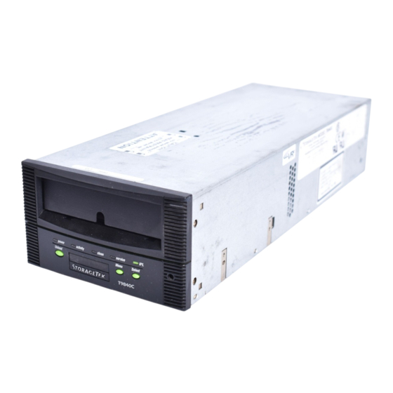
Page 16: Tape Drive
Where Encryption and SDP coexist, the Ethernet Port must be concurrently shared by using the Service Network. Note – Oracle neither supports nor assumes any responsibility for drive functional failures that occur during the unauthorized use of the drive’s maintenance port. -
Page 17: Interfaces
Encryption • StorageTek Virtual Operator Panel (VOP) customer or service versions provide support for the T9840D tape drive • Service Delivery Platform (SDP) • Service’s Tape Health Check Tool • StorageTek Diagnostic System (STDS) Starting with drive code 1.44.x04, you can use IPv6 addressing. An IPv6 address is a 128-bit value written as eight groups of four hexadecimal characters separated by colons (for example, 2001:0db8:85a3:0000:0000:8a2e:0370:7334). -
Page 18: Encryption Resources
For additional information on the encryption capabilities and features of the T10000 Tape Drive, see: • OKM 2.3 or higher • Oracle Key Manager, Administration Guide • Oracle Key Manager, Systems Assurance Guide • KMS 2.x • Crypto Key Management System, Administration Guide • Crypto Key Management System, Systems Assurance Guide •... -
Page 19: Table 1-1 Encryption Status Led State Descriptions
Encryption FIGURE 1-3 Encryption Status LED (SL8500 Library Drive Tray) The following table interprets the various states of the encryption status LED. Refer to the Crypto Key Management documentation for additional information. TABLE 1-1 Encryption Status LED State Descriptions LED State Mode Description Green... -
Page 20: Configurations
Configurations Configurations T9840 Tape Drives are available in desktop, rack-mountable, and library-attached configurations. Desktop and Rack-mountable Drive Units Both the desktop and rack-mount configurations, shown in FIGURE 1-4, feature manual tape cartridge loading. The desktop version (T9840A/B only) comprises a single drive and a power supply mounted within a cabinet with rubber feet. - Page 21 Configurations FIGURE 1-4 T9840 Desktop and Rack-mount Units FIGURE 1-5 CSL Desktop and Rack-mount (T9840A) Overview 21 December 2012...
- Page 22 Configurations FIGURE 1-6 T9840 Tape Drive Library Attached Configurations 22 T9840 URM December 2012...
-
Page 23: Cartridges
(9840C), or purple (T9840D). • The write-protect switch is yellow (9840A/B), green (9840C), or purple (T9840D). • A model-unique dimple pattern exists on the bottom of the cartridge case. To place orders electronically, send an e-mail to: tapemediaorders_ww@oracle.com Overview 23 December 2012... -
Page 24: Mixed Media Management
Mixed Media Management TABLE 1-2 Cartridge Read/Write Compatibility Drive Model Compatibility T9840A T9840B T9840C T9840D Read a cartridge formatted by: T9840A and T9840A and T9840A, T9840A, T9840B, T9840B T9840B T9840B, and T9840C, and T9840C T9840D Write or append data to a cartridge T9840A and T9840A and T9840C... -
Page 25: Media Information Region
Mixed Media Management Note – For additional information about mixed-media management, see “Cross-Density MIR Processing”. Media Information Region The T9840 tape drives use information recorded on each tape cartridge to access and manage that tape cartridge while it is loaded in the drive. This information is recorded at the beginning of the tape in an area known as the Media Information Region (MIR). -
Page 26: Cross-Density Mir Processing
Mixed Media Management When the tape cartridge is unloaded, as part of the unload routine, the memory- resident MIR information is written to the tape-resident MIR and the MIR invalid flag is turned off. A copy of the memory-resident MIR is stored in the drive’s persistent memory (EEPROM) and used should the MIR fail to be written because of a power failure or firmware problem (SNO or should not occur). - Page 27 Mixed Media Management • If a T9840C or T9840A/B written data cartridge has an invalid MIR, its contents cannot be read into the T9840D drive's memory and the user data pointer information will be unavailable. This causes a performance degradation. T9840C tape Drive Loaded With a T9840D Data Cartridge The T9840C drive will not be able to read the MIR written by a T9840D drive.
- Page 28 Mixed Media Management • Since a T9840C tape drive cannot correct nor rebuild a low-density data cartridge invalid MIR, the only options for increasing performance are: • Migrate the data to a high-density format cartridge, using a copy utility with a second T9840C drive. •...
-
Page 29: Exceptional Mir Processing
Mixed Media Management • If a T9840A/B drive has down level drive firmware, a high-density data cartridge would be considered as a blank tape cartridge. A low-density data cartridge would lose statistical data stored in the FIB during a previous mount into a T9840C drive. - Page 30 Mixed Media Management • If a tape cartridge with a partially valid MIR is mounted for long periods of time with locates to different locations, locate times will be inconsistent depending on whether the locate is to a record already in the rebuilt MIR, or if some low speed locate is required.
-
Page 31: Operator Controls
Operator Controls Several methods are available that enable you to determine the state of the tape drive, perform operator tasks, or view and alter drive configuration settings. All T9840 drives have a physical operator panel. You can use this panel to access the drive menu system, to view drive indicators, to access front panel switches, and to load a tape cartridge. -
Page 32: Load/Unload Slot
Front Panel FIGURE 2-1 T9840 Operator Panel Load/Unload Slot The load/unload slot is the opening in the front panel that accepts 9840 Tape Cartridges that you load by hand, that a T9840A CSL loads, or that a library robotic hand loads. After a tape cartridge is inserted, the loader mechanism raises to engage the tape cartridge and draw it into the loaded position. -
Page 33: Indicators
Front Panel Indicators TABLE 2-1 describes T9840 Tape Drive operator panel indicators. TABLE 2-1 Operator Panel Indicators Indicator Indication Explanation power (green) Off: Power is not applied. Flashing: Unit is powering up, performing IPL, or collecting dump data. Flashing does not stop: IPL failed. On (steady): Power applied and IPL complete. -
Page 34: Switches
Front Panel Switches TABLE 2-2 describes T9840 operator panel switch functions. TABLE 2-2 Operator Panel Switches Switch Description Menu Pressing the Menu switch accesses the menu system, steps through a series of submenus, or answers No to a displayed question. Pressing the Menu switch the first time causes the Online/Offline selection to display. - Page 35 Front Panel such as an asterisk (*). When the tape bar is not activated, the lighted segments and dots form text messages. The text messages may display steadily, flashing, or alternating with other messages. FIGURE 2-2 Tape Bar Tape Bar The tape bar uses the operator panel display to show the amount of tape that has been written and read.
-
Page 36: Virtual Operator Panel
Virtual Operator Panel Read Bar As data is read from the tape, the read bar appears in the center of the write bar as a single row of unlighted dots. This row is bordered above and below by single rows of lighted dots. -
Page 37: Library Controls/Indicators
Library Controls/Indicators Library Controls/Indicators When a T9840 Tape Drive is attached to the SL3000 or SL8500 Modular Library System, you cannot access the drive operator panel on the front of the drive without opening the library door. The drive tray rear panel does provide some indicators and an Ethernet port. -
Page 38: Storagetek Library Console
Library Controls/Indicators StorageTek Library Console Although you cannot access the T9840 Tape Drive Operator Panel to view menu items, you can use the StorageTek Library Console (SLC), local or remote, to display data pertinent to the attached drives. Note – General guidance on using the SLC application is available within the SLC “Help”... -
Page 39: Drive Specific Displays
Library Controls/Indicators Drive Specific Displays When you select an individual drive in the tree pane, the right pane changes to display drive-specific data instead of the drive folder summary data. You can view and use the SLC drive displays to develop reports to assist with the analysis of drive-related problems. - Page 40 Library Controls/Indicators Properties The General block in the Properties tab, FIGURE 2-7, displays some of the data from the drive folder summary plus the drive interface type (not displayed in the summary). The Drive Configuration block displays selected configuration items, such as World- Wide-Name (this is a dynamic value, dWWN, that is auto-set by the library relative to the drive bay number).
- Page 41 Library Controls/Indicators Display The Display tab, FIGURE 2-8, contains three sections: Network Data, Drive Virtual Op Panel, and Drive LED Status. FIGURE 2-8 SL8500 SLC Drive Display Tab Operator Controls 41 December 2012...
- Page 42 Library Controls/Indicators 42 T9840 URM December 2012...
-
Page 43: Menus
Menus The menu system provides the operator and service representative a means to determine drive configuration settings, access drive utilities, and display the drive firmware level at the drive operator panel. The menu system consists of information or values, submenus, and options that appear in the display section of the operator panel (see “Display”... - Page 44 Menu Structure Overview • Press Menu (No) to bypass and advance to the next menu. • Press Select (Yes) to enter the submenus. When you press the Menu switch on the operator panel, the first menu provides selection of Online (default) or Offline menus. •...
-
Page 45: Online Menu Operation
Online Menu Operation Online Menu Operation When the drive is Online, the menus shown in FIGURE 3-2 on page 46 are available. Note – Individual submenu items in the illustration are based 1on the T9840A/B/C drives using a code level lower than 1.42.x07. The content of the figure was created before the T9840D tape drive was available. - Page 46 Online Menu Operation FIGURE 3-2 Online Menus 46 T9840 URM December 2012...
- Page 47 Online Menu Operation Fibre Channel View Configuration Menu Tree (T9840A/B/C) Use the online view configuration menu tree as a brief guide. Online/Offline [Press Select to toggle; then press Menu to set.] Port X YYY {A/B and ENA/DIS} View CFG ? (View Configuration) {Press Select to enter, press Menu to bypass.] Cmprss xxx {Yes/Off/No} (compression mode) Full DSE x {Y/N} (data security erase mode) SL Prot x {Y/N} (standard label protection mode)
- Page 48 Online Menu Operation Fibre Channel View Configuration Menu Tree (T9840D) Use the online view configuration menu tree as a brief guide. Online/Offline [Press Select to toggle; then press Menu to set.] View CFG ? (View Configuration) [Press Select to enter or press Menu to bypass.] Intf XXXXX {FICON/FCP} View PrtA? (view current port attributes) A=xxxxxxay (24-bit address ID - when port login is complete)
-
Page 49: Scsi View Configuration Menu Tree
Online Menu Operation SCSI View Configuration Menu Tree Use the online view configuration menu tree as a brief guide. Online/Offline [Press Select to toggle; then press Menu to set.] View CFG? (View Configuration) [Press Select to enter or press Menu to bypass.] Cmprss xxx {Yes/Off/No} (compression mode) Full DSE x {Y/N} (data security erase mode) SL Prot x (Y/N) (standard label protection mode) -
Page 50: Escon View Configuration Menu Tree
Online Menu Operation ESCON View Configuration Menu Tree Use the online view configuration menu tree as a brief guide. Online/Offline [Press Select to toggle; then press Menu to set.] Port xxx {ENA/DIS} (enables or disables the ESCON port) View CFG? (View Configuration) [Press Select to enter or press Menu to bypass.] Cmprss Xxx {Yes/Off/No} (compression mode) Full DSE X {Y/N} (data security erase mode) Drv Adr xy (2-character hexidecimal logical drive address - usually 00) - Page 51 Online Menu Operation FICON View Configuration Menu Tree (T9840B/C) Use the online view configuration menu tree as a brief guide. Online/Offline [Press Select to toggle; then press Menu to set.] View CFG ? (View Configuration) [Press Select to enter or press Menu to bypass.] Intf FICON View PrtA? (view current port attributes) A=xxxxxxay (24-bit address identifier, connection type, and port speed - when port log in is...
- Page 52 Online Menu Operation H=xxxxxxxx (first half, 64-bit drive node world-wide-name) L=xxxxxxxx (second half, 64-bit drive node world-wide-name) WWN Custom (only when custom/dynamic WWN is set) S/N=xxxxxx (drive serial number) (last six-characters of drive DMOD) Exit CFG ? (exit view configuration) [Press Select to exit or press Menu to return to the View CFG? submenu.] 52 T9840 URM December 2012...
- Page 53 Online Menu Operation FICON View Configuration Menu Tree (T9840D) Use the online view configuration menu tree as a brief guide. Online/Offline [Press Select to toggle; then press Menu to set.] View CFG ? (View Configuration) [Press Select to enter or press Menu to bypass.] Intf XXXXX {FICON/FCP} View PrtA? (view current port attributes) A=xxxxxxay (24-bit address identifier, connection type, and port speed - when...
- Page 54 Online Menu Operation H=xxxxxxxx (first half, 64-bit drive node world-wide-name) L=xxxxxxxx (second half, 64-bit drive node world-wide-name) WWN Custom (only when custom/dynamic WWN is set) S/N=xxxxxx (drive serial number) (last six-characters of drive DMOD) Exit CFG ? (exit view configuration) [Press Select to exit or press Menu to return to the View CFG? submenu.] TCP/IP View Configuration Menu Use the following menu tree as a brief guide to view the TCP/IP settings of the...
-
Page 55: Offline Menus
Offline Menus Offline Menus With the offline menus, the operator can change configuration settings, reformat a data tape cartridge and build the media information region (MIR) on a tape cartridge. FIGURE 3-3 Offline Menus/Interface Menu Tree Menus 55 December 2012... -
Page 56: Configuration Changes
Offline Menus Configuration Changes You can change configuration settings from the drive offline menu system by using the Menu and Select switches to navigate the offline menu system. You enter the configuration or TCP/IP submenu when you press the Select switch while the main menu item appears in the display. -
Page 57: Drive Operations Menu
Offline Menus Drive Operations Menu The Drv Menu ? branch of the main menu is the same for Fibre Channel, SCSI, ESCON, and FICON interfaces. FIGURE 3-4 shows an expansion of the drive operations sub-menus. Note that the menu items both preceding and following the Drv Menu ? branch vary with the type of data path interface (see FIGURE 3-3 on page 55 for specific menu... - Page 58 Offline Menus 58 T9840 URM December 2012...
-
Page 59: Operator Tasks
Operator Tasks This chapter discusses operator tasks primarily for desktop and rack-mounted tape drives. Most of these tasks rely on the physical operator panel switches, alphanumeric display, and the drive menu system. Note – For operator tasks relating to drives within a library, consult the appropriate library operator guide. -
Page 60: Power-Off A Drive
Basic Tasks ▼ Power-off a Drive To remove power from the desktop and rack-mount configuration: 1. Make sure the tape drive is not in use. Check for the following elements: a. There are no active jobs, applications, or programs using this drive. b. -
Page 61: Cartridge Procedures
Cartridge Procedures Cartridge Procedures • “Write-protect/Enable a Data Cartridge” on page 61 • “Load a Data Cartridge” on page 62 • “Unload a Data Cartridge” on page 63 • “Use a Cleaning Cartridge” on page 63 Cartridge Handling Precautions Magnetic fields are present near disk drives and electric motors (the larger the electric motor, the stronger the magnetic field is which surrounds it). -
Page 62: Load A Data Cartridge
Cartridge Procedures The switch points to a padlock symbol on the case to indicate a status: Locked: Write protected. Data can only be read from the data cartridge. Unlocked: Write enabled (unprotected). Data can be read from and written to the standard data cartridge. -
Page 63: Unload A Data Cartridge
Cartridge Procedures ▼ Unload a Data Cartridge Caution – Possible data loss: Do not push the Unload switch while a data cartridge is in use. To remove cartridges from the drive: 1. Make sure the tape drive is not in use. Check for the following elements: a. -
Page 64: Menu System Tasks
• “Exit the Menu System” on page 69 You can use the Virtual Operator Panel, version 1.0.12 (or higher), with Oracle’s StorageTek T9840D tape drive to perform many of the operator tasks listed above (see “Virtual Operator Panel” on page 36). -
Page 65: Place The Drive Online
Menu System Tasks ▼ Place the Drive Online To change the tape drive state from offline to online: 1. Press the operator panel Menu switch until Offline appears in the display window. Note – If you are within a submenu, press the Menu switch until Exit XXX ? appears in the display window and press the Select switch to enter the main menu. -
Page 66: View The Firmware Release Level
Menu System Tasks 5. Press either the Menu or Select switch until Exit CFG ? appears in the display window. 6. Press either the Select switch (Yes) to exit the submenu or the Menu switch (No) to repeat the view configuration sequence. 7. -
Page 67: Reformat A Cartridge
Menu System Tasks 2. Press the operator panel Menu switch. Online appears in the display window. 3. Press the operator panel Select switch to toggle the drive state. Offline appears in the display window to indicate a successful transition to the offline state. -
Page 68: Build The Mir
Menu System Tasks 12. Press either the Select switch to exit the menu system or the Menu switch to repeat the Online/Offline selection. Note – It is a best practice to return the drive to the online state. “Place the Drive Online” on page ▼... -
Page 69: Exit The Menu System
Menu System Tasks ▼ Exit the Menu System 1. Press the Menu switch repeatedly until Exit Menu? appears in the display window. Note – If you are within a submenu, press the Menu switch until Exit XXX ? appears in the display window and press the Select switch to enter the main menu. - Page 70 Menu System Tasks 70 T9840 URM December 2012...
-
Page 71: Indicators And Messages
Indicators and Messages This chapter summarizes the operator panel indicator lights and display messages. Indicators TABLE 5-1 shows the meaning of the indicators located on the front panel and the recommended action. TABLE 5-1 Operator Panel Indicators Indicator Meaning Recommended Action power activity clean... -
Page 72: Messages
Messages Messages TABLE 5-2 lists operator panel display messages, meanings, and recommended actions. TABLE 5-2 Operator Panel Display Messages Display Meaning Recommended Action * (asterisk) The tape drive is online but a cartridge tape Load a cartridge tape as required. is not loaded. - Page 73 Messages TABLE 5-2 Operator Panel Display Messages (Continued) Display Meaning Recommended Action CodUpFail1 The tape drive cannot read the data cartridge Try another cartridge tape. tape, or the tape drive cannot position the data cartridge tape. CodUpFail2 The EEPROM failed. Contact authorized service personnel.
- Page 74 Messages TABLE 5-2 Operator Panel Display Messages (Continued) Display Meaning Recommended Action Init xxxx. An initialization error occurred. Contact authorized service where xxxx is personnel. an FSC IPL Pend The IPL switch has been pressed. None LOAD CC The common controller code is loading; IPL None is proceeding.
- Page 75 Messages TABLE 5-2 Operator Panel Display Messages (Continued) Display Meaning Recommended Action Ready A The loaded cartridge tape is a VolSafe None cartridge. Ready F The loaded cartridge tape is write-protected. None Ready H A loaded high-density data cartridge is write- Reload with low-density cartridge or enabled by the cartridge write-protect switch intentionally over-write from BOT.
-
Page 76: Potential Operator Recovery Scenarios
Messages Potential Operator Recovery Scenarios The following table contains Fault Symptom Codes (FSCs) that commonly result from an operator error. The first column in the table lists an operator panel message at the time of the error event. The description column provides insight into the error condition from which you should be able to determine a recovery action. -
Page 77: Translated Messages
Messages Translated Messages TABLE 5-4 lists operator panel display messages that are translated when the drive configuration Language option is set to something other than English. TABLE 5-4 Translated Display Messages English Espanol Francais Italiano Deutsch *CLEANING* *LIMPIEZA* *NETTOYAGE *PULIZIA* *REINIGEN* CHK XXXX ERR XXXX... - Page 78 Messages 78 T9840 URM December 2012...
-
Page 79: Specifications
Specifications This appendix lists the physical, power, and performance specifications for the T9840 tape drive plus the environmental requirements for the drive and data cartridges. Physical Specifications This section lists the physical specifications for T9840 tape drives in three configurations: desktop, rack mount, and library attached. Tape Drive Only TABLE A-1 lists the T9840 tape drive physical specifications. -
Page 80: Rack-Mount Configuration
Physical Specifications Rack-Mount Configuration Chassis dimensions: 483 mm (19 in.) wide 177 mm (7.0 in.) high 630 mm (24.8 in.) deep plus 76 mm (3 in.) for cables Weight: Single drive 14.1 kg (32 lb), dual drive 20.4 kg (45 lb), and Cartridge Scratch Loader 18 kg (39 lb) Library-attached Configuration TABLE A-3... -
Page 81: Power Specifications
Power Specifications Power Specifications The power specifications for the T9840 tape drive are listed in the following table. TABLE A-4 T9840 Tape Drive Power Specifications Characteristic Value Input voltage 100 to 240 VAC Input frequency 50 to 60 Hz Power consumption T9840D 61.7 W - write 43 W - Idle with tape loaded... -
Page 82: Table A-5 T9840 Drive And Power Supply Environmental Requirements
Environmental Requirements TABLE A-5 T9840 Drive and Power Supply Environmental Requirements Description Range Temperature Operating 15° to 32°C (59° to 90°F) Shipping -40° to 60°C (-40° to 140°F) Storing 10° to 40°C (50° to 104°F) Relative Humidity, (non-condensing) Operating 20% to 80% Shipping 10% to 95% Storing... -
Page 83: Tape Cartridge
Performance Specifications Tape Cartridge TABLE A-6 lists the T9840 tape cartridge environmental requirements. TABLE A-6 T9840 Tape Cartridge Environmental Requirements Characteristic Value Temperature Operating 15° to 32°C (59° to 90°F) Storage (up to four weeks) 5° to 32°C (41° to 90°F) Storage (archival) 18°... -
Page 84: Table A-7 T9840 Tape Drive Performance Specifications
Performance Specifications TABLE A-7 T9840 Tape Drive Performance Specifications Value Characteristic T9840A T9840B T9840C T9840D Capacity and Performance Capacity, native 20 GB 20 GB 40 GB 75 GB Data buffer size 8 MB 32 MB 64 MB 64 MB tape speed, read/write 2 m/s 4 m/s 3.295 m/s... -
Page 85: Tape Cartridge
Performance Specifications Tape Cartridge TABLE A-8 lists the physical and performance specifications for the StorageTek 9840 data cartridge. The cleaning cartridges have the same physical specifications. TABLE A-8 StorageTek 9840 Data Cartridge Physical and Performance Specifications Characteristic Value Cartridge physical data Drive compatibility T9840A, T9840B, T9840C, T9840D Form factor... -
Page 86: T9840 Urm December
Performance Specifications 86 T9840 URM December 2012... -
Page 87: Cartridge Care
Cartridge Care StorageTek 9840 tape cartridges require care to ensure proper operation and longevity. ▼ To Handle a Tape Cartridge Caution – Tape cartridge damage or data loss: Handle tape cartridges properly. • Follow accepted tape cartridge handling practices. Consider the following guidelines: •... -
Page 88: To Identify A Damaged Cartridge
▼ To Identify a Damaged Cartridge Caution – Equipment damage: Do not load a damaged cartridge. • Inspect the cartridge for problems before loading it into a drive. Look for the following problems: • A cracked or broken case • A dirty case (see “To Clean a Cartridge”) •... -
Page 89: Controlling Contaminants
• Severity level G1 per ANSI/ISA 71.04-1985. Oracle currently requires the ISO 14644-1 standard approved in 1999, but will require any updated standards for ISO 14644-1 as they are approved by the ISO governing body. The ISO 14644-1 standard primarily focuses on the quantity and size of particulates as well as the proper measurement methodology, but does not address the overall mass of the particulates. -
Page 90: Contaminant Properties And Sources
Contaminant Properties and Sources numbers, and can easily circumvent many sensitive components’ internal air filtration systems. When computer hardware is exposed to these submicron particles in great numbers they endanger system reliability by posing a threat to moving parts, sensitive contacts and component corrosion. Excessive concentrations of certain gasses can also accelerate corrosion and cause failure in electronic components. -
Page 91: Operator Activity
Contaminant Properties and Sources Submicron particulates are much more dangerous to sensitive computer hardware, because they remain airborne for a much longer period of time, and they are more apt to bypass filters. Operator Activity Human movement within the computer space is probably the single greatest source of contamination in an otherwise clean computer room. -
Page 92: Cleaning Activity
Contaminant Effects Cleaning Activity Inappropriate cleaning practices can also degrade the environment. Many chemicals used in normal or “office” cleaning applications can damage sensitive computer equipment. Potentially hazardous chemicals outlined in the “Cleaning Procedures and Equipment” section should be avoided. Out-gassing from these products or direct contact with hardware components can cause failure. -
Page 93: Shorts
Room Conditions Shorts Conductive pathways can arise through the accumulation of particles on circuit boards or other components. Many types of particulate are not inherently conductive, but can absorb significant quantities of water in high-moisture environments. Problems caused by electrically conductive particles can range from intermittent malfunctioning to actual damage to components and operational failures. -
Page 94: Exposure Points
Exposure Points Unsealed concrete, masonry or other similar materials are subject to continued degradation. The sealants and hardeners normally used during construction are often designed to protect the deck against heavy traffic, or to prepare the deck for the application of flooring materials, and are not meant for the interior surfaces of a supply air plenum. -
Page 95: Filtration
Filtration • Automatic doors should be avoided in areas where they can be accidentally triggered. An alternate means of control would be to remotely locate a door trigger so that personnel pushing carts can open the doors easily. In highly sensitive areas, or where the data center is exposed to undesirable conditions, it may be advisable to design and install personnel traps. -
Page 96: Positive Pressurization And Ventilation
Positive Pressurization and Ventilation Low efficiency filters are almost totally ineffective at removing sub-micron particulates from the air. It is also important that the filters used are properly sized for the air handlers. Gaps around the filter panels can allow air to bypass the filter as it passes through the air conditioner. -
Page 97: Daily Tasks
Cleaning Procedures and Equipment overall commitment to excellence and quality. An effective cleaning schedule must consist of specially designed short-term and long-term actions. These can be summarized as follows: Frequency Task Daily Actions Rubbish removal Weekly Actions Access floor maintenance (vacuum and damp mop) Quarterly Actions Hardware decontamination Room surface decontamination... -
Page 98: Quarterly Tasks
Cleaning Procedures and Equipment Quarterly Tasks The quarterly statement of work involves a much more detailed and comprehensive decontamination schedule and should only be conducted by experienced computer room contamination-control professionals. These actions should be performed three to four times per year, based on the levels of activity and contamination present. All room surfaces should be thoroughly decontaminated including cupboards, ledges, racks, shelves and support equipment. -
Page 99: Activity And Processes
Activity and Processes work and cleaned with a damp sponge as well. Any unusual conditions, such as damaged floor suspension, floor tiles, cables and surfaces, within the floor void should be noted and reported. Activity and Processes Isolation of the data center is an integral factor in maintaining appropriate conditions. - Page 100 Activity and Processes 100 T9840 URM December 2012...
-
Page 101: Glossary
Glossary This glossary defines terms and abbreviations in this publication. Some of the definitions are taken from other glossaries. The letters in the parentheses that follow some definitions indicate the source of the definition: (A) The American National Standard Dictionary for Information Systems, ANSI X3.172- 1990, copyright 1990 by the American National Standards Institute (ANSI). - Page 102 block A collection of contiguous records recorded as a unit. Interblock gaps separate blocks, and each block can contain one or more records. buffer A routine or storage that compensates for a difference in the rate of data flow, or the time of occurrence of events when transferring data from one device to another.
- Page 103 data error rate The number of errors that occur per a measurable amount of data on a tape. data rate The speed of a data transfer process, usually expressed in bits per second or bytes per second. (IBM) Data Security Erase (DSE) A random binary pattern, over-writing existing data, from the point of an “Erase”...
- Page 104 environmental requirement Any of the physical conditions required for the protection and proper operation of a functional unit; the requirement is usually specified as a nominal value and a tolerance range. For a device, there may be more than one set of environmental requirements;...
- Page 105 FICON channel A channel having a Fibre Channel connection (FICON) channel-to-control-unit I/O interface that uses optical cables as a transmission medium. May operate in either FC or FCV mode. file-protect To prevent the erasure or overwriting of data stored on data cartridges. See also write- protect switch.
- Page 106 Initial Program Load (IPL) The initialization procedure that causes an operating system to commence operation. initialization The operations required for setting a device to a starting state, before the use of a data medium, or before implementation of a process. (T) input/output (I/O) Pertaining to a device, process, or channel involved in data input, data output, or both.
- Page 107 Multiple Virtual Storage (MVS) IBM's Multiple Virtual Storage, consisting of MVS/System Product Version 1 and the MVS/370 Data Facility Product operating on a System/370 processor. (IBM). Multiple Virtual Storage/Enterprise Systems Architecture (MVS/ESA) An extended version of IBM's MVS. See Multiple Virtual Storage MVS/ESA See Multiple Virtual Storage/Enterprise Systems Architecture network...
- Page 108 reclaim The act of overwriting a 9840 legacy data cartridge by a newer generation drive. For example, a cartridge written by a T9840A drive can be overwritten (reclaimed) by either a T9840C or T9840D drive while a cartridge written by a T9840C drive can be reclaimed by a T9840D drive.
- Page 109 transmission control protocol/internet protocol (TCP/IP) A set of communication protocols that support peer-to-peer connectivity functions for both local and wide area networks. (IBM) vary offline To change the status of a device from online to offline. When a device is offline, no data set may be opened on that device.
- Page 110 110 T9840 URM December 2012...
-
Page 111: Index
Index Symbols VolSafe 23 write protect 61 * (asterisk) message 72 cartridge scratch loader, description 20 CC Diags message 72 Chk xxxx message 72 clean indicator 33 activity indicator 33 clean the drive 63 address cleaning HLI-PRC 38 cartridge overview 23 IP address, SLC 38 data center 96 IPv6 17, 36, 64... - Page 112 DmpWrFail2 message 73 drive configurations handling cartridges 87 cartridge scratch loader 20 HLI-PRC address 38 library attached 20 manual load drive 20 environmental requirements 82 indicator front panel 31 activity 33 indicators 33 clean 33 interfaces 17 encryption status 18 load/unload slot 32 operator panel 31 maintenance port 16...
- Page 113 management of mixed media 24 OnLn Pend 74 manual load drive, description 20 operator panel display 72 manual unload device 33 operator panel display, translated 77 media, cartridge management 24 Power Fail 74 Memory Err message 74 Reading 74 menu Ready A 75 operations Ready F 75...
- Page 114 67 store a data cartridge 87 power-off the drive 60 structure of menus 43 power-on the drive 59 support, Oracle 11 set the drive offline 66 switches, operator panel 34 set the drive online 65 unload data cartridge 63...
Need help?
Do you have a question about the StorageTek T9840 and is the answer not in the manual?
Questions and answers