Table of Contents
Advertisement
Quick Links
Download this manual
See also:
Operator's Manual
Advertisement
Chapters
Table of Contents

Related Manuals for Oracle StorageTek T10000


Summary of Contents for Oracle StorageTek T10000
- Page 1 StorageTek T10000 Tape Drive Fibre Channel Interface Reference Manual Part Number: E20425-06 August 2016 Submit comments about this document to STP_FEEDBACK_US@ORACLE.COM.
- Page 2 Oracle Corporation and its affiliates disclaim any liability for any damages caused by use of this software or hardware in dangerous applications.
-
Page 3: Table Of Contents
Table of Contents Figures ............................9 List of Tables .......................... 11 Preface ............................15 Access to Oracle Support ......................15 What’s New ..........................17 General Information ......................19 Overview ..........................20 Tape Drive Description ......................22 Specifications ........................... 25 Operations .......................... - Page 4 Control Byte ........................42 Erase Command ........................43 Generate Recommended Access Order Command ..............44 Format Medium Command...................... 47 Inquiry Command ........................48 Inquiry Data Format ......................49 Vital Product Data Pages ..................... 52 Load Display Command ......................57 Load Display Data Format ....................57 Load/Unload Command ......................
- Page 5 Read/Write Error Recovery Page ..................115 Disconnect–Reconnect Page ....................116 Control Data Protection Mode Page .................. 117 Data Compression Page ....................120 Device Configuration Page ....................121 Device Configuration Extension Mode Page ..............123 Fibre Channel Logical Unit Control Page ................124 Fibre Channel Port Control Page ..................
- Page 6 Receive Recommended Access Order Command..............167 Release Unit Command......................170 Report Density Support Command ..................171 Report Density Support Data .................... 172 Density Support Block Descriptor ..................173 Report LUNs Command ......................176 Report LUNs Parameter Data .................... 176 Report Supported Operation Codes Command ..............177 All_Commands Parameter Data Format ................
- Page 7 Build Instructions ......................256 Main Function and Defines ....................256 Software Method ......................259 Hardware Assist ....................... 262 Media Validation ........................267 Media Validation Overview ....................267 SCSI Verify Command (16 Byte)..................... 268 SCSI Verify Command Table: Verify Options ..............270 SCSI Verify Command Table: Other Functions ..............
- Page 8 8 T10000: Interface Reference Manual August 2016...
-
Page 9: Figures
Figures FIGURE 1-1 T10000A and T10000B Tape Drive Rear View ............. 23 FIGURE 1-2 T10000C Tape Drive Rear View .................. 23 FIGURE 1-3 T10000D Tape Drive Rear View .................. 24 SB-2 CRC Program Example ..................250 FIGURE A-1 August 2016 Figures 9... - Page 10 10 T10000: Interface Reference Manual August 2016...
-
Page 11: List Of Tables
List of Tables TABLE 1-1 Fibre Channel Reference Documentation ..............19 TABLE 1-2 Fibre Channel Layers ....................21 T10000A and T10000B Tape Drive Performance Specifications........25 TABLE 1-3 TABLE 1-4 T10000C Tape Drive Performance Specifications............26 TABLE 1-5 T10000D Tape Drive Performance Specifications ............27 TABLE 2-1 Addressing Scheme.................... - Page 12 TABLE 3-36 Non-Medium Error Page Codes ................. 71 TABLE 3-37 Sequential Access Device Page Codes................. 72 TABLE 3-38 TapeAlert Flags......................73 TABLE 3-39 Tape Capacity Page Codes ..................76 TABLE 3-40 T10000A and T10000B Vendor Drive Statistics Page Codes ......... 77 TABLE 3-41 Vendor Port Statistics Page Codes ................
- Page 13 TABLE 3-90 Persistent Reserve Out Command ................136 TABLE 3-91 Persistent Reserve Out Parameter List ..............137 TABLE 3-92 Prevent/Allow Medium Removal Command ............140 TABLE 3-93 Read Command ....................... 141 TABLE 3-94 Read T10 PI (16) Command ..................144 TABLE 3-95 Read Attribute Command ..................
- Page 14 TABLE 3-144 Field Pointer Sense Key Illegal Request Specific Data..........191 TABLE 3-145 Progress Indication Sense Key Not Ready or No Sense Specific Data ......192 TABLE 3-146 Sense Key Code Descriptions ................... 193 TABLE 3-147 Sense Key with ASC and ASCQ................194 TABLE 3-148 Data Returned for Request Sense Command.............
-
Page 15: Preface
• 4FC = T10000A or T10000B or T10000C with a 4 Gb interface • 16FC = T10000D • T10000A or T10000B or T10000C or T10000D • FC = Fibre Channel Access to Oracle Support Oracle customers have access to electronic support through My Oracle Support. For information, visit http://www.oracle.com/support/contact.html or visit http:// www.oracle.com/accessibility/support.html... - Page 16 Access to Oracle Support 16 T10000: Interface Reference Manual August 2016...
-
Page 17: What's New
What’s New Information added about the T10000D tape drive. Information added about the T10000D tape drive support of the T10 Protection Information feature. August 2016 What’s New 17... - Page 18 18 T10000: Interface Reference Manual August 2016...
-
Page 19: General Information
General Information This chapter contains an overview about the Fibre Channel specifications for Oracle’s StorageTek T10000 Tape Drive, which conforms to the: • American National Standards Institute (ANSI) • National Committee for Information Technology Standards (NCITS) TABLE 1-1 lists the documents that help define this implementation. -
Page 20: Overview
Overview TABLE 1-1 Fibre Channel Reference Documentation (Continued) Specification Revision SCSI Fibre Channel Protocol 2 ANSI NCITS:350:2003 SCSI Fibre Channel Protocol 3 ANSI INCITS:416:2006 SCSI–3 Architecture Model (SAM-2) ANSI NCITS:366:2003 SCSI-3 Architecture Model (SAM-3) ANSI INCITS:402:2005 SCSI–3 Primary Commands (SPC–2) ANSI NCITS:351:2001 SCSI-3 Primary Commands (SPC-3) ANSI NCITS:408:2005... -
Page 21: Table 1-2 Fibre Channel Layers
Overview TABLE 1-2 for a description of the Fibre Channel layers. TABLE 1-2 Fibre Channel Layers ULPs SCSI SBCCS HIPPI FC-4 • Upper Level Protocol Mapping • Mapping of ULP functions and constructs FC-3 Common Services FC-2 Link Service • Login and Logout services •... -
Page 22: Tape Drive Description
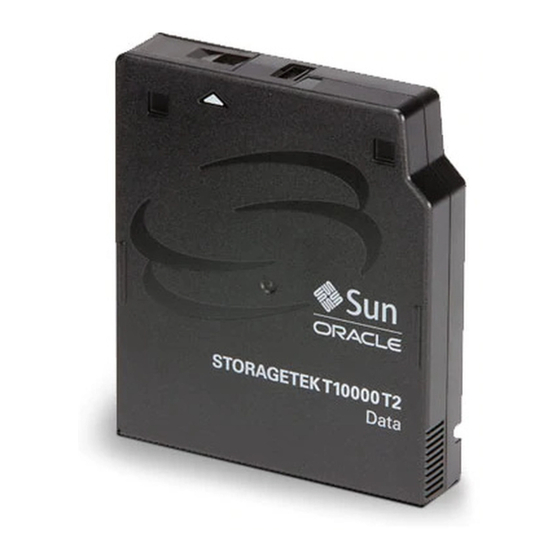
Tape Drive Description Tape Drive Description Size: The T10000 tape drive is a small, modular, high-performance tape drive designed for high-capacity storage of data. The drive is: • Height = 8.89 cm (3.5 in.) • Width = 14.6 cm (5.75 in.) •... - Page 23 Tape Drive Description FIGURE 1-1 T10000A and T10000B Tape Drive Rear View 1. Drive status LED 5. Ethernet port 2. Recessed switch (service only) 6. Encryption status LED 3. Tape transport interface (TTI) connector 7. Power supply connector 4. Fibre Channel, LC interface ports (2) A & B FIGURE 1-2 T10000C Tape Drive Rear View 1.
- Page 24 Tape Drive Description FIGURE 1-3 T10000D Tape Drive Rear View 1. Tape transport interface (TTI) connector 4. Fibre Channel, LC interface ports (2) A & B 2. Recessed switch (service only) 5. RJ-45 Ethernet connector 3. Power supply connector 24 T10000: Interface Reference Manual August 2016...
-
Page 25: Specifications
Specifications Specifications This section lists the physical, environmental, and performance specifications for the T10000 tape drive. TABLE 1-3 T10000A and T10000B Tape Drive Performance Specifications Characteristic Specification Capacity and Performance T10000A Capacity, native 500 GB (5 x 10 bytes) T10000A Sport Cartridge, native 120 GB T10000B Capacity, native 1 TB (1 x 10... -
Page 26: Table 1-4 T10000C Tape Drive Performance Specifications
Specifications TABLE 1-4 T10000C Tape Drive Performance Specifications Characteristic Specification Capacity and Performance T10000C Capacity, native 5 TB (5 X 10 bytes) T10000C Sport Cartridge, native 1 TB Data buffer size 2 GB Tape speeds: Read and write 3.7 and 5.6 m/s File search and locates 13 m/s High speed rewind... -
Page 27: Table 1-5 T10000D Tape Drive Performance Specifications
Specifications TABLE 1-5 T10000D Tape Drive Performance Specifications Characteristic Specification Capacity and Performance T10000D Capacity, native 8 TB (8 X 10 bytes) T10000D Sport Cartridge, native 1.6 TB Data buffer size 2 GB Tape speeds: Read and write 2.75, 3.25, 3.75, 4.25, 4.75 m/s File search and locates 13 m/s High speed rewind... - Page 28 Specifications 28 T10000: Interface Reference Manual August 2016...
-
Page 29: Operations
Operations This chapter describes how StorageTek tape drives operate using a Fibre Channel (FC) interface. Note – This document is defined by the requirements in FC-Tape Revision 1.17. As updates occur to the FC-Tape document, this document will be updated accordingly. Connections The T10000 tape drives support various connections: •... -
Page 30: Direct N_Port Attachment
Direct N_Port Attachment Direct N_Port Attachment The T10000 tape drives support direct attachment to a host through a host bus adapter (HBA) that creates an N-Port. The HBA sends and receives to and from the tape drive. Addressing StorageTek tape drives use: Port name, Node name, and Port ID for login validation. The StorageTek registration ID is 24 bits consisting of: •... -
Page 31: Scsi Features
SCSI Features SCSI Features The following sections describe the SCSI features supported by the tape drives. Auto Contingent Allegiance StorageTek tape drives do not support Auto Contingent Allegiance (ACA). Asynchronous Event Notification StorageTek tape drives do not support asynchronous event notification (AEN). Command Linking StorageTek tape drives do not support Command Linking. -
Page 32: Busy
Status Byte Busy Busy (08) status occurs when the target: • Is busy performing another operation • Cannot accept a command The normal initiator recovery from a Busy status is to reissue the command. Check Condition Check Condition (02) status occurs when any error, unit exception, or abnormal condition that generates sense data occurs. -
Page 33: Device Reservations
Device Reservations Device Reservations The T10000 tape drives support the Reserve/Release management method and also the Persistent Reservations management method. These methods are defined in the ANSI SCSI-3 Primary Commands (SPC-2) standard. • See TABLE 2-2 for the reservation restrictions placed on commands for the Reserve/Release management method. - Page 34 Device Reservations TABLE 2-2 Reserve/Release Management Method (Continued) Command Action when Reserved by a different Initiator Release Unit (17h/57h) Allowed, the reservation is not released. Report Density Support (44h) Allowed Report LUNs (A0h) Allowed Report Supported Operations Codes (A3h–0Ch) Conflict Report Supported Task Management Conflict Functions (A3h–0Dh)
-
Page 35: Table 2-3 Persistent Reservation Management Method
Device Reservations TABLE 2-3 lists the reservation restrictions placed on the Persistent Reservations management method. TABLE 2-3 Persistent Reservation Management Method Command From Non-registered Initiators From Registered Initiators Erase (19h) Conflict Allowed Inquiry (12h) Allowed Allowed Load Display (06h) Conflict Allowed Load/Unload (1Bh) Conflict... - Page 36 Device Reservations TABLE 2-3 Persistent Reservation Management Method (Continued) Command From Non-registered Initiators From Registered Initiators Report Target Port Groups Allowed Allowed (A3h–0Ah) Request Sense (03h) Allowed Allowed Reserve Unit (16h/56h) Conflict Allowed, reservation is not changed Rewind (01h) Conflict Allowed Send Diagnostic (1Dh) Conflict...
-
Page 37: Commands
Commands This chapter defines the SCSI-3 commands for the StorageTek T10000 Tape Drive with a Fibre Channel interface. Overview StorageTek uses the SCSI-3 command set to transfer commands and data over Fibre Channel. The following describes how StorageTek implements these SCSI commands: •... - Page 38 Commands TABLE 3-1 Supported SCSI Commands (Continued) Command Code Reference Page Format Medium SSC-3 Log Sense SPC-2 Mode Select 15h / 55h SPC-2 Mode Sense 1Ah / 5Ah SPC-2 Persistent Reserve In SPC-2 Persistent Reserve Out SPC-2 Prevent/Allow Media Removal Read Read T10 PI SSC-5...
-
Page 39: Implementation Requirements
Implementation Requirements Implementation Requirements The initiator sends commands to the target using Command Descriptor Blocks (CDBs). The CDBs contain a format that includes: • Operation code • Command parameters • Control byte For some commands, a list of parameters accompanies the request during subsequent FCP_DATA Information Units. -
Page 40: Command Descriptor Block
Command Descriptor Block Command Descriptor Block Initiators use three types of CDBs to communicate commands to the targets: • 6–Byte commands (TABLE 3-2) • 10–Byte commands (TABLE 3-3) • 12-Byte commands (TABLE 3-4) • 16-Byte commands (TABLE 3-5) The first byte in the command descriptor block contains an operation code. TABLE 3-2 6-Byte Command Descriptor Block Byte Operation Code... -
Page 41: Table 3-5 16-Byte Command Descriptor Block
Command Descriptor Block TABLE 3-4 12-Byte Command Descriptor Block (Continued) Byte Control Byte TABLE 3-5 16-Byte Command Descriptor Block Byte Operation Code Reserved Command Parameters (MSB) thru Command Parameters (LSB) Reserved Control Byte August 2016 Commands 41... -
Page 42: Control Byte
Command Descriptor Block Control Byte The control byte is the last byte of every Command Descriptor Block and has the following structure: TABLE 3-6 Control Byte Byte 5/9/11/ Vendor-specific Reserved Flag Link Parameter Value Vendor-specific These bits provide specific information about the device (shall be zero). -
Page 43: Erase Command
Erase Command Erase Command The Erase command erases the remainder of the tape starting at the current, logical position. Any buffered write data and filemarks are written on the tape before the erase operation starts. Note – At the completion of the Erase command, the tape is positioned at the physical end-of-volume (PEOV) if the data security erase (DSE) configuration option is set to full. -
Page 44: Generate Recommended Access Order Command
Generate Recommended Access Order Command Generate Recommended Access Order Command The Generate Recommended Access Order (GRAO) command generates a recommended access order for the User Data Segments that are sent by the command as parameter data. The GRAO command is defined by an operation code and Service Action. -
Page 45: Table 3-9 Generate Recommended Access Order Parameter List
Generate Recommended Access Order Command Parameter Value UDS Type: Format of the User Data 000b = User Data Segment Segment descriptor to be used in the resulting RAO list Parameter List Length: Length in 00000000h = Clear RAO list bytes of GRAO list transferred from initiator. -
Page 46: Table 3-10 Grao - User Data Segment Descriptor
Generate Recommended Access Order Command TABLE 3-10 GRAO - User Data Segment descriptor Byte (MSB) thru Descriptor Length (1Eh) (LSB) Reserved Reserved Reserved (MSB) thru UDS Name (LSB) Partition Number (MSB) thru Beginning Logical Object Identifier (LSB) (MSB) thru Ending Logical Object Identifier (LSB) Descriptor Length: number of bytes to follow UDS Name: Host specified name for User Data Segment... -
Page 47: Format Medium Command
Format Medium Command Format Medium Command The Format Medium command is used partition the medium. The command must be issued only after positioning the tape to beginning of partition 0. TABLE 3-11 Format Medium Command Byte Operation Code (04h) Reserved Verify Immed Format... -
Page 48: Inquiry Command
Inquiry Command Inquiry Command The Inquiry command returns information about the type and capabilities of a SCSI device. TABLE 3-12 Inquiry Command Byte Operation Code (12h) Reserved CmdDt EVPD Page Code (MSB) thru Allocation Length (LSB) Control Byte Parameter Value CmdDt: Command support Data 0 = Do not return command support data EVPD: Enable Vital Product Data... -
Page 49: Inquiry Data Format
Inquiry Command Inquiry Data Format The Inquiry data format contains 74 bytes shown in TABLE 3-13. TABLE 3-13 Inquiry Data Format Byte Peripheral Qualifier Peripheral Device Type Reserved ECMA Version AERC RSVD NormAC HiSup Response Data Format Additional Length (n - 4) SCCS TPGS Reserved... - Page 50 Inquiry Command Parameter Value Peripheral Qualifier 000b = Peripheral device is connected to this logical unit 011b = Not capable of supporting a device on this logical unit Peripheral Device Type 01h = Device is a sequential access device (tape drive) 1Fh = Device does not exist or is offline RMB: Removable Medium Bit 1 = Medium is removable...
- Page 51 Inquiry Command Parameter Value Product Revision: For example: 4XX1YY where XX=02 and YY=03 (402103) 8 byte ASCII field indicates: • Model number for T10000D = 4, • Major Revision = 02, • Released code = 1, • Minor release = 03 These 6 characters will be left justified with blank fill as needed.
-
Page 52: Vital Product Data Pages
Inquiry Command Vital Product Data Pages There are three vital product data pages that contain specific information: 00h = Supported vital product data pages (TABLE 3-14) 80h = Device serial number page (TABLE 3-15) 83h = Device identification page (TABLE 3-16) 85h = Management Network Address page (TABLE... -
Page 53: Table 3-16 Device Identification Page
Inquiry Command TABLE 3-16 Device Identification Page Byte Peripheral Qualifier Peripheral Device Type Page Code (83h) Reserved Page Length (28h) Node Name Identifier Reserved Code Set (1) Reserved Association (0) Identifier Type (3) Reserved Identifier Length (08h) (MSB) thru Node Identifier (binary) (LSB) Port Name Identifier Reserved... - Page 54 Inquiry Command TABLE 3-16 Device Identification Page (Continued) Byte (MSB) thru Target Port Group Identifier (binary) (LSB) Parameter Value 83h returns four identifying numbers. Page Code • World Wide Name (WWN) for the tape drive • WWN for the port that accepted the Inquiry command •...
-
Page 55: Table 3-17 Management Network Addresses Page
Inquiry Command TABLE 3-17 Management Network Addresses Page Byte Peripheral Qualifier (000b) Peripheral Device Type (01h) Page Code (85h) Page Length (1Eh) RSVD Association Service Type Reserved (MSB) thru Network Address Length (LSB) (MSB) thru Network Address (LSB) Parameter Value Peripheral Qualifier 000b = Peripheral Device is connected to this Logical Unit Peripheral Device Type... -
Page 56: Table 3-18 Sequential Access Device Capabilities Page
Inquiry Command TABLE 3-18 Sequential Access Device Capabilities Page Byte Peripheral Qualifier (000b) Peripheral Device Type (01h) Page Code (B0h) thru Page Length (02h) Reserved WORM Reserved Parameter Value Peripheral Qualifier 000b = Peripheral Device is connected to this Logical Unit 01h = Device is a sequential-access device (tape drive) Peripheral Device Type 1 = Device supports write once, read many (WORM) modes of... -
Page 57: Load Display Command
Load Display Command Load Display Command The Load Display command (vendor specific) displays ASCII messages on the virtual operator panel for that device. This command transfers 17 bytes of data to the display. The data transferred contains one byte of display control data and two, eight- byte ASCII messages. - Page 58 Load Display Command Parameter Value Overlay: New message overlay 000 = Display the message in bytes 1–8 or 9–16 until the next command that initiates tape motion or the next Load Display Command. 001 = Maintain the message in bytes 1–8 until the cartridge is unloaded.
-
Page 59: Load/Unload Command
Load/Unload Command Load/Unload Command The Load/Unload command loads or unloads tape from the device. Any buffered write data and filemarks are written on the tape before an unload starts. Caution – If the drive is in Buffered Mode and a previous command terminated with Check Condition status (such as buffered data unwritten to tape and the condition was not cleared or otherwise recovered), the drive will discard any unwritten... -
Page 60: Locate Command
Locate Command • When the drive needs cleaning, an unload will return Check Condition status with a Sense Key of 0h and an ASC/ASCQ of 0017h indicating the tape drive requires cleaning. Locate Command The Locate command requests the tape drive to position the tape to a specified block address. -
Page 61: Locate(10) Command
Locate(10) Command Locate(10) Command The locate(10) command is used to position the medium to the specified partition and logical block address. TABLE 3-23 Locate(10) Command Byte Operation Code (2Bh) Reserved Immed Reserved (MSB) thru Block Address (LSB) Reserved Partition Control Byte Parameter Value BT: Block Address Type... -
Page 62: Locate(16) Command
Locate(16) Command Locate(16) Command The Locate(16) command is used to position the medium to the specified partition and logical block identifier. TABLE 3-24 Locate(16) Command Byte Operation Code (92h) DEST_TYPE Reserved Immed Reserved (MSB) thru Block Address (LSB) Reserved Partition Control Byte Parameter Value... -
Page 63: Log Select Command
Log Select Command Log Select Command The initiator uses the Log Select command to manage information about the device or media. TABLE 3-25 Log Select Command Byte Operation Code (4Ch) Reserved Reserved (MSB) thru Reserved (LSB) (MSB) thru Parameter List (LSB) Control Byte Parameter... -
Page 64: Log Sense Command
Log Sense Command Log Sense Command The Log Sense command returns device statistical data to the host. TABLE 3-26 Log Sense Command Byte Operation Code (4Dh) Reserved Page Code Subpage Code (MSB) Reserved (LSB) (MSB) thru Parameter Pointer (LSB) (MSB) thru Allocation Length (LSB) -
Page 65: Log Sense Page Format
Log Sense Command Log Sense Page Format Each log page begins with a four–byte page header followed by variable–length log parameters. TABLE 3-27 Log Sense Page Format Byte Reserved Page Code Reserved (MSB) thru Page Length (n-3) (LSB) Log Parameter(s) Log Parameter (First) x + 3 (Length = x) -
Page 66: Log Sense Supported Pages
Log Sense Command Parameter Value Parameter Code Identifies the log parameter being transferred DU: Disable Update 0 = Drive updates log parameter value DS: Disable Save 1 = saving the log is not supported TSD: Target Save Disable 0 = Target provides a target defined method for saving log parameters 1 = Target does not provide a target defined method for saving the log parameters... -
Page 67: Table 3-30 Log Sense Supported Pages (T10000C Only)
Log Sense Command TABLE 3-30 Log Sense Supported Pages (T10000C only) Byte Reserved Page Code (00h) Reserved (MSB) thru Page Length (08h) (LSB) Supported Log Pages (00h) Write Error Counter Page (02h) Read Error Counter Page (03h) Non-medium Error Page (06h) Sequential Access Device Page (0Ch) Tape Alert Page (2Eh) Vendor Unique Port Statistics Page (3Bh) -
Page 68: Log Page 3C Subpage 01
Log Sense Command Log Page 3C Subpage 01 The Log Page 3C Subpage 01 is used to check the status of a completed Media Validation on a T10000C Tape Drive. TABLE 3-32 Data Returned for Log Page 3C Subpage 01 Parameter Code Description Size in bytes... -
Page 69: Log Page 3D Subpage 01
Log Sense Command Log page 3D Subpage 01 The Log Page 3D Subpage 01 is used to check the status of a completed Media Validation on a T10000D Tape Drive. TABLE 3-33 Data Returned for Log Page 3D Subpage 01 Parameter Code Description Size in bytes... -
Page 70: Write Error Counter Page
Log Sense Command Write Error Counter Page The Write Error Counter page (02h) reports write statistical errors. Each parameter is a counter incriminated by the target each time a corresponding event occurs. TABLE 3-34 Write Error Counter Page Codes Parameter Length Default Code... -
Page 71: Read Error Counter Page
Log Sense Command Read Error Counter Page The Read Error Counter page (03h) reports statistical errors for read operations. Each parameter is a counter that the target increments when an event occurs. TABLE 3-35 Read Error Counter Page Codes Parameter Length Default Code... -
Page 72: Sequential Access Device Page
Log Sense Command Sequential Access Device Page The Sequential Access Device page (0Ch) returns counts of data bytes transferred to and from tape and information about cleaning in binary format. TABLE 3-37 Sequential Access Device Page Codes Parameter Length Default Code Description (bytes) -
Page 73: Tapealert Flags
Log Sense Command TapeAlert Flags TABLE 3-38 TapeAlert Flags Length Code Flag Name Description (bytes) 0001h Read Warning Drive has difficulty reading 0002h Write Warning Drive has difficulty writing 0003h Hard Error Write or read hard error has occurred (flags 4, 5, 6) 0004h Media Unrecoverable read, write, or positioning... - Page 74 Log Sense Command TABLE 3-38 TapeAlert Flags (Continued) Length Code Flag Name Description (bytes) 001Ah Cooling fan failure Not supported 001Bh Power supply failure Not supported 001Ch Power consumption Not supported 001Dh Drive Maintenance Preventive maintenance of the drive is required 001Eh Hardware A...
- Page 75 Log Sense Command TABLE 3-38 TapeAlert Flags (Continued) Length Code Flag Name Description (bytes) 003Ah Firmware failure The tape drive has reset itself due to a detected firmware fault. 003Bh thru Reserved 0040h August 2016 Commands 75...
-
Page 76: Tape Capacity Log Page
Log Sense Command Tape Capacity Log Page The Tape Capacity page (31h) reports the remaining capacity and the maximum capacity of the tape partitions. The values are in megabytes (1048576 bytes). The T10000C returns parameters 0001h - 0004h. The T10000D returns parameters 0001h - 0014h. -
Page 77: Vendor Unique Drive Statistics Page
Log Sense Command Vendor Unique Drive Statistics Page The T10000A and T10000B Vendor Unique Drive Statistics page (3Ah) reports a variety of vendor unique drive statistics. TABLE 3-40 T10000A and T10000B Vendor Drive Statistics Page Codes Parameter Length Default Code Description (Bytes) Threshold... - Page 78 Log Sense Command TABLE 3-40 T10000A and T10000B Vendor Drive Statistics Page Codes (Continued) Parameter Length Default Code Description (Bytes) Threshold 0301h Device read bytes processed (see notes) FFFFFFFF FFFFFFFF 0302h Channel write bytes processed FFFFFFFF FFFFFFFF 0303h Device write bytes processed (see notes) FFFFFFFF FFFFFFFF 0304h...
- Page 79 Log Sense Command TABLE 3-40 T10000A and T10000B Vendor Drive Statistics Page Codes (Continued) Parameter Length Default Code Description (Bytes) Threshold 0402h RBC quality index (see notes) FFFFFFFF 0403h DIA detected error index FFFFFFFF 0404h Reserved FFFFFFFF 0405h Reserved FFFFFFFF 1000h Outer ECC multi symbol correction all FF's...
-
Page 80: Vendor Unique Port Statistics Page
Log Sense Command Vendor Unique Port Statistics Page The Vendor Unique Port Statistics page (3Bh) reports error counts and small form- factor plug (SFP) information for each Fibre Channel port on the drive. TABLE 3-41 Vendor Port Statistics Page Codes Parameter Length Default... -
Page 81: Vendor Unique Drive Statistics Page
Log Sense Command Vendor Unique Drive Statistics Page The T10000C Vendor Unique Drive Statistics page (3Ch) reports a variety of vendor unique drive statistics. TABLE 3-42 T10000C Vendor Drive Statistics Page Codes Parameter Length Default Code Description (Bytes) Threshold 0100h Read forward data checks all FF's 0101h... - Page 82 Log Sense Command TABLE 3-42 T10000C Vendor Drive Statistics Page Codes (Continued) Parameter Length Default Code Description (Bytes) Threshold 0305h Channel write blocks processed all FF's 0306h Device read blocks processed all FF's 0307h Device write blocks processed all FF's 0308h Read write servo position units all FF's...
- Page 83 Log Sense Command TABLE 3-42 T10000C Vendor Drive Statistics Page Codes (Continued) Parameter Length Default Code Description (Bytes) Threshold 1400h Old VR blocks all FF's 1401h Channel viterbi average all FF's 1402h Channel fr2 corrections all FF's 1403h Matrix channel dead all FF's 1404h Block crc error...
-
Page 84: Table 3-43 T10000D Vendor Drive Statistics Page Codes
Log Sense Command • Parameters 0400 - 0402, and 0407 will not be reset by a Log Select command. The T10000D Vendor Unique Drive Statistics page (3Dh) reports a variety of vendor unique drive statistics. TABLE 3-43 T10000D Vendor Drive Statistics Page Codes Parameter Length Default... - Page 85 Log Sense Command TABLE 3-43 T10000D Vendor Drive Statistics Page Codes (Continued) Parameter Length Default Code Description (Bytes) Threshold 0202h Data Transfer Errors - excluding data request all FF's timeouts 0203h Temporary Drive Errors all FF's 0204h Permanent Errors Logged all FF's 0300h Channel Read Bytes Processed...
- Page 86 Log Sense Command TABLE 3-43 T10000D Vendor Drive Statistics Page Codes (Continued) Parameter Length Default Code Description (Bytes) Threshold 1000h Outer ECC Multi-Symbol Correction (MSCx) all FF's 1100h Servo General Purpose Counter Head 0 (SGPCT0) all FF's 1101h Servo General Purpose Counter Head 1 (SGPCT1) all FF's 1200h Servo Vote Out Head 0 (SVO0)
- Page 87 Log Sense Command • Parameters 0400-0402, 0407-0408, and 2501 will not be reset by a Log Select command. August 2016 Commands 87...
-
Page 88: Volume Statistics Log Page
Log Sense Command Volume Statistics Log Page The Volume Statistics page (17h) reports parameters associated with utilization of the tape cartridge and medium. Only parameter 0203h used native capacity of partitions is supported. TABLE 3-44 Volume Statistics Log Page Byte Page Code (17h) Subpage Code (MSB) -
Page 89: Table 3-45 Volume Statistics Partition Record Log Parameter Format
Log Sense Command Volume Statistics Log Parameter 0203h reports the used native capacity in MB (10 bytes) for each partition on the tape. The parameter uses the Volume Statistics Partition Record Descriptor format shown in TABLE 3-45 TABLE 3-45 Volume Statistics Partition Record Log Parameter Format Byte (MSB) thru... -
Page 90: Table 3-46 Volume Statistics Partition Record Descriptor Format
Log Sense Command The value of the log parameter for each partition is reported in the format shown in TABLE 3-46 TABLE 3-46 Volume Statistics Partition Record Descriptor Format Byte Partition record descriptor length (n) Reserved (MSB) thru Partition number (LSB) (MSB) thru... -
Page 91: Mode Select Command
Mode Select Command Mode Select Command The Mode Select command specifies options and parameters for a device. StorageTek recommends the host system perform a Mode Sense command before each Mode Select command to determine the current settings and to avoid any unwanted alterations to other Mode Select fields. -
Page 92: Mode Select Header Data
Mode Select Command Parameter Value PF: Page Format 0 = Vendor specific format (same as PF = 1) 1 = Page formatted data follows block descriptor, or header SP: Save Parameters 0 = Not supported Contains the total number of bytes in the header, block Parameter List Length descriptor, and all pages. -
Page 93: Table 3-50 Mode Select (10) Header Data
Mode Select Command TABLE 3-50 Mode Select (10) Header Data Byte (MSB) thru Reserved (LSB) Buffered Mode Speed Code (MSB) thru Reserved (LSB) (MSB) thru Block Descriptor Length (LSB) Page data may follow header if 00 is returned for block descriptor length. Parameter Value Not applicable or not defined... -
Page 94: Mode Select Block Descriptor Data
Mode Select Command Mode Select Block Descriptor Data TABLE 3-51 Mode Select Block Descriptor Data Byte Density Code (MSB) thru Block Count (LSB) Reserved (MSB) thru Block Length (LSB) Parameter Value Density Code 00h = Default density 4Ah = T10000A default density 4Bh = T10000B default density 4Ch = T10000C default density 4Dh = T10000D default density... -
Page 95: Read/Write Error Recovery Page
Mode Select Command Read/Write Error Recovery Page TABLE 3-52 Mode Select Read/Write Error Page Byte SFP (0) Page Code (01h) Page Length (0Ah) Reserved RSVD Read Retry Count (MSB) thru Reserved (LSB) Write Retry Count (MSB) thru Reserved (LSB) Parameter Value PS: Parameters Savable 0 = Not supported... -
Page 96: Disconnect-Reconnect Page
Mode Select Command Disconnect–Reconnect Page – TABLE 3-53 Mode Select Disconnect Reconnect Page Byte SPF (0) Page Code (02h) Page Length (0Eh) Buffer full ratio Buffer empty ratio (MSB) thru Bus inactivity limit (LSB) (MSB) thru Disconnect time limit (LSB) (MSB) thru Connect time limit... -
Page 97: Control Data Protection Mode Page
Mode Select Command Parameter Value FAStat: Loop Fairness Algorithm Status 0 = Target chooses DImm: Disconnect Immediate 0 = Target chooses DTDC: Data transfer disconnect control 0 = Target chooses First Burst Size 0 = No limit Control Data Protection Mode Page This Mode Select page returns information about the current Data Integrity Validation (DIV) mode. - Page 98 Mode Select Command Parameter Value LBP_W 0 = Protection Information is not included with the data Logical Blocks Protected during transferred when writing. 1 = Protection Information is included with the data transferred when writing. Notes: • If the Logical Block Protection Method field is set to zero, the LBP_W bit is set to zero.
- Page 99 Mode Select Command Parameter Value LBP_W 0 = Protection Information is not included with the data Logical Blocks Protected during transferred when writing. 1 = Protection Information is included with the data transferred when writing. Notes: • If the Logical Block Protection Method field is set to zero, the LBP_W bit is set to zero.
-
Page 100: Table 3-55 Protection Information Method
Mode Select Command Parameter Value T10 PI Exponent: This field determines the size of each user data field (in bytes) (T10000D) when T10 PI protected mode is selected. 0h = 1 bytes 1h = 2 2h = 4 3h = 8 4h = 16 5h = 32 6h = 64... -
Page 101: Data Compression Page
Mode Select Command Data Compression Page TABLE 3-56 Mode Select Data Compression Page Byte SPF (0) Page Code (0Fh) Page Length (0Eh) Reserved Reserved (MSB) thru Compression Algorithm (LSB) (MSB) thru Decompression Algorithm (LSB) (MSB) thru Reserved (LSB) Parameter Value PS: Parameters Savable 0 = Not supported SPF: SubPage Format... -
Page 102: Device Configuration Page
Mode Select Command Device Configuration Page TABLE 3-57 Mode Select Device Configuration Page Byte SPF (0) Page Code (10h) Page Length (0Eh) RSVD Active Format Active Partition Write Buffer Full Ratio Read Buffer Empty Ratio (MSB) thru Write Delay Time (LSB) RSMK SOCF... - Page 103 Mode Select Command Parameter Value SOCF: Stop On Consecutive Filemarks 00b = Stop read ahead when buffer is full RBO: Recover Buffer Order 0 = Not supported REW: Report Early Warning 0 = Report early warning only on Write and Write Filemarks commands Gap Size 0 = Gap size not selectable EOD Defined: End Of Data...
-
Page 104: Fibre Channel Logical Unit Control Page
Mode Select Command Fibre Channel Logical Unit Control Page TABLE 3-58 Fibre Channel Logical Unit Control Page (18h) Byte SPF (0) Page Code (18h) Page Length (06h) Reserved Reserved EPDC (MSB) thru Reserved (LSB) Parameter Value PS: Parameters Savable 0 = Not supported SPF: SubPage Format 0 = Mode page format EPDC: Enable Precise Delivery Checking... -
Page 105: Fibre Channel Port Control Page
Mode Select Command Fibre Channel Port Control Page TABLE 3-59 Fibre Channel Port Control Page (19h) Byte SPF (0) Page Code (19h) Page Length (06h) Reserved DTFD PLPB DDIS ALWI DTIPE DTOLI (MSB) thru Reserved (LSB) Reserved RR_TOV units Resource Recovery Time Out Value (RR_TOV) Parameter Value PS: Parameters Savable... -
Page 106: Tapealert Page
Mode Select Command TapeAlert Page TABLE 3-60 Mode Select TapeAlert Page Byte SPF (0) Page Code (1Ch) Page Length (0Ah) Perf Reserved EWasc DExcpt Test RSVD LogErr Reserved MRIE (3h) (MSB) thru Interval Timer (LSB) (MSB) thru Report Counter / Test Flag Number (LSB) Parameter Value... -
Page 107: Medium Configuration Page
Mode Select Command Medium Configuration Page Mode select page 11h controls tape partitioning. TABLE 3-61 Mode Select Medium Configuration Page Byte SPF (0) Page Code (1Dh) Page Length (1Eh) Reserved WORMM Reserved WORM Mode Label Restrictions WORM Mode Filemark Restrictions (MSB) thru Reserved... -
Page 108: Medium Partition Mode Page
Mode Select Command Medium Partition Mode Page Mode select page 11h controls tape partitioning. TABLE 3-62 Mode Select Medium Partition mode page - T10000C and T10000D Byte PS (0) SPF (1) Page Code (11h) Page Length (1Eh) Maximum Additional Partitions Additional Partitions Defined POFM CLEAR... -
Page 109: Table 3-63 Allowed Partition Sizes - T10000C
Mode Select Command POFM: Partition On Format 1 = Partitioning occurs on subsequent Format Medium command CLEAR: Logical erase 0 = Not supported ADDP: Additional Partitions 0 = Not supported Medium Format Recognition 03 = Logical unit capable of format and partition recognition (must be 03) 08 = 100 MB - T10000C Partition Units... -
Page 110: Read/Write Control Page
Mode Select Command Read/Write Control Page Vendor unique page used to control writing to maximum tape capacity. TABLE 3-65 Read/Write Control Page Byte SPF (0) Page Code (25h) Page Length (1Eh) (MSB) thru Reserved (LSB) Reserved (MSB) thru Reserved (LSB) DFSA Reserved (MSB) -
Page 111: Mode Sense Command
Mode Sense Command Mode Sense Command The Mode Sense (6) and Mode Sense (10) commands return the current operating modes and parameters of a device to the host. The Mode Sense commands also return the default parameters or information on which fields and bits can be changed using the Mode Select command. - Page 112 Mode Sense Command Parameter Value LLBAA: Long LBA Accepted 0 = Normal DBD: Disable Block Descriptor 0 = Return block descriptor after header 1 = Do not return the block descriptor PC: Page Control 00b = Current values 01b = Changeable values 10b = Default values Page Code: Mode page to return 00h = No page data...
-
Page 113: Mode Sense Header Data
Mode Sense Command Mode Sense Header Data Mode Sense—6 Byte Command returns a 4-byte header. TABLE 3-68 Mode Sense (6) Header Data Byte Mode Data Length Medium Type Buffered Mode Speed Block Descriptor Length Mode Sense—10 Byte Command returns an 8-byte header TABLE 3-69 Mode Sense (10) Header Data Byte (MSB) -
Page 114: Mode Sense Block Descriptor Data
Mode Sense Command Mode Sense Block Descriptor Data TABLE 3-70 Mode Sense Block Descriptor Data Byte Density Code (MSB) thru Block Count (LSB) Reserved (MSB) thru Block Length (LSB) Parameter Value Density Code 4Ah = T10000A default density 4Bh = T10000B default density 4Ch = T10000C default density 4Dh = T10000D default density Block Count... -
Page 115: Read/Write Error Recovery Page
Mode Sense Command Read/Write Error Recovery Page TABLE 3-71 Mode Sense Read/Write Error Recovery Page Byte SPF (0) Page Code (01h) Page Length (0Ah) Reserved RSVD Read Retry Count (MSB) thru Reserved (LSB) Write Retry Count (MSB) thru Reserved (LSB) Parameter Value PS: Parameters Savable... -
Page 116: Disconnect-Reconnect Page
Mode Sense Command Disconnect–Reconnect Page – TABLE 3-72 Mode Sense Disconnect Reconnect Page Byte SPF (0) Page Code (02h) Page Length (0Eh) Buffer full ratio Buffer empty ratio (MSB) thru Bus Inactivity Limit (LSB) (MSB) thru Disconnect Time Limit (LSB) (MSB) thru Connect Time Limit... -
Page 117: Control Data Protection Mode Page
Mode Sense Command Parameter Value FAStat: Loop Fairness Algorithm Status 0 = Target chooses DImm: Disconnect Immediate 0 = Target chooses DTDC: Data transfer disconnect control 0 = Target chooses First Burst Size 0 = No limit Control Data Protection Mode Page This Mode Sense page returns information about the current Data Integrity Validation (DIV) mode. - Page 118 Mode Sense Command Parameters Value LBP_W 0 = Protection Information is not included with the data Logical Blocks Protected during transferred when writing. 1 = Protection Information is included with the data transferred when writing. Note – If the Logical Block Protection Method field is set to zero, the LBP_W bit is set to zero.
-
Page 119: Table 3-74 Protection Information Method
Mode Sense Command TABLE 3-74 Protection Information Method Method (Byte 4) Description Length (Byte 5) Drives Supported Do not use logical block protection. T10000 All Reed-Solomon CRC, See ECMA-319 T10000C and CRC appended on any byte boundary T10000D 02h - EFh Reserved –... -
Page 120: Data Compression Page
Mode Sense Command Data Compression Page TABLE 3-75 Mode Sense Data Compression Page Byte SPF (0) Page Code (0Fh) Page Length (0Eh) Reserved Reserved (MSB) thru Compression Algorithm (LSB) (MSB) thru Decompression Algorithm (LSB) (MSB) thru Reserved (LSB) Parameter Value PS: Parameters Savable 0 = Not supported SPF: SubPage Format... -
Page 121: Device Configuration Page
Mode Sense Command Device Configuration Page TABLE 3-76 Mode Sense Device Configuration Page Byte SPF (0) Page Code (10h) Page Length (0Eh) RSVD Active Format Active Partition Write Buffer Full Ratio Read Buffer Empty Ratio (MSB) thru Write Delay Time (LSB) RSMK SOCF... - Page 122 Mode Sense Command Parameters Value SOCF: Stop On Consecutive Filemarks 00b = Stop read ahead when buffer is full RBO: Recover Buffer Order 0 = Not supported REW: Report Early Warning 0 = Report early warning only on Write and Write Filemarks commands Gap Size 0 = Gap size not selectable...
-
Page 123: Device Configuration Extension Mode Page
Mode Sense Command Device Configuration Extension Mode Page This page is returned for LTFS compatibility. TABLE 3-77 Device Configuration Extenstion mode page Byte PS (0) SPF (1) Page Code (10h) Subpage Code (01h) Page Length(1Ch) TARPF TASER TARPC Reserved TAPLSD SHORT ERASE MODE WRITE MODE thru... -
Page 124: Fibre Channel Logical Unit Control Page
Mode Sense Command Fibre Channel Logical Unit Control Page TABLE 3-78 Fibre Channel Logical Unit Control Page (18h) Byte SPF (0) Page Code (18h) Page (06h) Reserved Reserved EPDC (MSB) thru Reserved (LSB) Parameter Value PS: Parameters Savable 0 = Not supported SPF: SubPage Format 0 = Mode page format EPDC: Enable Precise Delivery Checking... -
Page 125: Fibre Channel Port Control Page
Mode Sense Command Fibre Channel Port Control Page TABLE 3-79 Fibre Channel Port Control Page (19h) Byte SPF (0) Page Code (19h) Page Length (06h) Reserved DTFD PLPB DDIS ALWI DTIPE DTOLI (MSB) thru Reserved (LSB) Reserved RR_TOV units Resource Recovery Time Out Value (RR_TOV) Parameter Value PS: Parameters Savable... -
Page 126: Tapealert Page
Mode Sense Command TapeAlert Page TABLE 3-80 Mode Sense Tape Alert page Byte SPF (0) Page Code (1Ch) Page Length (0Ah) Perf Reserved DExcpt Test RSVD LogErr Reserved MRIE (3h) (MSB) thru Interval Timer (LSB) (MSB) thru Report Counter / Test Flag Number (LSB) Parameter Value... -
Page 127: Medium Configuration Page
Mode Sense Command Medium Configuration Page TABLE 3-81 Mode Sense Medium Configuration Page Byte SPF (0) Page Code (1Dh) Page Length (1Eh) Reserved WORMM Reserved WORM Mode Label Restrictions WORM Mode Filemark Restrictions (MSB) thru Reserved (LSB) Parameter Value PS: Parameters Savable 0 = Not supported SPF: SubPage Format 0 = Mode page format... -
Page 128: Medium Partition Mode Page
Mode Sense Command Medium Partition Mode Page Mode sense page 11h, see , returns information about the current tape partitions on the mounted volume. TABLE 3-82 Mode Sense Medium Partition mode page - T10000C and T10000D Byte PS (0) SPF (0) Page Code (11h) Page Length Maximum Additional Partitions... - Page 129 Mode Sense Command (partition units) PSUM: Partition Size Unit of Measure 11b = 10 bytes POFM: Partition On Format 1 = Partitioning occurs on subsequent Format Medium command CLEAR: Logical erase 0 = Always zero ADDP: Additional Partitions 0 = Always zero Medium Format Recognition 03 = Logical unit capable of format and partition recognition...
-
Page 130: Read/Write Control Page
Mode Sense Command Read/Write Control Page Vendor unique page used to control writing to maximum tape capacity. TABLE 3-83 Read/Write Control Page Byte SPF (0) Page Code (25h) Page Length (1Eh) (MSB) thru Reserved (LSB) Reserved (MSB) thru Reserved (LSB) DFSA Reserved (MSB) -
Page 131: Persistent Reserve In Command
Persistent Reserve In Command Persistent Reserve In Command The Persistent Reserve In command returns information about registered persistent reservation keys and the currently active persistent reservations. TABLE 3-84 Persistent Reserve In Command Byte Operation Code (5Eh) Reserved Service Action (MSB) thru Reserved (LSB) -
Page 132: Read Keys Parameter Data
Persistent Reserve In Command Read Keys Parameter Data A Persistent Reserve In command with a Service Action of 00h (Read Keys) will return a list of the reservation keys for all currently registered initiators. TABLE 3-85 Read Keys Parameter Data Byte (MSB) thru... -
Page 133: Read Reservations Parameter Data
Persistent Reserve In Command Read Reservations Parameter Data A Persistent Reserve In command with a Service Action of 01h (Read Reservations) will return information about the currently active persistent reservation. TABLE 3-86 Read Reservations Parameter Data Byte (MSB) thru Generation (LSB) (MSB) thru... -
Page 134: Report Capabilities Parameter Data
Persistent Reserve In Command Parameter Value Scope Specific Address 0 = Not supported Scope 0 = Persistent Reservation is for the Logical Unit Type Persistent Reservation type 3h = Exclusive Access for one initiator 6h = Exclusive Access by all registered initiators Report Capabilities Parameter Data A Persistent Reserve In command with a Service Action of 02h (Report Capabilities) will return information about persistent reservation features. -
Page 135: Table 3-89 Persistent Reservation Type Mask Format
Persistent Reserve In Command TABLE 3-89 Persistent Reservation Type Mask Format Byte WR_EX_A EX_AC_R WR_EX_R Reserved EX_AC Reserved WR_EX Reserved Reserved EX_AC_A Parameter Value WR_EX_AR: 0 = Not supported Write Exclusive - All Registrants EX_AC_RO: 1 = Supported Exclusive Access - Registrants Only WR_EX_RO: 0 = Not supported Write Exclusive - Registrants Only... -
Page 136: Persistent Reserve Out Command
Persistent Reserve Out Command Persistent Reserve Out Command The Persistent Reserve Out command is used to register Reservation Keys and create Persistent Reservations using these keys. TABLE 3-90 Persistent Reserve Out Command Byte Operation Code (5Fh) Reserved Service Action Scope Type (MSB) thru... -
Page 137: Persistent Reserve Out Parameter List
Persistent Reserve Out Command Persistent Reserve Out Parameter List TABLE 3-91 Persistent Reserve Out Parameter List Byte (MSB) thru Reservation Key (LSB) (MSB) thru Service Action Reservation Key (LSB) (MSB) thru Obsolete (LSB) Reserved SPEC_ ALL_ Rsvd APTPL I_PT TG_PT Reserved (MSB) thru... -
Page 138: Registering A Reservation Key
Persistent Reserve Out Command Registering a Reservation Key An initiator must register a key before performing any other Persistent Reserve Out commands. To register a key, the initiator sends a Persistent Reserve Out command with the Service Action field set to Register (0h), and the Parameter List length set to 18h. -
Page 139: Pre-Empting Reservations Made By Another Initiator
Persistent Reserve Out Command Clearing reservations should only be done in an error recovery situation. Pre-empting Reservations Made by Another Initiator A registered initiator can clear active reservations and registration keys by issuing a Persistent Reserve Out command. The Service Action field is set to Pre-empt, the Scope and Type fields are ignored. -
Page 140: Prevent/Allow Medium Removal Command
Prevent/Allow Medium Removal Command Prevent/Allow Medium Removal Command The Prevent/Allow Medium Removal command enables and disables the unload switch. The switch is enabled unless this command is used. TABLE 3-92 Prevent/Allow Medium Removal Command Byte Operation Code (1Eh) (MSB) thru Reserved (LSB) Reserved... -
Page 141: Read Command
Read Command Read Command The Read command transfers the next record or records from tape to the host. After successful completion of a Read Command, the tape is positioned after the last block read. TABLE 3-93 Read Command Byte Operation Code (08h) Reserved SILI Fixed... -
Page 142: Data Integrity Validation-Read Operations
Read Command • If a filemark is encountered, Check Condition status is returned, the filemark and valid bits in sense data are set, and tape is positioned after the file mark. In variable block mode the Information bytes are set to transfer length. In fixed block mode, Information bytes are set to transfer length minus the actual number of blocks read, not counting the filemark. - Page 143 Read Command If there is no PI error then only the requested number of data bytes are returned to the Host, reporting of ILI and residuals as usual. August 2016 Commands 143...
-
Page 144: Read T10 Pi (16) Command
Read T10 PI (16) Command Read T10 PI (16) Command The Read T10 PI (16) command (see TABLE 3-94) requests that the device server transfer the next record or records from tape to the host. After successful completion of a read operation, the tape is positioned after the last block read. Each block transferred includes user data and protection information. - Page 145 Read T10 PI (16) Command REFTC: Reference Tag Check 1 = Check the Reference Tag field of the PI. 0 = Do not check the Reference Tag field of the PI. Suppress Illegal Length Indication SILI: = 0 Check condition status is returned if the record length does not match Transfer Length.
-
Page 146: Read Attribute Command
Read Attribute Command • See the Read Command description for additional notes. Read Attribute Command The Read Attribute command allows an application to read attribute values from medium auxiliary memory (MAM). TABLE 3-95 Read Attribute Command Byte Operation Code (8Ch) Reserved Service Action (MSB) -
Page 147: Attribute Values Service Action
Read Attribute Command Attribute Values Service Action The Read Attribute command with the Service Action set to Attribute Values returns parameter data containing attribute values in ascending numerical order by attribute identifier value. TABLE 3-96 Read Attribute with Attribute Values Service Action Parameter List Format Byte (MSB) thru... -
Page 148: Attribute List Service Action
Read Attribute Command Attribute List Service Action The Read Attribute command with the Service Action set to Attribute List returns parameter data containing a list of available attributes. TABLE 3-97 Read Attribute with Attribute List Service Action Parameter List Format Byte (MSB) thru... -
Page 149: Logical Volume List Service Action
Read Attribute Command Logical Volume List Service Action The Read Attribute command with the Service Action set to Logical Volume List returns parameter data containing a list of logical volume numbers. TABLE 3-98 Read Attribute with Logical Volume List Service Action Parameter List Format Byte (MSB) thru... -
Page 150: Medium Auxiliary Memory Attributes
Read Attribute Command Medium Auxiliary Memory Attributes The format of each medium auxiliary memory attribute transferred by the Write Attribute and Read Attribute commands has the format defined in TABLE 3-103. Device type attributes are maintained by the T10000 tape drive and cannot be written to MAM using the Write Attribute command. -
Page 151: Medium Auxiliary Memory Attribute Format
Read Attribute Command Medium Auxiliary Memory Attribute Format Each medium auxiliary memory (MAM) attribute is communicated between the application client and device server in the following format. TABLE 3-103 Medium Auxiliary Memory Attribute Format Byte (MSB) thru Attribute Identifier (LSB) Read Reserved Format... -
Page 152: Attribute List-Service Action
Read Attribute Command Attribute List—Service Action Returns parameter data contains the attribute identifiers for the attributes that are not in the unsupported state and not in the nonexistent state in the specified partition and volume number. TABLE 3-104 Read Attribute with Attribute List—Service Action Format Byte (MSB) thru... -
Page 153: Volume List-Service Action
Read Attribute Command Volume List—Service Action Returns parameter data identifying the supported number of volumes. The contents of Volume Number, Partition Number, and First Attribute Identifier fields in the CDB shall be ignored. TABLE 3-105 Read Attribute with Volume List—Service Action Format Byte (MSB) thru... -
Page 154: Partition List-Service Action
Read Attribute Command Partition List—Service Action Returns parameter data identifying the supported number of partitions supported in the specified volume. The contents of Partition Number, and First Attribute Identifier fields in the CDB shall be ignored. TABLE 3-106 Read Attribute with Partition List—Service Action Format Byte (MSB) thru... -
Page 155: Read Block Limits Command
Read Block Limits Command Read Block Limits Command The Read Block Limits command establishes the longest and shortest record size supported by the tape drive. This command returns six bytes of data. • When the DIV feature is not enabled the Maximum Block Length reported by the Read Block Limits command is 2,097,152 bytes. -
Page 156: Read Buffer Command
Read Buffer Command Read Buffer Command The Read Buffer Command retrieves trace dump data. Any buffered write data and filemarks are written on the tape before this operation starts. TABLE 3-109 Read Buffer Command Byte Operation Code (3Ch) Reserved Mode Buffer ID (MSB) thru... -
Page 157: Table 3-110 Read Buffer Descriptor
Read Buffer Command • The dump buffer may contain multiple dumps up to a maximum of 12 MB of data. • The maximum amount of permanent error trace data or event log data is 524KB. • If no data remains to be transferred, Check Condition status is returned. The sense key is set to Blank Check with the valid bit set. -
Page 158: Read Media Serial Number Command
Read Media Serial Number Command Read Media Serial Number Command The Read Media Serial Number Command returns the serial number of the currently mounted tape. TABLE 3-112 Read Media Serial Number Command Byte Operation Code (ABh) Reserved Service Action (01h) (MSB) thru Reserved... -
Page 159: Read Position Command
Read Position Command Read Position Command The Read Position command returns information about the current logical and physical block address of the tape. This command returns 20 or 32 bytes of data depending on the service action. TABLE 3-114 Read Position Command Byte Operation Code (34h) Reserved... -
Page 160: Table 3-115 Read Position Data - Short Form
Read Position Command TABLE 3-115 Read Position Data - Short Form Byte BYCU RSVD LOLU PERR RSVD Partition Number (MSB) thru Reserved (LSB) (MSB) thru First Logical Object Location (LSB) (MSB) thru Last Logical Object Location (LSB) Reserved (MSB) thru Number of Logical Objects in Object Buffer (LSB) (MSB) - Page 161 Read Position Command Parameter Value BPEW: Beyond Programmable Early 0 = not implemented Warning Partition Partition number of current logical position First Logical Object Location Address of the next block in the buffer assuming the next host operation is a write. Address of the next block on tape assuming the next operation Last Logical Object Location is a write.
-
Page 162: Table 3-116 Read Position Data - Long Form
Read Position Command TABLE 3-116 Read Position Data - Long Form Byte Reserved LONU Rsvd BPEW (MSB) thru Reserved (LSB) (MSB) thru Partition Number (LSB) (MSB) thru Logical Object Number (LSB) (MSB) thru Logical File Identifier (LSB) (MSB) thru Obsolete (LSB) Parameter Value... -
Page 163: Physical Position Indicator Data
Read Position Command Physical Position Indicator Data TABLE 3-117 Physical Position Indicator Data Byte Wrap Section Track Density Length Section Layout Cartridge Type Last Tape Speed Next Tape Speed (MSB) thru Partition Size (LSB) (MSB) thru Host Side ID (LSB) (MSB) thru Device Side ID... - Page 164 Read Position Command Value Parameter Length Tape length 2h = Standard cartridge 4h = Sport cartridge Section Layout Number of sections 01 = One section Cartridge Type 10h = Data tape 20h = Code load tape 40h = Dump tape Last Tape Speed 1h = Lowest speed 2h = Next lowest speed...
-
Page 165: Receive Diagnostic Results
Receive Diagnostic Results Receive Diagnostic Results The receive diagnostic results command returns diagnostic information. TABLE 3-118 Receive Diagnostic Results Command Byte Operation Code (1Ch) Reserved Page Code (MSB) thru Allocation Length (LSB) Control Byte Parameter Value PCV: Page Code Valid 0 = Return data defined by recent Send Diagnostic Command. -
Page 166: Receive Diagnostic Results
Receive Diagnostic Results Receive Diagnostic Results Page Format TABLE 3-119 Receive Diagnostic Results Page Format Byte Page Code Reserved (MSB) thru Page Length (n-3) (LSB) (MSB) Diagnostic Parameter thru (LSB) Parameter Value Page Code Identifies Diagnostic Page Note – The page length reflects the absolute length of the page, and is not adjusted because of the allocation length. -
Page 167: Receive Recommended Access Order Command
Receive Recommended Access Order Command Receive Recommended Access Order Command The Receive Recommended Access Order (RRAO) command is used to retrieve a RAO list of User Data Segments. The RRAO command is defined by an operation code and Service Action. TABLE 3-120 Receive Recommended Access Order command Byte Operation Code(A3H) -
Page 168: Table 3-122 Rao List
Receive Recommended Access Order Command TABLE 3-122 RAO List Byte RAO Process Reserved Status Reserved (MSB) thru Reserved (LSB) (MSB) thru RAO Descriptor List Length (n -7) (LSB) RAO Descriptor List (MSB) thru User Data Segment descriptor (first) (LSB) (MSB) thru User Data Segment descriptor (last) Parameter... -
Page 169: Table 3-123 User Data Segment Descriptor
Receive Recommended Access Order Command TABLE 3-123 User Data Segment Descriptor Byte (MSB) thru UDS Descriptor Length (n-1) (LSB) Reserved Reserved Estimated Locate Time To UDS thru UDS Name Partition Number (MSB) thru Beginning Logical Object Identifier (LSB) (MSB) thru Ending Logical Object Identifier (LSB) Additional Information Descriptors... -
Page 170: Release Unit Command
Release Unit Command Release Unit Command The Release Unit command cancels reservations made by the Reserve Unit Command. If the unit is reserved by another initiator, good status is returned, but the unit is not released. If the unit is not currently reserved, good status is also returned. TABLE 3-124 Release Unit—6 Byte Command Byte Operation Code (17h) -
Page 171: Report Density Support Command
Report Density Support Command Report Density Support Command The Report Density command returns information about the density codes and recording formats. TABLE 3-126 Report Density Support Command Byte Operation Code (44h) Reserved Media (MSB) thru Reserved (LSB) (MSB) thru Allocation Length (LSB) Control Byte Parameter... -
Page 172: Report Density Support Data
Report Density Support Command Report Density Support Data TABLE 3-127 Density Support Header Byte (MSB) thru Available Density Support Length (LSB) (MSB) thru Reserved (LSB) (MSB) thru Density Support Block Descriptor (LSB) Parameter Value Available Density Support Control data that follows. Length 36h = One density support block returned for T10000A 6Ah = Two density support blocks returned for T10000B... -
Page 173: Density Support Block Descriptor
Report Density Support Command Density Support Block Descriptor TABLE 3-128 Density Support Data Block Descriptor Byte Primary Density Code Secondary Density Code WRTOK Deflt Reserved (MSB) thru Reserved (LSB) (MSB) thru Bits per MM (LSB) (MSB) thru Media Width (LSB) (MSB) thru Tracks... - Page 174 Report Density Support Command Parameter Value Secondary Density Code 4Ah = Primary density code, no secondary density code for T100000A 4Bh = Primary density code, no secondary density code for T100000B 4Ch = Primary density code, no secondary density code for T10000C 4Dh = Primary density code, no secondary density code for T10000D...
- Page 175 Report Density Support Command Parameter Value Density Name ASCII name for this recording format T1 – 500 = T10000A recording format TS – 120 = T10000A Sport tape T1 – 1000 = T10000B recording format TS – 240 = T10000B Sport tape T2 –...
-
Page 176: Report Luns Command
Report LUNs Command Report LUNs Command The Report LUNs command reports the address of the available logical units. TABLE 3-129 Report LUNs Command Byte Operation Code (A0h) (MSB) thru Reserved (LSB) (MSB) thru Allocation Length (LSB) Reserved Control Byte Parameter Value Allocation Length Maximum allowed length in bytes of returned data. -
Page 177: Report Supported Operation Codes Command
Report Supported Operation Codes Command Report Supported Operation Codes Command The Report Supported Operation Codes command returns information about the commands supported by the tape drive. TABLE 3-131 Report Supported Operation Codes Command Byte Operation Code (A3h) Reserved Service Action (0Ch) RCTD Reserved Reporting Options... -
Page 178: All_Commands Parameter Data Format
Report Supported Operation Codes Command All_Commands Parameter Data Format The Report Supported Operation Codes All_Commands Parameter Data Format begins with a four-byte header that contains the length in bytes of the parameter data followed by a list of supported commands. The list of command descriptors contains all commands supported by the logical unit. - Page 179 Report Supported Operation Codes Command Parameter Value Service Action Contains a supported service action for the operation code. If the operation code does not have a service action, this field is set to 00h. CTDP: Command Timeouts Command Timeouts Descriptor Present Descriptor Present 0 = Indicates that the command timeouts descriptor is not included in this command descriptor...
-
Page 180: One_Command Parameter Data Format
Report Supported Operation Codes Command One_Command Parameter Data Format The Report Supported Operation Codes One_Command Parameter Data Format contains information and a usage map for bits in the CDB for the command and service action field. TABLE 3-134 One_Command Parameter Data Byte Reserved CTDP... - Page 181 Report Supported Operation Codes Command Parameter Value CDB Size Contains the size of the CDB Usage Data field in the parameter data, and the number of bytes in the CDB for command being queried. For example, the command specified by the Reporting Options, Requested Operation Code, and Requested Service Action fields in the Report Supported Operation Codes CDB.
-
Page 182: Command Timeouts Descriptor
Report Supported Operation Codes Command Command Timeouts Descriptor The Command Timeouts Descriptor returns timeout information for commands supported by the logical unit based on the time from the start of processing for the command to its reported completion. Values returned in the command timeouts descriptor do not include times that are outside the control of the device. -
Page 183: Report Supported Task Management Functions Command
Report Supported Task Management Functions Command Report Supported Task Management Functions Command The Report Supported Task Management Functions command returns information about the task management functions supported by the tape drive. TABLE 3-136 Report Supported Task Management Functions Command Byte Operation Code (A3h) Reserved Service Action (0Dh) -
Page 184: Supported Task Management Functions Data Format
Report Supported Task Management Functions Command Supported Task Management Functions Data Format TABLE 3-137 Report Supported Task Management Functions Data Format Byte ATSS CACAS CTSS LURS WAKEUP Reserved QAES QTSS ITNRS (MSB) thru Reserved (LSB) Parameter Value 1 = Abort task supported ATSS 1 = Abort task set supported 0 = Clear ACA not supported... -
Page 185: Report Target Port Groups Command
Report Target Port Groups Command Report Target Port Groups Command The Report Target Port Groups command sends target port group information to the host. TABLE 3-138 Report Target Port Groups Command Byte Operation Code (A3h) Reserved Service Action (0Ah) (MSB) thru Reserved (LSB) -
Page 186: Report Target Port Group Parameter Data Format
Report Target Port Groups Command Report Target Port Group Parameter Data Format The format for the parameter data returned by the Report Target Port Groups command is shown in the following table. TABLE 3-139 Report Target Port Group Parameter Data Format Byte (MSB) thru... -
Page 187: Target Port Group Descriptor Format
Report Target Port Groups Command Target Port Group Descriptor Format There shall be one target port group descriptor for each target port group. TABLE 3-140 Target Port Group Descriptor Format Byte PREF Reserved Asymmetric Access State T_SUP O_SUP Reserved U_SUP S_SUP AN_SUP AO_SUP... -
Page 188: Target Port Descriptor Format
Report Target Port Groups Command Target Port Descriptor Format TABLE 3-141 Target Port Descriptor Format Byte thru Obsolete (MSB) thru Relative Target Port Identifier (LSB) Parameter Value Relative Target Port Identifier Contains a relative port identifier of a target port in the target port group. -
Page 189: Request Sense Command
Request Sense Command Request Sense Command The Request Sense command transfers sense data to the initiator. TABLE 3-142 Request Sense Command Byte Operation Code (03h) (MSB) thru Reserved (LSB) Allocation Length Control Byte Allocation Length: Maximum length of sense data to return to the host. The device currently supports 26 bytes of sense data. -
Page 190: Sense Data
Request Sense Command Sense Data: TABLE 3-143 Sense Data Format Byte Valid Response Code (70h or 71h) Reserved Filemark RSVD Sense Key (MSB) thru Information (LSB) Additional Sense Length (n-7) (MSB) thru Command Specific Information (LSB) Additional Sense Code Additional Sense Field Replaceable Unit Code SKSV (MSB) -
Page 191: Table 3-144 Field Pointer Sense Key Illegal Request Specific Data
Request Sense Command Parameter Value EOM: End of Media 0 = Normal 1 = A Forward command encountered End of Media, or a Reverse Space command encountered BOT. ILI: Illegal Length Indication 0 = Normal 1 = Requested record size did not match actual record size Sense Key Indicates general type of error or other condition. -
Page 192: Table 3-145 Progress Indication Sense Key Not Ready Or No Sense Specific Data
Request Sense Command TABLE 3-145 Progress Indication Sense Key Not Ready or No Sense Specific Data Byte SKSV Reserved (MSB) thru Progress Indication (LSB) Parameter Value SKSV: 0 = Progress indication not valid Sense Key Specific Fields Valid 1 = Progress indication valid. Only set when sense key is 0. Progress Indication Percent complete 0000h to FFFFh... -
Page 193: Sense Keys
Request Sense Command Sense Keys TABLE 3-146 lists the Sense Keys that provides basic information about an error. The Sense Key, with the ASC and ASCQ, provides a description about an error. TABLE 3-146 Sense Key Code Descriptions Code Description No Sense Indicates there is no specific sense key information to be reported. -
Page 194: Additional Sense Codes And Qualifiers
Request Sense Command Additional Sense Codes and Qualifiers TABLE 3-147 lists the Additional Sense Code and Qualifiers found in Bytes 12 and 13 of the sense data. These codes provide additional information about an error. TABLE 3-147 Sense Key with ASC and ASCQ Byte Description No additional sense information... - Page 195 Request Sense Command TABLE 3-147 Sense Key with ASC and ASCQ (Continued) Byte Description Peripheral device write fault (used when a prior check message locks out a load display command) Drive reported failure Logical unit or communication failure Logical unit timeout Logical block guard check failed Logical block application tag check failed Logical block reference tag check failed...
- Page 196 Request Sense Command TABLE 3-147 Sense Key with ASC and ASCQ (Continued) Byte Description Parameter list length error (mode select or other parameter data was truncated) Invalid command operation code (first byte of CDB is not a supported cmd) Logical block address out of range Invalid field in CDB (unsupported or illegal bits are set, field pointer indicates where) Write command has 1 through 4 as an invalid transfer count for the Data...
- Page 197 Request Sense Command TABLE 3-147 Sense Key with ASC and ASCQ (Continued) Byte Description Not ready to ready transition (medium may have changed) Power on or reset occurred Parameters changed Mode parameters changed by another host Log parameters changed by another host Reservation pre-empted by another host Reservations released by another host Reservation pre-empted by another host...
-
Page 198: Request Sense Command (59 Byte)
Request Sense Command (59 Byte) Request Sense Command (59 Byte) The progress of a StorageTek T10000 Media Validation operation may be monitored using the Request Sense command. Verify Percent Complete is reported in the Sense Key Specific (Byte 15 (bits 0 thru 6) and Bytes 16 and 17) only when a StorageTek... - Page 199 Request Sense Command (59 Byte) TABLE 3-148 Data Returned for Request Sense Command (Continued) Byte Perm (MSB) thru Elapsed time (LSB) (MSB) thru Start HLU ID (LSB) (MSB) thru Start partition (LSB) August 2016 Commands 199...
-
Page 200: Reserve Command
Reserve Command Reserve Command The Reserve Unit command reserves a device for the exclusive use of one initiator. The device returns Reservation Conflict status if any other initiator sends a command to the device except for Sense, Inquiry, or Release Unit Commands. Reservations are canceled with a reset or Release Unit. -
Page 201: Rewind Command
Rewind Command Rewind Command The Rewind command causes the device to rewind the media to the beginning-of- tape (BOT). The device writes any buffered write data on tape before the rewind starts. Caution – If the drive is in Buffered Mode and a previous command terminated with Check Condition status (such as, buffered data unwritten to tape and the condition was not cleared or otherwise recovered), the drive will discard any unwritten... -
Page 202: Security Protocol In Command
Security Protocol In Command Security Protocol In Command The Security Protocol In (SPIN) command returns information about security and encryption TABLE 3-152 Security Protocol In Command (SPIN) Byte Operation Code (A2h) Security Protocol (MSB) thru Security Protocol Specific (LSB) INC512 Reserved Reserved (MSB) - Page 203 Security Protocol In Command Parameter Value Security Protocol Specific The Security Protocol Specific specifies the type of page being requested. When Security Protocol is 00h; • 0000h = Supported Security Protocol List • 0001h = Certificate Data When Security Protocol is 20h; •...
-
Page 204: Security Protocol Information Pages
Security Protocol In Command Security Protocol Information Pages Supported Security Protocol List A request of Security Protocol of 00h and a Security Protocol Specific 0000h will return a list of supported security protocols. TABLE 3-153 Security Protocol List Byte (MSB) Reserved thru (LSB) -
Page 205: Tape Data Encryption Pages
Security Protocol In Command Tape Data Encryption Pages Tape Data Encryption In Supported Page A request of Security Protocol of 20h and a Security Protocol Specific 0000h will return a list of supported values for the Security Protocol Specific field supported by the SPIN command. -
Page 206: Table 3-156 Tape Data Encryption Out Supported Page
Security Protocol In Command Tape Data Encryption Out Supported Page A request of Security Protocol of 20h and a Security Protocol Specific 0001h will return a list of supported values for the Security Protocol Specific field supported by the Security Protocol Out (SPOUT) command. TABLE 3-156 Tape Data Encryption Out Supported Page Byte (MSB) -
Page 207: Table 3-158 Data Encryption Algorithm Descriptor
Security Protocol In Command Parameter Value EXTDECC: External data External data encryption control capable encryption control capable 00b = The external data encryption control capability is not supported CFG_P: Configuration Configuration prevented prevented 01b = Drive is configured to allow changes of data encryption parameters Data Encryption Algorithm Descriptor TABLE 3-158 Data Encryption Algorithm Descriptor... - Page 208 Security Protocol In Command Parameter Value AVFMV Algorithm valid for mounted volume 0 = Not valid or no volume mounted 1 = Valid SDK_C Supplemental decryption key capable 0 = Not supported MAC_C Message authentication code capable 0 = Not supported Distinguish encrypted logical block capable DELB_C 1 = Drive can distinguish encrypted data from unencrypted data when...
-
Page 209: Table 3-159 Supported Keys Formats Page
Security Protocol In Command Parameter Value DKAD_C Decryption KAD capable when Decryption Mode is Decrypt or Mixed 00b = Not specified (Not supported) 01b = Drive requires a U-KAD provided by the Host for decrypting operations. If not provided with SPOUT command Set Data Encryption page then terminate the command with Check Condition with sense key set to Illegal Request and the ASC set to Incomplete Key-Associated Date Set. -
Page 210: Table 3-160 Data Encryption Capabilities Management Page
Security Protocol In Command Parameter Value Supported Key Formats 00h = Plain text Keys Data Encryption Management Capabilities Page A request of Security Protocol of 20h and a Security Protocol Specific 0012h will return information about encryption management features supported. TABLE 3-160 Data Encryption Capabilities Management Page Byte (MSB) -
Page 211: Table 3-161 Data Encryption Status Page
Security Protocol In Command Parameter Value LOCAL_C LOCAL bit supported in the Set Data Encryption page 1 = Supported PUBLIC_C PUBLIC bit supported in the Set Data Encryption page 1 = Supported Data Encryption Status Page A request of Security Protocol of 20h and a Security Protocol Specific 0020h will return the current data encryption status. - Page 212 Security Protocol In Command Parameter Value I_T Nexus Scope I_T nexus of the saved data encryption parameters 000b = Public 001b = Local 010b = All I_T Nexus Logical Block Logical block encryption scope of the saved data encryption parameters 000b = Public Encryption Scope 001b = Local...
-
Page 213: Table 3-162 Key Association Descriptor Type
Security Protocol In Command Key-Associated Data Descriptors List The following key association descriptors are returned in the Key Descriptor Type order. TABLE 3-162 Key Association Descriptor Type Byte Key Descriptor Type Reserved Authenticated (MSB) thru Key Descriptor Length in bytes (LSB) (n-3) (MSB) -
Page 214: Table 3-163 Next Block Encryption Status
Security Protocol In Command Next Block Encryption Status Page A request of Security Protocol of 20h and a Security Protocol Specific 0021h will return the next block encryption status. TABLE 3-163 Next Block Encryption Status Byte (MSB) thru Page Code (0021h) (LSB) (MSB) thru... -
Page 215: Key-Associated Data Descriptors List
Security Protocol In Command Parameter Value RDMDS Raw decryption mode disabled status 0 = Not supported Key-Associated Data The key-associated data descriptors are only returned on Encryption Descriptors List Status 6h. The following key association descriptors are returned in the Key Descriptor Type order: Key-Associated Data Descriptors List The key-associated data descriptors are only returned on Encryption Status 6h and in... -
Page 216: Spin Implementation Notes
Security Protocol In Command SPIN Implementation Notes The following table lists the possible key-associated data (KAD) parameters reported in the Next Block Encryption Status page. TABLE 3-165 Key-Associated Data Reported Parameters (SPIN) Key-Associated Descriptors Record Decryption Encryption U-KAD A-KAD Nonce Metadata Information Mode... -
Page 217: Security Protocol Out Command
Security Protocol Out Command Security Protocol Out Command The Security Protocol Out (SPOUT) command specifies the Tape Data Encryption security protocol to be used when encrypting and decrypting. TABLE 3-166 Security Protocol Out Command (SPOUT) Byte Operation Code (B5h) Security Protocol (20h) (MSB) thru Security Protocol Specific (0010h) -
Page 218: Set Data Encryption Page
Security Protocol Out Command Set Data Encryption Page A request of Security Protocol of 20h and a Security Protocol Specific 0010h will select the data encryption capabilities of the drive. TABLE 3-167 Set Data Encryption Page Byte (MSB) thru Page Code (0010h) (LSB) (MSB) thru... - Page 219 Security Protocol Out Command Parameter Value Scope Scope of the data encryption parameters 000b = Public 001b = Local 010b = All I_T Nexus Lock 0 = Not locked 1 = Locked CEEM Check external encryption mode 00b = Vendor Specific (Ignored) 01b = Encryption mode is not checked RDMC Raw decryption mode disabled...
-
Page 220: Key-Associated Data Descriptors List
Security Protocol Out Command Key-Associated Data Descriptors List The following key association descriptors must be provided in Key Descriptor Type order. Note – • If the U-KAD descriptor is not present when Encryption Mode is enabled a 30 byte Key Descriptor of all zeroes is used. •... -
Page 221: Spout Implementation Notes
Security Protocol Out Command SPOUT Implementation Notes The following table lists the possible Key-Associated Data (KAD) parameters supported in the Set Data Encryption page. TABLE 3-169 Key-Associated Data Reported Parameters (SPOUT) Key-Associated Descriptors Record Decryption Encryption U-KAD A-KAD Nonce Metadata Information Mode Read Data... - Page 222 Security Protocol Out Command The drive shall terminate the command with CHECK CONDITION status, with the sense key set to ILLEGAL REQUEST, and the additional sense code set to INVALID COMMAND OPERATION CODE. • If the SPOUT command is sent to a drive that has not been configured for DPKM support.
- Page 223 Security Protocol Out Command If the bit is set to one and there is no persistent reservation in effect for the I_T nexus associated with the SECURITY PROTOCOL OUT command, the device server shall terminate the command with CHECK CONDITION status and set the sense key to ILLEGAL REQUEST and the additional sense code to INVALID FIELD IN PARAMETER DATA.
- Page 224 Security Protocol Out Command If a device server processes a Set Data Encryption page with the ENCRYPTION MODE field set to DISABLE and DECRYPTION MODE field set to DISABLE or RAW, the physical device shall: a. Release any resources that it had allocated to store data encryption parameters for the I_T nexus associated with the SECURITY PROTOCOL OUT command and shall change the contents of all memory containing a key value associated with the data encryption parameters that are released;...
-
Page 225: Send Diagnostic Command
Send Diagnostic Command Send Diagnostic Command The Send Diagnostic command provides a self-test that verifies the operation of the device. Any buffered write data and filemarks are written on the tape before this operation starts. TABLE 3-170 Send Diagnostic Command Byte Operation Code (1Dh) Reserved... -
Page 226: Space Command
Space Command Space Command The Space command moves the logical position of the tape. Any buffered write data and filemarks are written on the tape before this operation starts. Note: The Space command does not always move tape. TABLE 3-171 Space Command Byte Operation Code (11h) Reserved... - Page 227 Space Command 5. A reverse space operation into BOT returns Check Condition, sets the Valid and EOM bits, and sets the information bytes to the count minus the actual number of blocks or filemarks moved. 6. A space to end of data positions the tape after the last block or filemark. 7.
-
Page 228: Test Unit Ready Command
Test Unit Ready Command Test Unit Ready Command The Test Unit Ready command checks if a device is loaded and ready to receive a command that accesses the media, such as Read or Write commands. TABLE 3-172 Test Unit Ready Command Byte Operation Code (00h) (MSB) -
Page 229: Verify Command
Verify Command Verify Command The Verify command reads one or more blocks of data from the tape without transferring the data to the host. TABLE 3-173 Verify Command Byte Operation Code (13h) Reserved VLBPM Immed BYTCMP Fixed (MSB) thru Verification Length (LSB) SILI Control Byte... - Page 230 Verify Command Parameter Value Fixed Block mode 0 = Variable block 1 = Fixed block Number of bytes or blocks to verify Verification Length SILI: Suppress Illegal Length Suppress Illegal Length Indication Indication 0 = Check condition status is returned if the record length does not match Verification Length.
-
Page 231: Write Attribute Command
Write Attribute Command Write Attribute Command The Write Attribute command allows an application to write attribute values to medium auxiliary memory (MAM). TABLE 3-174 Write Attribute Command Byte Operation Code (8Dh) Reserved (MSB) thru Restricted (see SMC-2) (LSB) Logical Volume Number Reserved Partition Number (MSB) -
Page 232: Table 3-175 Write Attribute Parameter List Format
Write Attribute Command TABLE 3-175 Write Attribute Parameter List Format Byte (MSB) thru Parameter data Length (n-3) (LSB) Attribute 0 thru Attribute x The format of each MAM attribute is defined in TABLE 3-105. 232 T10000: Interface Reference Manual August 2016... -
Page 233: Write Command
Write Command Write Command Parameter Value VTE: Verify To End-of-data 0 = Do not verify to end-of-data 1 = Verify to end-of-data If the verification fails, the Information field in Status is zero. The BYTCMP and VBF must be zero. The Verification Length field is ignored. -
Page 234: Table 3-176 Write Command
Write Command VERIFICATION LENGTH = Number of bytes or blocks to verify GRDC: Guard Check 1 = Check the Guard field of the PI. 0 = Do not check the Guard field of the PI. APPTC: Application Tag Check 1 = Check the Application Tag field of the PI. 0 = Do not check the Application Tag field of the PI. - Page 235 Write Command Parameter Value Fixed Indicates the block mode for data transfer: 0 = Variable block mode. Transfer Length specifies the length of the block in bytes to be written. A single block is transferred from the initiator. 1 = Fixed block mode. Transfer Length specifies the number of blocks to be transferred to the device.
-
Page 236: Data Integrity Validation-Write Operations
Write Command Data Integrity Validation—Write Operations During write operations when DIV mode is enabled, all Write commands must have a transfer length that includes both the user data and the appended 4 bytes of Protection Information. Note – Use the Mode Select command Page 0Ah, Subpage F0h, to enable the DIV mode. -
Page 237: Write T10 Pi (16) Command
Write T10 PI (16) Command Write T10 PI (16) Command The Write T10 PI (16) command (see TABLE 3-177) transfers one or more blocks of data from the host to tape. After successful completion of a write operation, the tape is positioned after the last block written. - Page 238 Write T10 PI (16) Command REFTC: Reference Tag Check 1 = Check the Reference Tag field of the PI. 0 = Do not check the Reference Tag field of the PI. Indicates the block mode for data transfer: FIXED = 0 Variable block mode. Transfer Length is the number of bytes requested.
-
Page 239: Write Buffer Command
Write Buffer Command Write Buffer Command The Write Buffer command updates the functional microcode for the drive. The process of updating microcode is called a download. A change in the initiator from one Write Buffer command to another during a download is interpreted as a new download process request and terminates the active process. - Page 240 Write Buffer Command Parameter Value Mode Indicates the type of download: 06h = Download Microcode with Offsets Multiple transfers are required to download the microcode. The first Write Buffer command must contain data for the start of the image. Subsequent Write Buffer commands must transfer data in sequential order.
-
Page 241: Write Filemarks Command
Write Filemarks Command Write Filemarks Command The Write Filemarks command writes one or more filemarks on tape starting at the current logical position. TABLE 3-179 Write Filemarks Command Byte Operation Code (10h) Reserved WSmk Immed (MSB) thru Filemark Count (LSB) Control Byte Parameter Value... - Page 242 Write Filemarks Command 242 T10000: Interface Reference Manual August 2016...
-
Page 243: Data Integrity Validation
Committee's implementation of the Data Integrity Field (DIF). The terms DIV or DIF are also referred to as Protection Information (PI). Data Integrity Validation Oracle’s StorageTek T10000-Series tape drive supports the Data Integrity Validation (DIV) feature. This feature provides end-to-end protection of user data during a transfer. -
Page 244: T10 Pi Overview
T10 PI Overview • Read (08h) • Verify (13h) • Write (0Ah) 4. The transfer lengths (CDB bytes 2-4) for these commands must include the additional 4 bytes of Protection Information. 5. During Reading or Writing with DIV mode enabled the Target returns a Check condition if a PI miscompare is detected T10 PI Overview The T10 PI model provides for protection of user data while it is being transferred... - Page 245 T10 PI Overview Each BLOCK GUARD field contains a CRC (refer to SBC-3 r35 Clause 4.22.4, polynomium = 0x1_8BB7, seed = 0x0000, and no invert). Only the contents of the USER DATA field immediately preceding the BLOCK GUARD field. (that is, the user data between the preceding block reference tag, if any, and the current block guard) shall be used to generate and check the CRC contained in the BLOCK GUARD field.
-
Page 246: Reed-Solomon Crc
Reed-Solomon CRC Reed-Solomon CRC The following is a sample ‘C program’ to generate the Reed Solomon CRC on an i386 class processor: #include <unistd.h> #include <stdio.h> /*----------------------------------------------------------------------- ** INPUTS: crc - initial crc (0 for fresh) (i.e., seed) ** cnt - the number of data bytes to compute CRC for ** start - the starting address of the data bytes (e.g., data buffer) ** OUTPUTS: UINT32 - crc in big endian (MSB is first byte) uint32_t GenerateRSCRC(uint32_t crc, uint32_t cnt, const void *start) - Page 247 Reed-Solomon CRC 0xEB03EB4E,0xD3CCD34F,0x01C10150,0x390E3951,0x71427152,0x498D4953, 0xE1DAE154,0xD915D955,0x91599156,0xA996A957,0xDCF7DC58,0xE438E459, 0xAC74AC5A,0x94BB945B,0x3CEC3C5C,0x0423045D,0x4C6F4C5E,0x74A0745F, 0xF575F560,0xCDBACD61,0x85F68562,0xBD39BD63,0x156E1564,0x2DA12D65, 0x65ED6566,0x5D225D67,0x28432868,0x108C1069,0x58C0586A,0x600F606B, 0xC858C86C,0xF097F06D,0xB8DBB86E,0x8014806F,0x52195270,0x6AD66A71, 0x229A2272,0x1A551A73,0xB202B274,0x8ACD8A75,0xC281C276,0xFA4EFA77, 0x8F2F8F78,0xB7E0B779,0xFFACFF7A,0xC763C77B,0x6F346F7C,0x57FB577D, 0x1FB71F7E,0x2778277F,0x51475180,0x69886981,0x21C42182,0x190B1983, 0xB15CB184,0x89938985,0xC1DFC186,0xF910F987,0x8C718C88,0xB4BEB489, 0xFCF2FC8A,0xC43DC48B,0x6C6A6C8C,0x54A5548D,0x1CE91C8E,0x2426248F, 0xF62BF690,0xCEE4CE91,0x86A88692,0xBE67BE93,0x16301694,0x2EFF2E95, 0x66B36696,0x5E7C5E97,0x2B1D2B98,0x13D21399,0x5B9E5B9A,0x6351639B, 0xCB06CB9C,0xF3C9F39D,0xBB85BB9E,0x834A839F,0x029F02A0,0x3A503AA1, 0x721C72A2,0x4AD34AA3,0xE284E2A4,0xDA4BDAA5,0x920792A6,0xAAC8AAA7, 0xDFA9DFA8,0xE766E7A9,0xAF2AAFAA,0x97E597AB,0x3FB23FAC,0x077D07AD, 0x4F314FAE,0x77FE77AF,0xA5F3A5B0,0x9D3C9DB1,0xD570D5B2,0xEDBFEDB3, 0x45E845B4,0x7D277DB5,0x356B35B6,0x0DA40DB7,0x78C578B8,0x400A40B9, 0x084608BA,0x308930BB,0x98DE98BC,0xA011A0BD,0xE85DE8BE,0xD092D0BF, 0xF7EAF7C0,0xCF25CFC1,0x876987C2,0xBFA6BFC3,0x17F117C4,0x2F3E2FC5, 0x677267C6,0x5FBD5FC7,0x2ADC2AC8,0x121312C9,0x5A5F5ACA,0x629062CB, 0xCAC7CACC,0xF208F2CD,0xBA44BACE,0x828B82CF,0x508650D0,0x684968D1, 0x200520D2,0x18CA18D3,0xB09DB0D4,0x885288D5,0xC01EC0D6,0xF8D1F8D7, 0x8DB08DD8,0xB57FB5D9,0xFD33FDDA,0xC5FCC5DB,0x6DAB6DDC,0x556455DD, 0x1D281DDE,0x25E725DF,0xA432A4E0,0x9CFD9CE1,0xD4B1D4E2,0xEC7EECE3, 0x442944E4,0x7CE67CE5,0x34AA34E6,0x0C650CE7,0x790479E8,0x41CB41E9, 0x098709EA,0x314831EB,0x991F99EC,0xA1D0A1ED,0xE99CE9EE,0xD153D1EF, 0x035E03F0,0x3B913BF1,0x73DD73F2,0x4B124BF3,0xE345E3F4,0xDB8ADBF5, 0x93C693F6,0xAB09ABF7,0xDE68DEF8,0xE6A7E6F9,0xAEEBAEFA,0x962496FB, 0x3E733EFC,0x06BC06FD,0x4EF04EFE,0x763F76FF August 2016 Data Integrity Validation 247...
- Page 248 Reed-Solomon CRC uint32_t i; const uint8_t* d = start; for ( i = 0; i < cnt; i++ ) crc = (crc << 8) ^ crcTable[*d ^ (crc >> 24)]; d++; return crc; /*****************************************/ /* Sample Reed Solomon Program */ /*****************************************/ #define FICON #define INIT 0x00000000...
- Page 249 Reed-Solomon CRC /* ASCII "12345678" Expected CRC is 0x03124E3E */ 0x31, 0x32, 0x33, 0x34, 0x35, 0x36, 0x37, 0x38 /* Other odd byte size data crc's */ /* ASCII "123456789" Expected CRC is 0x4B4F673A */ /* ASCII "123456789A" Expected CRC is 0x25B15071 */ /* ASCII "123456789AB"...
-
Page 250: Vendor Unique Sb-2 Crc
Vendor Unique SB-2 CRC Vendor Unique SB-2 CRC The following is a sample ‘C program’ to generate the SB-2 CRC on an i386 class processor. FIGURE A-1 SB-2 CRC Program Example (Sheet 1 of 6) /********************************************************************* * File: sbbyte.c * Description: 32bit implementation of the CRC32 LFSR. - Page 251 Vendor Unique SB-2 CRC FIGURE A-1 SB-2 CRC Program Example (Sheet 2 of 6) #include <unistd.h> #include <stdio.h> /**************************************************************************/ /* CRC LOOKUP TABLE /* ========================================== /* The following CRC lookup table was generated automagically /* by the Rocksoft^tm Model CRC Algorithm Table Generation /* Program V1.0 using the following model parameters: Width : 4 bytes.
- Page 252 Vendor Unique SB-2 CRC FIGURE A-1 SB-2 CRC Program Example (Sheet 3 of 6) 0xD4326D90L, 0xD0F37027L, 0xDDB056FEL, 0xD9714B49L, 0xC7361B4CL, 0xC3F706FBL, 0xCEB42022L, 0xCA753D95L, 0xF23A8028L, 0xF6FB9D9FL, 0xFBB8BB46L, 0xFF79A6F1L, 0xE13EF6F4L, 0xE5FFEB43L, 0xE8BCCD9AL, 0xEC7DD02DL, 0x34867077L, 0x30476DC0L, 0x3D044B19L, 0x39C556AEL, 0x278206ABL, 0x23431B1CL, 0x2E003DC5L, 0x2AC12072L, 0x128E9DCFL, 0x164F8078L, 0x1B0CA6A1L, 0x1FCDBB16L, 0x018AEB13L, 0x054BF6A4L, 0x0808D07DL, 0x0CC9CDCAL, 0x7897AB07L, 0x7C56B6B0L, 0x71159069L, 0x75D48DDEL, 0x6B93DDDBL, 0x6F52C06CL, 0x6211E6B5L, 0x66D0FB02L,...
- Page 253 Vendor Unique SB-2 CRC FIGURE A-1 SB-2 CRC Program Example (Sheet 4 of 6) 0xF12F560EL, 0xF5EE4BB9L, 0xF8AD6D60L, 0xFC6C70D7L 0xE22B20D2L, 0xE6EA3D65L, 0xEBA91BBCL, 0xEF68060BL, 0xD727BBB6L, 0xD3E6A601L, 0xDEA580D8L, 0xDA649D6FL, 0xC423CD6AL, 0xC0E2D0DDL, 0xCDA1F604L, 0xC960EBB3L, 0xBD3E8D7EL, 0xB9FF90C9L, 0xB4BCB610L, 0xB07DABA7L, 0xAE3AFBA2L, 0xAAFBE615L, 0xA7B8C0CCL, 0xA379DD7BL, 0x9B3660C6L, 0x9FF77D71L, 0x92B45BA8L, 0x9675461FL, 0x8832161AL, 0x8CF30BADL, 0x81B02D74L, 0x857130C3L, 0x5D8A9099L, 0x594B8D2EL, 0x5408ABF7L, 0x50C9B640L, 0x4E8EE645L, 0x4A4FFBF2L, 0x470CDD2BL, 0x43CDC09CL,...
- Page 254 Vendor Unique SB-2 CRC FIGURE A-1 SB-2 CRC Program Example (Sheet 5 of 6) /* NOTE: The CHECK is for the standard 9 byte test data of ASCII string "123456789" #define FICON /*************************************************************************** * Function: Main * Purpose: Calculate the FICON (Single Byte) CRC32 * Args: none * Return Value:...
- Page 255 Vendor Unique SB-2 CRC FIGURE A-1 SB-2 CRC Program Example (Sheet 6 of 6) #ifdef FICON /* Test data, expected CRC is 0x1DC41771 */ 0x00, 0x00, 0x00, 0xC7, 0x00, 0x00, 0x00, 0xC8 #else /* ASCII "123456789" Expected CRC is 0xFC891918 */ 0x31, 0x32, 0x33, 0x34, 0x35, 0x36, 0x37, 0x38, 0x39 #endif printf("\nCrc32 ver.
-
Page 256: Vendor Unique Iscsi Crc32C
Vendor Unique iSCSI CRC32C Vendor Unique iSCSI CRC32C Build Instructions The following instructions must be put into a Makefile. Include all of the “C” code identified in all sections below into a file called main.c and put the SPARC assembler in a file called crc32.il. - Page 257 Vendor Unique iSCSI CRC32C /********************/ #if defined(__sparc) #include <sys/auxv.h> /* getisax() */ #include <sys/auxv_SPARC.h> /* crc32c instruction support bit #include <sys/archsystm.h> #include <sys/fsr.h> extern void _t4_crc32c(uint64_t *, uint64_t *, int); #else #include <sys/auxv.h> /* getisax() */ #include <sys/auxv_386.h> /* AV_386_SSE4_2 bit */ #endif /*************************/ /* End Solaris ONLY */...
- Page 258 Vendor Unique iSCSI CRC32C /* End Linux ONLY */ /*************************/ #endif void add_crc32c(char *buf, int len); uint32_t calc_crc32c_sw(char *buf, int len, uint32_t crc); uint32_t calc_crc32c_sparc(char *buf, int len, uint32_t crc); uint32_t calc_crc32c_intel(char *buf, int len, uint32_t crc); int main(int argc, char **argv) char *buf;...
-
Page 259: Software Method
Vendor Unique iSCSI CRC32C crc = calc_crc32c_intel(buf, len, CRC32C_INIT); #endif } else { /* use software crc */ crc = calc_crc32c_sw(buf, len, CRC32C_INIT); /*************************/ /* End Solaris ONLY */ /*************************/ #else /********************/ /* Linux ONLY */ /********************/ if (hasSSE42()) { /* use intel crc instruction */ crc = calc_crc32c_intel(buf, len, CRC32C_INIT);... - Page 260 Vendor Unique iSCSI CRC32C 0x00000000, 0xF26B8303, 0xE13B70F7, 0x1350F3F4, 0xC79A971F, 0x35F1141C, 0x26A1E7E8, 0xD4CA64EB, 0x8AD958CF, 0x78B2DBCC, 0x6BE22838, 0x9989AB3B, 0x4D43CFD0, 0xBF284CD3, 0xAC78BF27, 0x5E133C24, 0x105EC76F, 0xE235446C, 0xF165B798, 0x030E349B, 0xD7C45070, 0x25AFD373, 0x36FF2087, 0xC494A384, 0x9A879FA0, 0x68EC1CA3, 0x7BBCEF57, 0x89D76C54, 0x5D1D08BF, 0xAF768BBC, 0xBC267848, 0x4E4DFB4B, 0x20BD8EDE, 0xD2D60DDD, 0xC186FE29, 0x33ED7D2A, 0xE72719C1, 0x154C9AC2, 0x061C6936, 0xF477EA35, 0xAA64D611, 0x580F5512, 0x4B5FA6E6, 0xB93425E5, 0x6DFE410E, 0x9F95C20D, 0x8CC531F9, 0x7EAEB2FA,...
- Page 261 Vendor Unique iSCSI CRC32C 0xEF087A76, 0x1D63F975, 0x0E330A81, 0xFC588982, 0xB21572C9, 0x407EF1CA, 0x532E023E, 0xA145813D, 0x758FE5D6, 0x87E466D5, 0x94B49521, 0x66DF1622, 0x38CC2A06, 0xCAA7A905, 0xD9F75AF1, 0x2B9CD9F2, 0xFF56BD19, 0x0D3D3E1A, 0x1E6DCDEE, 0xEC064EED, 0xC38D26C4, 0x31E6A5C7, 0x22B65633, 0xD0DDD530, 0x0417B1DB, 0xF67C32D8, 0xE52CC12C, 0x1747422F, 0x49547E0B, 0xBB3FFD08, 0xA86F0EFC, 0x5A048DFF, 0x8ECEE914, 0x7CA56A17, 0x6FF599E3, 0x9D9E1AE0, 0xD3D3E1AB, 0x21B862A8, 0x32E8915C, 0xC083125F, 0x144976B4, 0xE622F5B7, 0xF5720643, 0x07198540, 0x590AB964, 0xAB613A67, 0xB831C993, 0x4A5A4A90,...
-
Page 262: Hardware Assist
Vendor Unique iSCSI CRC32C crc = crc32c_table[(crc ^ *blk_adr++) & 0xFF] ^ (crc >> 8); #if defined(__sparc) crc = (crc & 0xff000000) >> 24 | (crc & 0xff0000) >> 8 | (crc & 0xff00) << 8 | (crc & 0xff) << 24; #endif return (crc ^ CRC32C_XOR);... - Page 263 Vendor Unique iSCSI CRC32C if ((length = len / CRC32C_SIZE) > 0) { #if defined(__amd64) || defined(__x86_64) uint64_t *data = (uint64_t *)addr; #else uint32_t *data = (uint32_t *)addr; #endif for (i = 0; i < length; i++) { __asm__ __volatile__( /* "crc32 r32, r/m32"...
- Page 264 Vendor Unique iSCSI CRC32C int align; int length; /* calc crc for unaligned memory addresses */ if ((align = ((intptr_t)addr & CRC32C_ALIGN)) > 0) { align = CRC32C_SIZE - align; align = (align > len) ? len : align; crc = calc_crc32c_sw((char *)addr, align, crc); crc ^= CRC32C_XOR;...
- Page 265 * fields enclosed by brackets "[]" replaced with your own identifying * information: Portions Copyright [yyyy] [name of copyright owner] * CDDL HEADER END * Copyright (c) 2011, 2014, Oracle and/or its affiliates. All rights reserved. inline _t4_crc32c,3 rd%fprs, %o3 ! backup fprs register wr %g0, 0x4, %fprs ! fprs.fef = 1...
- Page 266 Vendor Unique iSCSI CRC32C [%o1 + 0x000],%f2 crc32c %f0,%f2,%f0 .word 0x81b028e2 subcc%o2, 1, %o2 bne,a1b add%o1, 0x08, %o1 %f0,[%o0] wr%o3, 0, %fprs membar #Sync .end 266 T10000: Interface Reference Manual August 2016...
-
Page 267: Media Validation
The Fibre Channel Reference Manual Media Validation Section is intended for software application developers, and operating system or driver developers implementing Media Validation on Fibre Channel StorageTek T10000 Tape Drives. The Media Validation feature is available only on the T10000C and T10000D drive. -
Page 268: Scsi Verify Command (16 Byte)
SCSI Verify Command (16 Byte) SCSI Verify Command (16 Byte) The SCSI Verify command is a vendor unique command used to perform StorageTek T10000 Media Validation using the Fibre Channel Interface of the StorageTek T10000C and T10000D tape drives. The tape drive will respond with status immediately. This allows the application to issue Request Sense commands to monitor progress of the media validation. - Page 269 SCSI Verify Command (16 Byte) LAST 0b Start at logical object identifier position 1b Start at last verified position NonDIV 0b DIV verify 1b Non DIV verify Partition 0000000000000000h Logical Object Identifier 000000h Verification Length MedVal 1b Vendor unique Media Validation verify command August 2016 Media Validation 269...
-
Page 270: Scsi Verify Command Table: Verify Options
SCSI Verify Command (16 Byte) SCSI Verify Command Table: Verify Options TABLE B-2 SCSI Verify Command Table: Verify Options starting Complete Verify from with DIV checking without DIV checking SCSI Verify resume specified resume specified Standard byte point position* point position* Verify Partition #... -
Page 271: Scsi Verify Command Table: Other Functions
SCSI Verify Command (16 Byte) SCSI Verify Command Table: Other Functions TABLE B-3 SCSI Verify Command Table: Other Functions SCSI Verify Byte Stop Media Validation MIR Rebuild August 2016 Media Validation 271... - Page 272 SCSI Verify Command (16 Byte) 272 T10000: Interface Reference Manual August 2016...
-
Page 273: C Automatically Linked Partitioning
Automatically Linked Partitioning Today, tapes hold hundreds to thousands of gigabytes of data. Typically, the data is "stacked" on the media as different data sets and each data set has different expirations. When the expiration occurs, there is wasted space on the tape. Over time the wasted space becomes large enough where customers must reclaim the tape, which can consume many hours. -
Page 274: Inquiry Command
Inquiry Command Inquiry Command The following changes apply to the Inquiry data that can be returned. Standard Inquiry Data ALP Bit The Standard Inquiry Data has been modified to return Byte 55 Bit 5 as the ALP bit. An ALP bit set to zero indicates that the logical unit does not support the Automatic Link Partition feature. -
Page 275: Alp Control Mode Page
ALP Mode Sense Command ALP Control Mode Page The new mode sense page, seeTABLE C-1, returns information about the current ALP mode. TABLE C-1 Mode Sense ALP Control mode page - T10000B Byte PS(0) SPF(1) Page Code (11h) Subpage Code (E0h) thru Page Length (0442h) Reserved... - Page 276 ALP Mode Sense Command Parameter Value LINKS: Linkage Report Valid 0 = ALP Linkage Report data is not valid. 1 = ALP Linkage Report data is valid. W_MSK: Write Mask valid 0 = Write Mask is not valid. 1 = Write Mask is valid. L_MSK: Lock Mask valid 0 = Lock mask is not valid.
-
Page 277: Alp Format Medium Command
ALP Format Medium Command ALP Format Medium Command This vendor unique Format Medium command is used to start a new ALP logical volume. The command must be issued only after positioning the tape to the beginning of an ALP. After this Format Medium command is processed writes will start a block ID 0. -
Page 278: Alp Locate Command
ALP Locate Command ALP Locate Command This vendor unique version of the Read Position command is used to read to the current ALP index. TABLE C-4 ALP Locate Command Byte Page Code (04h) Reserved Immed Reserved thru Transfer Length Reserved or ALP MSB ALP LSB RSVD Control Byte... -
Page 279: Alp Read Position Command
ALP Read Position Command ALP Read Position Command This vendor unique version of the Read Position command is used to read to the current ALP index. TABLE C-5 ALP Read Position Command Byte Page Code (34h) Reserved TCLP LONG (MSB) thru Reserved (LSB) -
Page 280: Table C-6 Alp Read Position Data
ALP Read Position Command TABLE C-6 ALP Read Position Data Byte BYCU RSVD PERR RSVD Partition or ALP Index MSB (MSB) thru Reserved or ALP Index LSB (LSB) (MSB) thru First Block Location (LSB) (MSB) thru Last Block Location (LSB) Reserved (MSB) thru... -
Page 281: Ssa Command
SSA Command This vendor unique command is used to search for information on the currently mounted media. All searches are initiated at the current device location. The search is complete when the specified search data is found, EOD is detected, or a filemark is encountered (see option flags). - Page 282 Parameter Value Data Block Offset When enabled by the option flags below, this offset indicates the exact position in a data block where the search should find the specified search data. If the search data is not found at the exact specified offset, then the search proceeds to the next data block (if one) and examines that block at the exact specified offset (and so on until an EOD or a filemark is encountered per the option flags below).
-
Page 283: Glossary
Glossary This glossary defines terms and abbreviations used in this manual. For definitions of other Fibre Channel or StorageTek terms refer to the glossary in the appropriate document. Numbers 8B/10B A type of encoding and decoding algorithm of bytes, invented and patented by IBM, to reduce transmission errors. - Page 284 Acknowledge A response or confirmation to an address, message, or poll. Additional Sense Bytes The additional sense bytes contain data specific to either or both the command or peripheral device, and further define the nature of the FCP_SNS_INFO feature of the FCP_RSP payload.
- Page 285 Arbitrated Loop A topology in Fibre Channel that provides multiple connections for devices that share a single loop, over which only two devices can communicate at once. Similar to the SCSI protocol of the same name, it provides an “arbitrate and win” scenario between more than two devices when those devices want to communicate on the bus.
- Page 286 Channel An I/O interface between a central processor and peripheral device in which large amounts of data are transferred at the highest rate of speed possible for the transmission medium. Class of Service The Fibre Channel method of defining a data transmission strategy between devices. There are three FC Classes of Service currently specified in the FC-PH-1, and StorageTek’s implementation includes only one, Class 3.
- Page 287 DF_CTL Data field control indicates optional headers in the frame. Data Integrity Field. Data Integrity Validation. Disassembly The process of splitting out a source buffer into payloads. These payloads are then transmitted in frames. Discover Address (ADISC) The Discover Address command used in Extended Link Services. It is invokable when originated by the initiator, required as a response by the drive, and prohibited when originated by a drive.
- Page 288 EOF Delimiter End-of-Frame Delimiter. EOFa End of frame abort. EOFn End of frame normal. EOFni End of frame normal invalid. EOFt End of frame terminate. Error Detect Timeout Value The minimum period of time that an L_Port can wait for the sequence to complete before initiating a recovery action.
- Page 289 Fabric The FC topology that is similar to a telephone switch in that the initiator of a “call” to the receiving port simply provides the receiver with the port address, and the fabric routes the transmission to the proper port. A fabric differs from a point-to-point or arbitrated loop topology in that it provides for interconnections between ports without having a point-to-point connection.
- Page 290 FCP_CMND Fibre channel SCSI-3 command service request. FCP_DATA The action of delivering data. FCP_RSP SCSI-3 response such as Status. FCP_XFER_RDY The request for date. FDACT Fabric deactivate alias_ID FDDI Fiber Distributed Data Interface (FDDI). FDISC Discover F_Port Parameters (FDISC). Fiber A wire or strand of optical cable.
- Page 291 FLOGI Fabric Login. Flow Control The process of limiting the number of single frames or groups of frames received by the receiving port. This is accomplished using a credit system. See Buffer-to-Buffer Credit (BB_Credit) and End-to-End Credit (EE_Credit). Frame An indivisible, encapsulated data structure containing a beginning-of-frame (BOF) and end-of-frame (EOF) designator, which carries a payload of both control data and user data from one FC port to another.
- Page 292 High Performance Parallel Interface The NCITS standard that defines high-speed information transfer using dual simplex, over a short parallel bus. HIPPI High Performance Parallel Interface. Host A processor, usually composed of a CPU and memory, that typically communicates with peripheral devices over channels and/or networks, to perform I/O operations such as network control.
- Page 293 Invokable A function of Fibre Channel that allows a feature to be used between an initiator and a recipient (such as cartridge subsystem). Thus, if a feature or parameter is invoked, the recipient must implement and respond to the feature or parameter. Internet Protocol.
- Page 294 Link Services Command Reject The code returned by a recipient device (such as a cartridge subsystem) receiving a request for Extended Link Services which are unsupported. The recipient returns a reason code of “Command not supported.” Linking (1) The activity of connecting one inbound fiber and one outbound fiber to a port. (2) The activity of linking commands, as identified in the INquiry data, where the flag bit of the Command Descriptor Block is set to zero.
- Page 295 Logical unit number. A SCSI device address. Abbreviation for megabyte (2 or 1,048,076 bits). MB/s Abbreviation for megabytes per second. Mb/s Abbreviation for megabits per second. MB/sec Abbreviation for megabytes per second. Mb/sec Abbreviation for megabits per second. Mode Select Command The command used in Fibre Channel that specifies operational parameters and options for a logical unit.
- Page 296 Network An arrangement of nodes and branches, connecting data processing devices to one another via software and hardware links, to facilitate information interchange. NL_Port An N_Port within the Node which also contains the Loop Port State Machine as defined in FC-AL-2. The NL_Port attaches to either an FL_Port or an NL_Port through a link.
- Page 297 Parallel Transmission The transmission of bits over multiple fibers, either copper or glass, all at one time, and accomplished by dedicating each fiber to transmitting one bit at a time. This high speed transmission method is good for short distances only. Contrast with serial transmission.
- Page 298 Private Loop Direct Attach Defines a subset of standards for operations of serial devices (tape drives) on a private loop. Private NL_Port An NL_Port that does not attempt a Fabric Login. PRLI See Process Login. PRLO See Process Logout. Process Login (PRLI) The Process Login command used in Extended Link Services.
- Page 299 R_CTL The Routing Control field in the frame header contains a routing bits sub-field, which has specific values indicating that FC-4 data will follow. It also contains an information category field, which indicates to the recipient the type of data that the frame contains.
- Page 300 Request Sequence Initiative The Request Sense Initiative Command used in Extended Link Services. It is invokable when originated by the initiator, allowable as a response by a drive, is required when originated by a drive, and requires a response by an initiator. Required The state of a function, parameter, or operation of FC required to be implemented by both the initiator and target.
- Page 301 SCSI See Small Computer System Interface. SCSI Commands The SCSI-3 Fibre Channel Protocol (FCP) commands issued by either the initiator or target in an arbitrated loop topology, to perform a specific SCSI task. There is a direct correspondence between the SCSI task and the FC exchange. A Fibre Channel exchange can correspond directly to either a single SCSI command, or group of linked SCSI commands.
- Page 302 SOFn3 The abbreviation for Start of Frame Normal Class 3 delimiter. Start-of-Frame Delimiter A delimiter used to mark the beginning of a frame, as well as specify the class of service used for the frame. switch In Fibre Channel technology, a device that connects Fibre Channel devices together in a Fabric.
- Page 303 VolSafe A Sun StorageTek feature that provides write once, read many (WORM) technology to VolSafe-designated tape cartridges. VolSafe only permits new data to be appended to data currently on the tape. Once written, the data cannot be overwritten. Verify To End-of-data. World Wide Name (WWN) A 64-bit integer that identifies a Fibre Channel port.
- Page 304 304 T10000: Interface Reference Manual August 2016...
-
Page 305: Index
Index CDB 40 CEE 283 ACA 31 Certificate Data 204 address certificate data 204 scheme 30 changing microcode 239 AEN 31 check condition 32 All_Commands Parameter Data 178 clearing Persistent Reservations & Keys 138 ALP 273 codes ANSI 19 additional sense 194 Application Tag Check 144 fault symptom 192 APPLICATION TAG MASK 145, 233... - Page 306 Report Supported Operation Codes 177 DIV 97, 117, 142, 236, 244 Report Supported Task Management Functions 183, 185 Report Target Port Groups 185 EE 283 Request Sense 189, 229 encryption and security 202 Reserve Unit 200 encryption, key management 49 Rewind 165, 201 Enhanced Ethernet 283 Security Protocol In 202...
- Page 307 write error counter page 70 logical unit control general information 19 Fibre Channel page data 104 Good status 32 page, Mode Sense command 124 GRDC 144, 234 LOGO 30 Guard Check 144 loop arbitrated 29 header data Mode Select command 93 Media Validation 267 Mode Sense command 113 medium auxiliary memory attributes 151...
- Page 308 reservations Persistent Reserve In 133 parameter formats, TapeAlert 72 Read Attribute command 146 part numbers Read T10 PI (16) Command 144 reference documentation 19 read/write error recovery partial response, maximum likelihood 22 Mode Select command 95 partition list, service action 154 Mode Sense command 100, 115, 117, 119 performance bit Reference Tag Check 145...
- Page 309 key 193 Tape Data Encryption In Supported Page 205 qualifiers, additional 194 Tape Data Encryption Out Supported Page 206 Sequential Access Device Capabilities 56 Tape Data Encryption pages 205 sequential access device page 72 tape drive See T10000 Tape Drive service Tape Tiering Accelerator 273 action, Persistent Reserve In...
- Page 310 310 T10000: Interface Reference Manual August 2016...
Need help?
Do you have a question about the StorageTek T10000 and is the answer not in the manual?
Questions and answers