RuggedCom RuggedRouter RX1000 User Manual
Hide thumbs
Also See for RuggedRouter RX1000:
- User manual (284 pages) ,
- Installation manual (50 pages)

Related Manuals for RuggedCom RuggedRouter RX1000


Summary of Contents for RuggedCom RuggedRouter RX1000
- Page 1 RuggedRouter ® RX1000/RX1100 User Guide RuggedCom Inc. 30 Whitmore Road, Woodbridge, Ontario, Canada L4L 7Z4 Web: www.ruggedcom.com Tel: (905) 856-5288 Fax: (905) 856-1995 Toll Free: (888) 264-0006...
- Page 2 FOR USE WITH RODUCTS Version 1.13.3 – October 20, 2008 RuggedCom Disclaimer RuggedCom Inc. makes no warranty of any kind with regard to this material. 30 Whitmore Road Woodbridge, Ontario RuggedCom shall not be liable for errors contained herein or for...
-
Page 3: About This User Guide
About this User Guide This guide is concerned with aiding the user in the configuration and operation of the ® RuggedRouter using the RuggedCom command line, setup menu and web management interfaces. Specifically, this guide details aspects of: Accessing the User Interfaces •... -
Page 4: Document Conventions
Means reader take note. Notes contain helpful suggestions or references to materials not contained in this guide. Helpful Hint This type of note often indicates useful shortcuts or methods employed by other RuggedCom customers. Quick Start Recommendations The following description is included to aid those users experienced with communications equipment that may wish to attempt to configure the router without fully reading the guide. - Page 5 21. If your router is equipped with ADSL interfaces, the Networking menu, ADSL sub-menu will allow you to configure them. See the chapter “Configuring PPPoE On ADSL” for more details. If you wish to use PPPOE with an external ADSL modem, the Networking menu, Ethernet sub-menu will configure it. RuggedCom...
- Page 6 34. If your router is an RX1100 you may configure and activate the Snort Intrusion Detection system and the Gauntlet Security Appliance. If you decide to forward daily email summaries you must configure a mail forwarder in the Maintenance menu Miscellaneous sub-menu Outgoing Mail sub-menu. RuggedCom...
- Page 7 36. Should you need to transfer files to or from the router, the Maintenance menu Upload/Download Files sub-menu will be useful. 37. Further concerns such as ensuring robustness, measuring and optimizing performance are dealt with by reading the guide fully. RuggedCom...
-
Page 8: Table Of Contents
Obtaining Chassis Information .......................34 Chapter 2 - Webmin Configuration.....................35 Introduction............................35 Webmin Configuration Menu ......................35 IP Access Control ........................35 Ports And Addresses .......................36 Change Help Server........................36 Logging ............................37 Authentication ..........................38 Webmin Events Log ........................38 Chapter 3 - Configure Webmin Users....................39 Introduction............................39 RuggedCom... - Page 9 PPPoE On Native Ethernet Interfaces Fundamentals ..............58 Ethernet Configuration........................59 Ethernet Interfaces........................59 Editing Currently Active Interfaces ....................60 Virtual Interfaces ........................61 Virtual Lan Interfaces.......................61 Edit Boot Time Interfaces ......................61 PPPoE On Native Ethernet Interfaces..................62 Edit PPPoE Interface........................63 PPP Logs............................63 Current Routes & Interface Table....................64 RuggedCom...
- Page 10 Upgrading Software ........................81 Chapter 9 - Configuring Frame Relay/PPP And DDS.................83 Introduction............................83 DDS Fundamentals........................83 Location Of Interfaces And Labeling..................83 LED Designations ........................83 DDS Configuration .........................84 DDS Network Interfaces......................84 Naming Of Logical Interfaces....................85 Editing A Logical Interface (Frame Relay) .................85 RuggedCom...
- Page 11 Current Routes & Interface Table....................102 Chapter 12 - Configuring PPP and Cellular Modem.................103 Introduction............................103 PPP and Cellular Modem Fundamentals...................103 PPP Interface..........................103 Authentication, Addresses and DNS Servers ...............103 When the Modem Connects....................103 LED Designations .........................103 PPP Cellular Modem Configuration....................104 Cellular Modem Configuration....................104 RuggedCom...
- Page 12 Traffic Control (TC) Fundamentals....................131 Traffic Control Example......................131 TC Interfaces..........................131 TC Classes..........................132 TC Rules..........................132 Traffic Control Configuration......................133 TC Interfaces (tcdevices)......................133 TC Classes..........................134 TC Rules............................136 Hints on optimizing the TC Rule table..................138 Chapter 15 - Configuring IPsec VPN ....................139 Introduction............................139 VPN Fundamentals ........................139 RuggedCom...
- Page 13 Key OSPF And RIP Parameters....................154 Network Areas........................154 Router-ID..........................155 Hello Interval and Dead Interval....................155 Active/Passive Interface Default....................155 Redistributing Routes......................155 Link Detect..........................156 Configuring OSPF Link Costs....................156 OSPF Authentication......................156 RIP Authentication.........................156 OSPF And Antispoofing......................156 Administrative Distances.......................157 OSPF And VRRP Example Network..................157 Area And Subnets........................158 VRRP Operation........................158 RuggedCom...
- Page 14 The VRRP Solution.......................177 VRRP Terminology.......................177 VRRP Configuration........................180 VRRP Main Menu........................180 VRRP Configuration Menu.......................180 Editing A VRRP Instance......................181 Editing A VRRP Group......................182 Viewing VRRP Instances Status ....................182 Chapter 19 - Configuring Traffic Prioritization ................183 Introduction............................183 Traffic Prioritization Fundamentals ..................183 Priority Queues........................183 Filters.............................183 RuggedCom...
- Page 15 Serial Protocols Concepts And Issues..................201 Host And Remote Roles......................201 Use Of Port Redirectors......................201 Message Packetization......................201 Use of Turnaround Delays.....................202 TcpModBus Server Application....................202 Local Routing At The Server Gateway..................202 MultiMaster Capability......................202 TcpModbus Concepts And Issues....................202 Host And Remote Roles......................202 Port Numbers.........................203 Retransmissions........................203 RuggedCom...
- Page 16 Multiple Subnets On Separate VLANs Using Option82 On One Switch......225 DHCP Configuration........................227 DHCP Server Main Menu......................227 DHCP Shared Network Configuration..................228 DHCP Subnet Configuration.....................229 DHCP Group Configuration......................230 DHCP Host Configuration......................230 DHCP Pool Configuration......................231 Chapter 25 - Configuring NTP ......................233 Introduction............................233 NTP Fundamentals ........................233 RuggedCom...
- Page 17 IRIGB/IEEE1588 Main Menu....................246 General Configuration .......................246 IRIGB Configuration .........................247 IEEE1588 Configuration......................247 IRIGB Status..........................248 IEEE1588 Status........................248 IRIGB Log..........................248 Chapter 28 - Configuring the Intrusion Detection System..............249 Introduction............................249 Snort Fundamentals........................249 Which Interfaces To Monitor....................249 Snort Rules..........................249 Alerting Methods........................250 Performance And Resources....................250 IDS Configuration..........................251 RuggedCom...
- Page 18 Configuration Rollback......................268 Archive History..........................269 Archive Backup..........................269 Archive Restore..........................270 Archive Difference Tool......................272 SNMP Configuration........................274 SNMP Configuration Main Menu....................274 System Configuration.........................275 Network Addressing Configuration...................275 Access Control...........................276 Trap Configuration........................277 MIB Support..........................279 RADIUS Authentication........................280 RADIUS Authentication Configuration..................281 Edit RADIUS Server Parameters....................281 Outgoing Mail..........................283 RuggedCom...
- Page 19 Appendix B - Re-Flashing Router Software ..................300 Appendix C - Installing Apache Web Server On Windows..............301 Appendix D - Installing IIS Web Server On Windows..............303 Appendix E - RADIUS Server Configuration...................304 FreeRadius..........................304 Windows Internet Authentication Service................304 Appendix F - VPN/L2TP Configuration in Windows...............307 Index..............................308 RuggedCom...
-
Page 20: Table Of Figures
Figure 43: End To End Backup Example..................55 Figure 44: End To End Backup......................56 Figure 45: Ethernet Menu........................59 Figure 46: Current and Boot Time Ethernet Configuration.............59 Figure 47: Editing a Network Interface....................60 Figure 48: Creating a Virtual Interface....................61 Figure 49: Creating a Virtual Lan Interface..................61 RuggedCom... - Page 21 Figure 93: PPP Connection Logs....................102 Figure 94: Cellular Modem Interface.....................104 Figure 95: Cellular Modem configuration..................104 Figure 96: Modem PPP Client Connections..................106 Figure 97: Configure Modem PPP Client..................106 Figure 98: Starting Shorewall Firewall Menu................120 Figure 99: Shorewall Firewall Menu.....................121 Figure 100: Firewall Network Zones.....................122 RuggedCom...
- Page 22 Figure 144: Link Backup Example....................171 Figure 145: Link Backup Main Menu....................172 Figure 146: Link Backup Configurations..................172 Figure 147: Edit Link Backup Configuration................173 Figure 148: Link Backup Log......................174 Figure 149: Link Backup Status.....................174 Figure 150: Test Link Backup......................174 Figure 151: VRRP Example......................178 RuggedCom...
- Page 23 Figure 194: DHCP Group Configuration..................230 Figure 195: DHCP Host Configuration..................230 Figure 196: DHCP Pool Configuration..................231 Figure 197: NTP Server.........................235 Figure 198: NTP Generic Options....................235 Figure 199: NTP Server List......................236 Figure 200: NTP Status........................236 Figure 201: NTP Log........................237 Figure 202: GPS Status........................238 RuggedCom...
- Page 24 Figure 248: Access Control Menu, SNMP V1 and V2c..............276 Figure 249: Access Control Menu, SNMP V3................276 Figure 250: Trap Configuration Menu, Trap Options..............277 Figure 251: Trap Destinations V1 and V2c...................277 Figure 252: Trap Destinations V3....................278 Figure 253: RADIUS Authentication Main Menu.................281 RuggedCom...
- Page 25 Figure 271: IAS Window - Edit Profile..................305 Figure 272: IAS Window – Add Attribute..................305 Figure 273: IAS Window – Multivalued Attribute Information............306 Figure 274: IAS Window – Vendor-Specific Attribute Information..........306 Figure 275: IAS Window – Configure VSA (RFC compliant)............306 RuggedCom...
- Page 26 RuggedRouter® User Guide This page intentionally blank RuggedCom...
-
Page 27: Chapter 1 - Setting Up And Administering The Router
Chapter 1 - Setting Up And Administering The Router Introduction This chapter familiarizes the user with the RuggedCom Serial Console interface, the RuggedRouter Setup script and signing on to the Web interface. This chapter describes the following procedures: Running the Setup Script •... -
Page 28: Accessing The Ruggedrouter Command Prompt
Signing-in as the rrsetup user will automatically enter the configuration shell shown below. Quitting the shell (with cancel, or by entering escape) will cause the connection to close. Figure 1: RuggedRouter Setup Main Menu The shell provides a number of configuration commands, described below. RuggedCom... -
Page 29: Configuring Passwords
The Configure Default Gateway Settings command configures the default gateway. The Configure DNS Client Settings command configures the DNS server address. If the router is part of a domain, enter the domain name in the “Search Domain” field. Figure 4: RuggedRouter DNS Client Menu RuggedCom... -
Page 30: Setting The Hostname
Enable Web Management to reflect the disabled state. Enabling a service automatically restarts it. Enabling And Disabling The Gauntlet Security Appliance The Gauntlet security Appliance requires a pass phrase unique to your network. This menu will configure it. Figure 6: Gauntlet Setup Menu RuggedCom... -
Page 31: Configuring The Date, Time And Timezone
The Set The Date, Time And Timezone command allows these parameters to be set. Figure 7: RuggedRouter Date/Time/Timezone Menu Once set, the router will account for Daylight Savings time. Displaying Hardware Information The Display Hardware Information command describes commissioned hardware. Figure 8: RuggedRouter Hardware Information Menu RuggedCom... -
Page 32: Restoring A Configuration
Initially, your RuggedRouter will have no previously saved configurations. The factory defaults will always be available. Once a configuration is selected the archive will be restored. After the configuration is restored, the router will reboot immediately. Figure 10: Selecting a previously made configuration RuggedCom... -
Page 33: The Ruggedrouter Web Interface
Chapter 1 - Setting Up And Administering The Router The RuggedRouter Web Interface The RuggedCom Web interface is provided by an enhanced version of the popular Webmin interface. Using a Web Browser to Access the Web Interface Start a web browser session and open a connection to the router by entering a URL that specifies its hostname or IP address (e.g. -
Page 34: The Structure Of The Web Interface
• icon signifies that clicking the entry will run a single menu. • icon logs out of Webmin. • The menu system entries are composed of the Webmin, System, Servers, Networking and Maintenance menus. RuggedCom... -
Page 35: Using The Led Status Panel
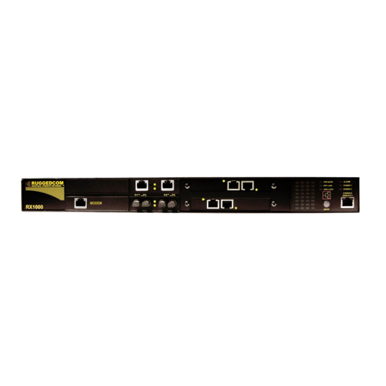
Upgrade the router type to RX1100, • Upload/Download files to and from the router. • Using The LED Status Panel The LED status Panel provides the console port, indicates the status of hardware/software and can initiate a controlled reboot. RuggedCom... -
Page 36: Obtaining Chassis Information
Pressing the pushbutton for more than five seconds will reboot the router. Obtaining Chassis Information The chassis displays the hardware inventory at boot time. This information is captured in the /var/log/messages file after boot. The Web Management interface home page displays the chassis serial number. RuggedCom... -
Page 37: Chapter 2 - Webmin Configuration
But Webmin will provide access to any client that provides the correct password, rendering it vulnerable to brute force attacks. The best way of addressing this problem is to restrict access to specific IP addresses or subnets. By default, IP access control allows all IP addresses to access Webmin. RuggedCom... -
Page 38: Ports And Addresses
Webmin server from outside of your local network. If not, simply configure Webmin to listen on the local interface. By default, Webmin listens on TCP port 10000 for clients. It is possible to change this default behaviour. Change Help Server Figure 18: Webmin Configuration Menu, Change Help Server RuggedCom... -
Page 39: Logging
IP address for the client computer that performed an action. The Clear logfiles every...hours field causes Webmin to rotate its own logs and keep them from overfilling the disk with old logs. Currently, the Log actions by all users field should be left selected. RuggedCom... -
Page 40: Authentication
Webmin Events Log Figure 21: Webmin Events Log This menu allows you to search the Webmin log for changes made by yourself or other administrators. RuggedCom... -
Page 41: Chapter 3 - Configure Webmin Users
A user successfully authenticated by the RADIUS server will have Webmin access corresponding to his/her privilege level, as configured for the user account on the RADIUS server. For information on how to configure user accounts on the RADIUS server, please refer to Appendix E - RADIUS Server Configuration RuggedCom... -
Page 42: Webmin Users Menu
Click the View login sessions button to view all current login sessions. Click the Password Restrictions button to set the password restriction rules. Note: The accounts managed from this menu are local to the RuggedRouter, and are not maintained on a RADIUS server, even if one is configured. RuggedCom... -
Page 43: Edit Webmin User Menu
Click on Session link under the Session ID column to cancel a session. Click the Webmin user link under the Webmin user column to display the Webmin user edit menu for that user. Click the View logs link to display logs for that Webmin user. RuggedCom... -
Page 44: Password Restrictions Menu
If you do not have access to an Internet connection, but do have a UNIX / Linux system with PERL installed, access the local manual pages by typing: man perlreref man perlre man perlretut man perlrequick at the command line. Root privilege is not required to access manual pages. RuggedCom... -
Page 45: Chapter 4 - Configuring The System
If you really want the router to remain powered but permanently inactive, you must issue the shutdown, connect a terminal to the serial port, wait for the router to enter the shutdown shell and issue a CTRL-C. Once again, if you accidentally shutdown the router it will restart after five minutes. RuggedCom... -
Page 46: Change Password Command
This command changes only the root account password used to login to Webmin and the root account via the serial console or SSH. Scheduled Commands Figure 29: Scheduled Commands This menu allows you to schedule a command to run in the future. RuggedCom... -
Page 47: Figure 30: Scheduled Commands Displaying A Command
Finally, enter the command to execute in the Commands to execute field. Note that the command will remain scheduled after reboot. After the command is entered, the Scheduled Commands menu will display any commands and allow you cancel them. Figure 30: Scheduled Commands Displaying a Command RuggedCom... -
Page 48: Scheduled Cron Jobs
Select the times the script is to run from the When to execute table (remember to check the selected button above any column you edit). The Active radio button at the top of the menu temporarily disables the job. After selecting the Create button, the Scheduled Cron Jobs menu will display the job. RuggedCom... -
Page 49: System Hostname
This menu provides a method to set the time and timezone of the router. Note: Changing the system may confuse protocols such as OSPF and RIP, which depend upon an accurate system time. If you use OSPF or RIP, changing the time from this menu will restart them. RuggedCom... - Page 50 ® RuggedRouter User Guide This page intentionally blank RuggedCom...
-
Page 51: Chapter 5 - Configuring Networking
Select the End To End Backup icon to configure an end to end backup connection. Select the Current Routing & Interface Table icon to view the routing table. The Apply Configuration button serves to restore the permanently saved changes and restart Ethernet networking. RuggedCom... -
Page 52: Core Settings
ICMP ECHO request packets if their destination address is a broadcast address. The Syncookie Protection field corresponds to the kernel tcp_syncookie setting. Setting Syncookie Protection to “yes” will cause the kernel to protect against SYN flood attacks. RuggedCom... -
Page 53: Dummy Interface
The first table of this menu configures the default gateway address. Note: Don't configure a default gateway if you plan to provide one from a WAN, PPPoE or modem interface. Don't manually configure configure the default gateway in the /etc/network/interfaces file, configure the default gateway from this menu. RuggedCom... -
Page 54: Configured Static Routes
Routes” link will make the route permanent. Note: There are situations where manually entered routes should not be converted, e.g. routes dynamically added by IPsec and GRE tunnels. Making these routes permanent may cause the daemons that add them to fail. RuggedCom... -
Page 55: Static Multicast Routing
The Comment field shows the current status of the the routing. The Note field below the table shows current active interfaces. In order to start Multicast routing at each and every boot, you must enable it via the System folder, Bootup And Shutdown menu. RuggedCom... -
Page 56: Dns Client
This menu allows you to display and configure host addresses. Host addresses are useful when a non-changing IP address is often used or when DNS is not configured. Follow the Add a new host address link to add an address. RuggedCom... -
Page 57: End To End Backup
1, the second router's gateway will still point towards Network A after a failure of the primary path. Packets from router 1 would reach router 2 through the secondary, but the responses would disappear in the black hole of the failed path. RuggedCom... -
Page 58: Configuring End To End Backup
Current Routing & Interface Table This menu displays the current routing table and the state of the router's interfaces. Consult the Network Utilities chapter for details of this menu. RuggedCom... -
Page 59: Chapter 6 - Configuring Ethernet Interfaces
• Ethernet Interface Fundamentals RuggedCom manufactures dual Ethernet Interface boards in a variety of formats. Some (most notably the optical interfaces) have the same outward appearance but different order numbers. A complete set of descriptions is displayed on the console during boot and can be found after boot in the file /var/cache/ruggedrouter/inventory. -
Page 60: Ruggedrouter Functions Supporting Vlans
Only one PPPoE interface can be created on each Ethernet Interface. Each PPPoE interface name is assigned internally. The name is “pppX”, where X is 10 plus the native Ethernet interface the PPPoE is created upon (e.g. a PPPoE on eth1 is ppp11). RuggedCom... -
Page 61: Ethernet Configuration
The entries in this table can also be used to temporarily disable or re-enable an interface. The Boot Time Configuration table router allows you make changes to the “permanent” configuration of any interface. RuggedCom... -
Page 62: Editing Currently Active Interfaces
The Proxy ARP fields display whether the interface has proxy-arp activated. The Media Type field displays the current media type. Copper interfaces may be configured to Auto-negotiable, 10 BaseT Half Duplex, 10 BaseT Full Duplex, 100 BaseT Half Duplex and 100 BaseT Full Duplex modes. RuggedCom... -
Page 63: Virtual Interfaces
Edit Boot Time Interfaces Figure 50: Editing a Boot Time Interface This menu allows you to make permanent changes to interfaces and to immediately apply those changes if desired. The Save button will save changes to the permanent configuration. RuggedCom... -
Page 64: Pppoe On Native Ethernet Interfaces
The Interface Name field shows created PPPoE interfaces and provides a link to edit the existing configuration or create a new one. The MTU, Use Peer DNS and Default Route fields are the configured information for PPPoE interfaces. The Status field shows the current PPPoE link status. RuggedCom... -
Page 65: Edit Pppoe Interface
The Save button will update all of the changes. The current PPPoE link will be connected. The Delete button will delete the PPPoE interface, closing the current PPPoE link. PPP Logs Figure 53: Display PPP Logs RuggedCom... -
Page 66: Current Routes & Interface Table
This is mainly useful when trying to debug a PPP connection problem. Current Routes & Interface Table The table provided by this command is as described in the Networking menu, Network Utilities sub-menu. It is also provided here as a convenience. RuggedCom... -
Page 67: Chapter 7 - Configuring Frame Relay/Ppp And T1/E1
Equipment (CPE)). The DCE is responsible for managing the link, advertising connections to the DTE and switching packets between connections. The DTE raises individual connections and sends data on them. When using a T1/E1 line to access a public Frame Relay provider, configure the Router as a DTE. RuggedCom... -
Page 68: Location Of Interfaces And Labeling
LEDs will indicate traffic and link status of the port. Consult the section “Using The LED Status Panel” to determine which LEDs correspond to the port. Included With T1E1 T1E1 includes wanpipemon, a utility that can capture traces from the T1E1 line. RuggedCom... -
Page 69: T1/E1 Configuration
This can be done by editing the single initially configured channel and removing timeslots. The unassigned timeslots will be displayed on the main menu in a link that creates channels, as shown below. Figure 56: T1/E1 Network Interfaces After Channel Creation RuggedCom... -
Page 70: Naming Of Logical Interfaces
Channelized hardware allows more than one logical interface. The next part of the identifier indicates the channel the interface uses with a “c” followed by the lowest channel used. The final part of the identifier is either “ppp” or “fr” and the frame relay channel number. RuggedCom... -
Page 71: Editing A T1/E1 Interface
The Line Build Out field “tunes” the shape of the T1 pulses and adjusts their amplitude depending upon distances and the desired attenuation. E1 Settings The Framing and Line Decoding fields for E1 reflect the European variants. The Clocking field performs the same function as that described for T1. RuggedCom... -
Page 72: Editing A Logical Interface (Frame Relay)
“Request”, EEK messages are sent every EEK Timer x T391 seconds. This timer may be configured from 1 to 100 periods in duration. Your network provider will inform you of what is proper for these parameters. RuggedCom... -
Page 73: Frame Relay Dlcis
Repetitive use of this button on other DLCIs assigned to the channel will free the channel up. Editing A Logical Interface (PPP) Figure 60: Edit Logical Interface (PPP) The Local Address, Netmask, Remote Address, Default Gateway and Description fields are as described in the previous section. RuggedCom... -
Page 74: T1/E1 Statistics
YEL (Yellow Alarm) – This alarm is transmitted to the network and alerts it that a failure has been detected. OOF (Out of Frame) – This alarm signifies the occurrence of a particular density of framing error events. This alarm could signify that the wrong framing mode is configured. RuggedCom... -
Page 75: Frame Relay Interface Statistics
Chapter 7 - Configuring Frame Relay/PPP And T1/E1 Frame Relay Interface Statistics Figure 62: Frame Relay Statistics Note that the Frame Relay Trunk Statistics and Frame Relay Trunk Communications Errors tables are common to all Frame Relay DLCIs on the trunk. RuggedCom... -
Page 76: Ppp Interface Statistics
® RuggedRouter User Guide PPP Interface Statistics Figure 63: PPP Link Statistics RuggedCom... -
Page 77: T1/E1 Loopback
If the remote equipment is able to loop, the entire T1/E1 line can be verified. If the remote router is another RuggedCom router, a starting a line loopback will verify both cards and the line. This router will display the count of loopback frames as they arrive. -
Page 78: Current Routes & Interface Table
Note: The upgrade process requires upwards of 15 minutes for each PCI interface card. Because of the lengthy duration required to upgrade the interfaces, RuggedCom does not automatically perform the firmware upgrade. Instead, the scheduling of the upgrade is left to the user. -
Page 79: Chapter 8 - Configuring Frame Relay/Ppp And T3
The RuggedRouter also indicates information about T3 ports on the LED Panel. A pair of LEDs will indicate traffic and link status of the port. Consult the section “Using The LED Status Panel” to determine which LEDs correspond to the port. RuggedCom... -
Page 80: T3 Configuration
Webmin names the logical interfaces for you (but allows you to provide a description). All interfaces start with a “w” to identify them as wan interfaces, followed by the interface number. The next part of the identifier is either “ppp” or “fr” and the frame relay DLCI number. RuggedCom... -
Page 81: Editing A T3 Interface
Relay. The menu is composed of two tables. The first table provides link based configuration, which affect all DLCIs. The second table provides configuration parameters for individual DLCIs. After the first DLCI has been configured, revisiting that DLCI will display a menu that allows additional DLCIs to be configured. RuggedCom... -
Page 82: Editing A Logical Interface (Ppp)
Frame Relay/PPP And T1/E1 chapter with the exception that T3 provides only AIS, LOS, OOF and YEL alarms. Current Routes & Interface Table The table provided by this command is as described in the Networking menu, Network Utilities sub-menu. It is also provided here as a convenience. RuggedCom... -
Page 83: Upgrading Software
If T3 port was upgraded in this way, the upgrade would fail as the T3 link was taken down. Instead, T3 software upgrades modify only the software on the disk. You must schedule a reboot in order to run the new version of T3 software. RuggedCom... - Page 84 ® RuggedRouter User Guide This page intentionally blank RuggedCom...
-
Page 85: Chapter 9 - Configuring Frame Relay/Ppp And Dds
CSU manages electrical levels, isolation and provides loopback to the TELCO. RuggedCom DDS port provides an integrated DTE, DSU and CSU. Location Of Interfaces And Labeling Unlike the Ethernet ports (which are statically located), the location of T1/E1, DDS and ADSL ports in your router depends upon the number of ports and how they were ordered. -
Page 86: Dds Configuration
Refresh this page link to update to the current status. The menu will change after assignment of a logical interface, providing links to logical interface and link statistics. Figure 75: DDS WAN Interfaces after logical interface assignment RuggedCom... -
Page 87: Naming Of Logical Interfaces
Figure 77: Edit Logical Interface (Frame Relay), multiple DLCIs The fields and buttons in this menu are the same as those described in the Editing A Logical Interface (Frame Relay) section of the Configuring Frame Relay/PPP And T1/E1 chapter. RuggedCom... -
Page 88: Editing A Logical Interface (Ppp)
Link Statistics are provided through the “View Link Statistics” link at the bottom of each interface table. Frame Relay and PPP statistics are available through “(Statistics)” links under the interface name column of each interface table. Link Statistics Figure 79: DDS Link Statistics RuggedCom... -
Page 89: Frame Relay And Ppp Interface Statistics
The remote equipment must be able to loop, allowing the entire entire line to be verified. If the remote equipment is another RuggedCom router, starting a line loopback will verify both cards and the line. DDS has no standard for performing digital loopback. - Page 90 ® RuggedRouter User Guide This page intentionally blank RuggedCom...
-
Page 91: Chapter 10 - Configuring Pppoe/Bridged Mode On Adsl
Ethernet. As your PPPoE connection is established a PPP interface will be created. The name will be “pppX” where X is the same as the interface number. Use this interface name in firewall rules. RuggedCom... -
Page 92: Authentication, Addresses And Dns Servers
ADSL card itself and the LED Panel. Four LEDs are associated with the line, next to the interface jack. Power (Green) indicates when the card is active and powered. Link (Green) indicates when the DSL link is established. RuggedCom... -
Page 93: Adsl Configuration
The status of the physical interface, its corresponding logical interface and link statistics are provided. This menu presents connection statuses but does not update them in real time. Click on the Refresh this page link to update to the current status. RuggedCom... -
Page 94: Editing A Logical Interface (Pppoe)
MTU and use whatever it considers to be the default. Note: If the negotiated MTU is different from the requested MTU, a warning will be displayed on the Networking, ADSL menu. RuggedCom... -
Page 95: Editing A Logical Interface (Bridged)
'other end' of the link and is usually assigned by the network administrator or Internet service provider. The Gateway IP Address field defines the IP address to use as the gateway for sending to other sites. This is usually the same as the Remote IP Address. RuggedCom... -
Page 96: Adsl Statistics
If ADSL was upgraded in this way, the upgrade would fail as the ADSL link was taken down. Instead, ADSL software upgrades modify only the software on the disk. You must schedule a reboot in order to run the new version of ADSL software. RuggedCom... -
Page 97: Chapter 11 - Configuring Ppp And Modem
PPP-Link will be green when the modem PPP link is established. It will flash while a connection is being established, or a console dial in session is active. PPP-Data will flash green when there is traffic on the PPP link. RuggedCom... -
Page 98: Ppp Modem Configuration
This menu allows you to display and configure the modem interface, PPP client and server connections. Modem Configuration Figure 86: Edit Internal Modem Configuration Figure 87: Edit External Modem Configuration These menus allow you to configure modem settings and usage features. RuggedCom... - Page 99 &P0 - Make/break ratio of 39/61 at 10 pulses/second. (default) &P1 - Make/break ratio of 33/67 at 10 pulses/second. &P2 - Make/break ratio of 39/61 at 20 pulses/second. &P3 - Make/break ratio of 33/67 at 20 pulses/second. Compression control %C0 - Disable data compression negotiation. RuggedCom...
-
Page 100: Modem Ppp Client Connections
To create a new connection click “Add new” link. To have the router automatically dial a connection at boot time and keep it always active, select which connection should be used from the drop down list of available connection profiles in the “Connect at boot” list. RuggedCom... -
Page 101: Modem Ppp Client
15 attempts is set when the country code is set to Australia when the setting is found to be either 0 or above 15. The Dial Interval field determines how many seconds to wait before re-initiating the link after it terminates. RuggedCom... -
Page 102: Modem Ppp Server
Add and the password will be updated on the existing entry. Note When RADIUS authentication is used, PPP user account information, with the exception of static routes, must instead be configured at the RADIUS server. See Appendix E - RADIUS Server Configuration for details. RuggedCom... -
Page 103: Modem Incoming Call Logs
This page shows the latest log entries for incoming calls. This is mainly useful when trying to debug a problem with establishing incoming connections. Modem PPP Logs Figure 92: PPP Logs This page shows the PPP logs. This is mainly useful when trying to debug a PPP connection problem. RuggedCom... -
Page 104: Modem Ppp Connection Logs
This page shows a list of PPP connections. It shows who connected, when they connected and disconnected, the connection speed, and session traffic. Current Routes & Interface Table The table provided by this command is as described in the Networking menu, Network Utilities sub-menu. It is also provided here as a convenience. RuggedCom... -
Page 105: Chapter 12 - Configuring Ppp And Cellular Modem
The RuggedRouter dedicates two LEDs to indicate cellular modem status: The leftmost LED of the bottom row (LED #29) is the “Line” LED. Solid Green indicates that a PPP link has been established. • Flashing green indicates that PPP link negotiation is in progress. • RuggedCom... -
Page 106: Ppp Cellular Modem Configuration
Figure 94: Cellular Modem Interface This menu allows you to display and configure the cellular modem interface. Cellular Modem Configuration Figure 95: Cellular Modem configuration This menu allows you to configure the cellular modem to connect to a wireless service provider. RuggedCom... -
Page 107: Modem Status
Network Registration Status displays the current registration status of the cellular modem with respect to the GSM/GPRS network. Registered/Home, Registered/roaming or Unregistered will be displayed depending on the current connection status. SIM Card Identification displays the ID of the SIM card currently installed in the cellular modem. RuggedCom... -
Page 108: Modem Ppp Client Connections
If the password is not required, you can enter “none” in this field, or leave it blank. The Default Route checkbox enables automatically setting a default route using this interface whenever it connects. If this is your primary connection you probably want this option enabled. RuggedCom... -
Page 109: Ppp Logs, Ppp Connection Logs
The Dial Interval field determines how many seconds to wait before re-initiating the link after it terminates. PPP Logs, PPP Connection Logs Refer to the chapter, “Configuring PPP and Modem” for information. Current Route and Interfaces Table Refer to the chapter, “Configuring PPP and Modem” for information. RuggedCom... - Page 110 ® RuggedRouter User Guide This page intentionally blank RuggedCom...
-
Page 111: Chapter 13 - Configuring The Firewall
The netfilter system uses rulesets, collections of packet classification rules that determine the outcome of examination of a specific packet. The rules are defined by iptables, a generic table structure syntax and utility program for the configuration and control of netfilter. RuggedCom... -
Page 112: Network Address Translation
NAT can be used in static and dynamic modes. Static NAT masks the private IP addresses by translating each internal address to a unique external address. Dynamic NAT translates all internal addresses to one (or more) external address(es). RuggedCom... -
Page 113: Port Forwarding
5) If your network interface IP is dynamically assigned, configure masquerading. 6) If your network interface IP is statically assigned, configure Source Network address Translation (SNAT). If a sufficient number of IP addresses are provided by the ISP, static NAT can be employed instead. RuggedCom... - Page 114 9) If you are supporting a VPN, add additional rules. 10) Check the configuration using the Shorewall Firewall menu, “Check Firewall” button. 11) Activate the firewall. It is usually a good idea to port scan the firewall after activation and verify that logging is functioning. RuggedCom...
-
Page 115: Shorewall Terminology And Concepts
Note: In order to improve security the router will create a zone “unusd” and unused interfaces to this zone when Shorewall starts. A policy is also installed that blocks access from “unusd” to all other zones. Interfaces are defined in the file /etc/shorewall/interfaces and are modified from the Network Interfaces menu. RuggedCom... -
Page 116: Hosts
Note that order of policies is important. If the last rule of this example were entered first then no connections at all would be allowed. RuggedCom... -
Page 117: Masquerading And Snat
2) In this SNAT rule a static address of 66.11.180.161 is acquired from the ISP. Traffic from the subnet handled by eth2 should be translated to 66.11.180.161 as it sent to the Internet over ppp. The + at the end of “ppp+” causes Shorewall to match any ppp interface. RuggedCom... -
Page 118: Rules
The tcp or udp protocol type. Destination-Port The tcp/udp port the connection is destined for. Source-Port The tcp/udp port the connection originated from. Original- The destination IP address in the connection request as it was Destination-IP received by the firewall. RuggedCom... -
Page 119: Configuring The Firewall And Vpn
The IPsec protocol operates on UDP port 500 and using protocols ah (Authentication Header) and Encapsulating Security Payload (ESP) protocols. The firewall must accept this traffic in order to allow IPsec. If the firewall serves as the VPN gateway, add the following rules: Action Source-Zone Destination-Zone Protocol Dest-Port ACCEPT ACCEPT ACCEPT RuggedCom... -
Page 120: Policy Based Virtual Private Networking
IPSec traffic arriving at the firewall is directed to openswan, the IPSec daemon. Openswan then decrypts the traffic and forwards it back to shorewall on the same interface that originally received it. You will also need a rule to allow traffic to enter from this interface. ACCEPT RuggedCom... -
Page 121: Virtual Private Networking To A Dmz
Virtual Private Networking To A DMZ If the firewall is to pass the VPN traffic through to another device (e.g. a VPN device in a DMZ) then establish a DMZ zone and install the following rules. ACCEPT ACCEPT ACCEPT ACCEPT ACCEPT ACCEPT RuggedCom... -
Page 122: Firewall Configuration
If the firewall starts cleanly, the menu appearance will change to that of the figure below. In order to start the firewall at each and every boot, you must enable it via the System folder, Bootup And Shutdown menu. RuggedCom... -
Page 123: Figure 99: Shorewall Firewall Menu
Stopping the firewall will not disable it. Disable the firewall via the System folder, Bootup And Shutdown menu. The “Show Status” button presents a variety of information summarizing the status of the firewall and routing system. The “Check Firewall” button tests the current configuration to ensure it is valid. RuggedCom... -
Page 124: Network Zones
Note that if you delete a zone you should remove any rules that reference it. Note: There must be exactly one zone of type firewall. Do not delete this zone. You may also make changes by manually editing the zone file. Network Interfaces Figure 101: Firewall Network Interfaces RuggedCom... -
Page 125: Figure 102: Editing A Firewall Network Interfaces
TCP packets arriving on this interface. Checks include Null flags, SYN+FIN, SYN+RST and FIN+URG+PSH; these flag combinations are typically used for “silent” port scans. Packets failing these checks are logged according to the TCP_FLAGS_LOG_LEVEL option in /etc/shorewall/shorewall.conf and are disposed of according to the TCP_FLAGS_DISPOSITION option. RuggedCom... -
Page 126: Network Zone Hosts
Selecting the IPSEC zone Host Option field will identify that the traffic to host in this zone is encrypted. The Save and Delete buttons will allow you to edit or delete the zone host. You may also make changes by manually editing the policy RuggedCom... -
Page 127: Default Policies
The Limit field is the steady state rate and is of the form “X/sec” or “X/min” where X is the number of allowed rule followings. The Burst field denotes the largest permissible burst and defaults to five if not configured. RuggedCom... -
Page 128: Masquerading
The Except for networks field restricts traffic from the specified subnet. The SNAT address field is used to determine whether masquerading or SNAT is being performed. If checked, the entered IP address is used as a SNAT address. RuggedCom... -
Page 129: Firewall Rules
The Destination zone or port field specifies the requests destination zone. The Protocol field specifies the protocol (tcp, udp or icmp) to match. The Source ports and Destination ports fields specifies the requests tcp or udp port numbers to match. RuggedCom... -
Page 130: Static Nat
The External interface field specifies the interface to perform the translation upon. The No IP alias field is used to tell the firewall not create the IP alias for the external address if it has not been created on the external interface yet. RuggedCom... -
Page 131: Tc (Traffic Control) Interfaces, Classes, And Rules
Add field. Reorder the translations by clicking on the arrows under the Move field. Clicking on a link under the Interface field will allow you to edit or delete the rule, as shown below. You may also make changes by manually editing the rule file. RuggedCom... - Page 132 RuggedRouter® User Guide This page intentionally blank RuggedCom...
-
Page 133: Chapter 14 - Traffic Control
HTTP traffic gets at least 20% and at most 50%, and all other traffic should get what is left over but only up to 50% of the bandwidth. The three TC menus would be configured as follows: TC Interfaces Interface Inbound Outbound bandwidth bandwidth eth1 5000kbit 5000kbit RuggedCom... -
Page 134: Tc Classes
We mark all packets with no other matching rule to 4 since that represents the default class (as defined in TC Classes). This allows explicit traffic control of even unspecified network connections. RuggedCom... -
Page 135: Traffic Control Configuration
The Out bandwidth field specifies the maximum outbound bandwidth that the interface can handle. Outbound traffic above this rate is delayed or potentially dropped. Bandwidth is specified in either kilobytes per second (kbps), or kilobits per second (kbit). RuggedCom... -
Page 136: Tc Classes
The Mark to match field specifies what mark value this TC Class will match. The mark may be in the range 1..255 in decimal or hex. The Minimum rate field specifies the minimum bandwidth allocated to this class. The Maximum rate field specifies the maximum bandwidth allocated to this class. RuggedCom... - Page 137 The tos= option field allows you to define a classifier for the given value/mask combination of an IP packet's TOS byte. Note ToS field matches take precedence over the assigned mark The Save button saves the class changes to the TC configuration. The Delete button delete the class from the TC configuration. RuggedCom...
-
Page 138: Tc Rules
Clicking on a link in the Mark column will allow you to edit or delete a traffic classification rule, as shown below. The Manually Edit File button also allows you to make direct changes to the TC Rules configuration file. RuggedCom... -
Page 139: Figure 118: Edit Tc Rule
A mask may again be specified in the / field, to apply to both marks prior to comparison. Mark and mask may be in the range 1..255 in decimal or hex. The Length field specifies the packet length or length range to match. RuggedCom... -
Page 140: Hints On Optimizing The Tc Rule Table
Using the above structure for the TC Rules table, only the first packet of any tcp or udp connection will have to go through all the rules, while every following packet will have its mark restored by the first rule, and then CONTINUE, skipping potentially many matching rules in the remainder of the table. RuggedCom... -
Page 141: Chapter 15 - Configuring Ipsec Vpn
IP datagram. The resultant packet is composed of an new IP header, IPSec headers, old IP header and IP payload. Tunnel mode is most commonly used between gateways, the gateway acting as a proxy for the hosts behind it. RuggedCom... -
Page 142: Policy Vs Route Based Vpns
DES pass. 3DES is the most CPU intensive cipher. AES – The Advanced Encryption Standard protocol cipher uses a 128-bit • block and 128, 192 or 256-bit keys. This is the most secure protocol in use today, and is much preferred to 3DES due to its efficiency. RuggedCom... -
Page 143: Public Key And Pre-Shared Keys
ARP for that interface. This will cause the router to respond to ARP requests on behalf of the client and direct traffic to it over its connection. IPSec relies upon the following protocols and ports: RuggedCom... -
Page 144: The Openswan Configuration Process
Note that in the unlikely event that IPsec uses multiple network interfaces, a stop of any of those interfaces will cause all tunnels to stop. IPsec may have to be manually restarted after configuring network interfaces when multiple tunnels exist. RuggedCom... -
Page 145: Ipsec Vpn Configuration
The “Add a new IPsec VPN connection” link creates a new connection and its icon. The “Import connection from file” link creates new connections from imported data. Select the Server Configuration icon to configure server parameters. Select the Preshared Keys icon to create, delete and edit pre-shared keys. RuggedCom... -
Page 146: Server Configuration
The Network interfaces for IPsec table configures the association between ipsec interfaces and the real interfaces upon which they become available. If the Default field is selected, Openswan will use its current default (Default route interface at the time of writing) to associate the named ipsec interface with. RuggedCom... -
Page 147: Public Key
Select the links under the “Remote Address” column to edit or delete a secret key. The menu will not allow more than one entry to have a specific pair of IP addresses. The menu will not allow a password shorter than eight characters in length. RuggedCom... -
Page 148: List Certificates
The first section (IPsec VPN Connection Details) describes parameters relating to the connection itself. The next two sections (Left System's Settings, Right System's Settings) describe IP networking parameters and RSA signatures at each peer. These two sections are identical and are described once. RuggedCom... -
Page 149: Ipsec Vpn Connection Details
The Perfect Forward Secrecy fields will enable PFS, causing keys to be exchanged in a manner which provides attackers that have compromised a key with no advantage in decoding previously intercepted packets or with subsequent packets. Not all clients support PFS. RuggedCom... -
Page 150: Left/Right System's Settings
Configuration menu, Current Routing & Interface Table icon . A default route will be indicated by a “default” in the Destination column. Export Configuration Selecting the “Export Configuration” button provides a means to capture the connection specification in such a way as to be importable at the remote router. RuggedCom... -
Page 151: Showing Ipsec Status
At least one set of values must match between the left- and right-hand side VPN devices. This is also frequently referred to as the Phase 1 parameters, because the key exchange process is the first thing to occur in establishing a VPN. RuggedCom... -
Page 152: Ipsec X.509 Roaming Client Example
Ensure that the the Certificate Authority generates certificates with a reasonable life and generates keys of at least 1024 bits in length. RuggedCom... -
Page 153: Generate X.509 Certificates
Enable IPSec from the Bootup and Shutdown menu. Visit the IPSec VPN menu and generate a public key. Visit the Server Configuration menu and associate the ipsec0 interface with the desired interface the connection will arrive on (here w1ppp). Create a connection for the clients. Set the parameters as follows: RuggedCom... -
Page 154: Firewall Ipsec Configuration
Ethernet interface that hosts the local network (here eth1) via the Networking Menu, Ethernet sub-menu boot time entry Proxy ARP setting. When a host on eth1 arps for the remote client address, the router will answer on behalf of the client. RuggedCom... -
Page 155: Chapter 16 - Configuring Dynamic Routing
For fast convergence and recovery, OSPF is a much better choice. RIP is a fairly old routing protocol and has mostly been superseded by OSPF. RuggedCom... -
Page 156: Ospf Fundamentals
The subnets at a particular router can be added to its OSPF Area. The router will advertise these subnets to all routers in its area. Note: OSPF areas must be designed such that no single link failure will cause the network to be split into two disjoint networks. RuggedCom... -
Page 157: Router-Id
Routes for subnets which are directly connected to the router but are not part of the OSPF area or RIP network can be advertised if “redistribute connected” is enabled in the OSPF or RIP Global Parameters. Static routes and other routes handled by the kernel can also be redistributed if redistribute kernel is enabled. RuggedCom... -
Page 158: Link Detect
If for example two routers are connected by lower speed wan and higher speed Ethernet links, packets on subnets native to the wan will still be forwarded via Ethernet because of cost. If antispoofing is enabled, the packet will be discarded at the peer OSPF router. RuggedCom... -
Page 159: Administrative Distances
2 and the switched network represent a remote site in which the routers supply a redundant gateway to the hosts via VRRP and the T1/E1 links supply a redundant network connection to the rest of the network. Figure 130: OSPF and VRRP Example RuggedCom... -
Page 160: Area And Subnets
Router 1 will fall back to the Router 1 – Router 2 wan link. Note that it would not be useful to leave the Ethernet 1.1.2.0/24 subnets out of the area and turn on redistribute connected as OSPF would not use the subnets for routing. RuggedCom... -
Page 161: Dynamic Routing Configuration
The Core menu configures link related items such as link-detect and link cost. The RIP and OSPF menu configure these protocols for each interface. Enable Protocols Figure 132: Enable Protocols Menu This menu enables RIP and OSPF for dynamic routing. RuggedCom... -
Page 162: Core
By default it uses the highest IP assigned to an interface on the router. It is recommended that this value be set to a unique fixed IP on each router. RuggedCom... -
Page 163: Core Interface Parameters
This menu contains the configuration and status of OSPF on the router. The OSPF Global Parameters, OSPF Interfaces and Network Areas menus configure OSPF. The Status and View OSPF Configuration menu display the actual status and configuration file contents of OSPF. RuggedCom... -
Page 164: Ospf Global Parameters
Standard follows RFC2178, Cisco and IBM follow RFC3509. Shortcut is covered by the draft-ietf-ospf-shortcut-abr-00.txt document. Standard requires all ABRs to have a backbone connection. The other three methods allow for ABRs that do not have a backbone connection. RuggedCom... - Page 165 By default it uses the highest IP assigned to an interface on the router. It is recommended that this value be set to a unique fixed IP on each router. RuggedCom...
-
Page 166: Ospf Interfaces
The Message Digest Keys fields allows for addition and deletion of keys to use for areas connected to this interface when authentication is set to message-digest. RuggedCom... -
Page 167: Ospf Network Areas
This status menu shows various pieces of information about the current OSPF status. The status of each interface is shown, the current database, the current OSPF neighbors and the current OSPF routing table. View OSPF Configuration This menu shows the current configuration file of OSPF. RuggedCom... -
Page 168: Rip
This is used by the telnet interface of ripd to control access to the configuration. The Telnet Password field sets the password to be used for telnet access to ripd. This is used as the login password of ripd when locally telnetting to port 2604 of the router. RuggedCom... -
Page 169: Rip Key Chains
A key consists of a key string, which is the value used for authentication. It also has the optional lifetime to accept RIP messages with the key, and the optional lifetime to send RIP messages with that key. RuggedCom... -
Page 170: Rip Interfaces
Some network topologies with rings of routers will still have some issues with aging out dead routes even with split horizon enabled but they will still age out faster. If fast network recovery is desired, use OSPF. RuggedCom... -
Page 171: Rip Networks
This status menu shows various pieces of information about the current RIP status. The status of each interface is shown, the current database, the current RIP neighbors and the current RIP routing table. View RIP Configuration This menu shows the current configuration file of RIP. RuggedCom... - Page 172 ® RuggedRouter User Guide This page intentionally blank RuggedCom...
-
Page 173: Chapter 17 - Link Backup
In this way, failures of network links within the cloud are discovered. It is essential that the host always respond to the ping. Another option is to configure a dummy address within the router and ping that address. Figure 144: Link Backup Example RuggedCom... -
Page 174: Use Of Routing Protocols And The Default Route
This menu displays existing main:backup link relationships. Following the links under the Name field to an existing pair will edit them or adds a new one. The Apply Configuration button will apply changes by restarting the link backup daemon. RuggedCom... -
Page 175: Edit Link Backup Configuration
The Main path down timeout field specifies the number of seconds the main trunk must be down before starting the backup trunk. The Main path up timeout field specifies the number of seconds the main trunk must have returned to service before stopping the backup trunk. RuggedCom... -
Page 176: Link Backup Logs
Figure 150: Test Link Backup The test link backup menu tests a link backup by discarding all data received on the main interface. This convinces the daemon that the main trunk is unusable and forces it to fail over to the backup trunk. RuggedCom... - Page 177 Add to this a time that will allow time to navigate the Webmin menus to observe that Link Backup status, link states, and routing are all as expected before, during, and after the Link Backup test. RuggedCom...
- Page 178 ® RuggedRouter User Guide This page intentionally blank RuggedCom...
-
Page 179: Chapter 18 - Configuring Vrrp
VRRP Terminology Each physical router running VRRP is known as a VRRP Router. Two or more VRRP Routers can be configured to form a “Virtual Router”. Each VRRP Router may participate in one or more Virtual Routers. RuggedCom... -
Page 180: Figure 151: Vrrp Example
Note that both routers can always be reached by the hosts at their “real” IP addresses. Two or more VRRP instances can be assigned to be in the same VRRP Group, in which case, they can failover together. RuggedCom... -
Page 181: Figure 152: Vrrp Group Example
These unsolicited ARPs teach the hosts and switches in the network of the current MAC address and port associated with the VRIP. The router will issue a second set of ARPs after the time specified by the Gratuitous ARP delay. RuggedCom... -
Page 182: Vrrp Configuration
The VRRP instances under the Name column define virtual IP groups. Clicking on a link will allow you to edit that instance. The VRRP groups under the Group Name column define virtual IP groups. Clicking on a link will allow you to add members to that group. RuggedCom... -
Page 183: Editing A Vrrp Instance
The Virtual IP netmask prefix field configures the prefix of Virtual IP address netmask. The Save button saves the virtual instance. The Delete button deletes the virtual instance. After you save or delete an instance you must restart the daemon to action your change. RuggedCom... -
Page 184: Editing A Vrrp Group
The entries under the VRRP Interface State column reflect the link state of the interface that the instance runs upon. The entries under the Monitored Interface State column reflect the link state of the monitored interface or “none” if an interface is not configured. RuggedCom... -
Page 185: Chapter 19 - Configuring Traffic Prioritization
Type of Service (TOS) bits in its IP header are examined and used. It is possible to match on source and destination IP address/mask pairs, source and destination port numbers and protocols. The 0.0.0.0/0 address/mask matches any IP address. RuggedCom... -
Page 186: Tos Prioritization
Descriptions Priority Queue Normal Service Normal Minimize Monetary Cost Maximize Reliability Normal MR+MMC Normal Maximize Throughput MT+MMC MT+MR MT+MR+MMC Minimize Delay High MD+MMC High MD+MR High MD+MR+MMC High MD+MT Normal MD+MT+MMC Normal MD+MT+MR Normal MD+MT+MR+MMC Normal RuggedCom... -
Page 187: Prioritization Example
Finally, note that the final traffic filter essentially suppresses TOS inspection by directing all unmatched traffic onto the “low” queue. RuggedCom... -
Page 188: Configuring Traffic Prioritization
Add field. You may also edit a manually created queue by following its link under the Queue Name column, and edit a filter by following it's “Edit” link. RuggedCom... -
Page 189: Prioritization Queues
/etc/services file. This setting matches both udp and tcp ports, unless the Protocol field specifies udp or tcp. The Protocol field specifies a protocol to match against, currently either tcp, udp, icmp, ospf, vrrp or ipsec. The Target Queue field selects one of the available priority queues. RuggedCom... -
Page 190: Prioritization Transmit Queue Length
RuggedCom recommends that the transmit queue length be left at its minimum default value of 1. Higher values, however, may strike a balance between latency an performance. -
Page 191: Chapter 20 - Configuring Generic Routing Encapsulation
You may also set a cost for the tunnel. If another method of routing between Router1 and Router2 becomes available, the tunneled packets will flow through the lowest cost route. You can optionally restrict the packets by specifying the local egress device (in the case of router1, w1ppp). RuggedCom... -
Page 192: Gre Configuration
Note: Each tunnel must have a unique combination of local and remote addresses, or it will not be activated. The Cost field configures the routing cost associated with networking routing that directs traffic through the tunnel. The cost will default to zero if left unset. RuggedCom... - Page 193 The Local Egress Port configures a port to bind the tunnel to. If set, tunneled packets will only be routed via this port and will not be able to escape to another device when the route the to endpoint changes. RuggedCom...
- Page 194 ® RuggedRouter User Guide This page intentionally blank RuggedCom...
-
Page 195: Chapter 21 - Network Utilities
The lower part of the menu provides quick pinging, tracerouting and lookup of hosts. The upper part leads to menus providing more configurable options for these commands. Additionally, Ethernet, WAN and Serial port tracing is provided. A summary of interface statistics and the current routing table is provided. RuggedCom... -
Page 196: Ping Menu
This can make ping behave very slowly if DNS is not properly configured. The Use ICMP instead of UDP? field causes traceroute to probe with ICMP packets. The How many Hops? field limits the maximum number of hops that traceroute will attempt to map. RuggedCom... -
Page 197: Host Menu
Frame Relay Interfaces and Serial server interfaces. The latter two menus will appear only if you have configured Frame Relay or Serial server interfaces. Tcpdump A Network Interface Figure 170: Tcpdump Menu The Interface to capture on field specifies the interface to show traffic on. RuggedCom... -
Page 198: Frame Relay Link Layer Trace A Wan Interface
The Maximum packets captured and Maximum capture time fields limits the amount of traffic captured. Serial Trace A Serial Server Port Figure 172: Serial Server Port Trace Menu The Trace on ports fields specify the serial port to show traffic on. RuggedCom... -
Page 199: Interface Statistics Menu
Note that detailed statistics for T3, T1/E1, DDS and ADSL are available within the menus that configure those interfaces. Current Routing & Interface Table Figure 174: Current Routing & Interface Table RuggedCom... -
Page 200: Interface Status
The entries under the MTU field reflect the Maximum Transmission Unit size for the interface. The entries under the Txqueuelen field reflect the transmit queue length for the interface. RuggedCom... -
Page 201: Chapter 22 - Configuring Serial Protocols
Tracing Serial Port activity • Serial IP Port Features RuggedCom Serial IP provides the following features: Raw Socket Protocol -A means to transport streams of characters from one • serial port on the router, to a specific remote IP address and TCP port. -
Page 202: Serial Protocols Applications
The host will sequentially poll each RTU. Each poll received by the host server is forwarded (i.e. broadcast) to all of the remote servers. All RTUs will receive the request and the appropriate RTU will issue a reply. The reply is returned to the host server, where it is forwarded to the host. RuggedCom... -
Page 203: Serial Protocols Concepts And Issues
This is usually the only packetizer selected when supporting ModBus communications. Finally, the server will always packetize and forward on a full packet, i.e. when the number of characters fills its communications buffer (1024 bytes). RuggedCom... -
Page 204: Use Of Turnaround Delays
RTU. TcpModbus Concepts And Issues Host And Remote Roles Client gateways (such as that implemented by the RuggedRouter) always make the TCP connection to the Server Gateway. The Server Gateway can only accept a connection. RuggedCom... -
Page 205: Port Numbers
RTU fails to respond to requests. Native TcpModbus polling packages will want to receive these messages. Immediate indication of a failure can accelerate recovery sequences and reduce the need for long timeouts. RuggedCom... -
Page 206: Tcpmodbus Performance Determinants
Steps 5-8 represent the case where the request is responded to by the RTU and is forwarded successfully to the master. It includes the “think time” for the RTU to process the request and build the response. RuggedCom... -
Page 207: A Worked Example
Using the figures from the above paragraph, the server being busy would increase the end-to-end delay from 1000 to 1350 ms. The preceding analysis suggests that the Master should time-out at some time after 1350 ms from the start of transmission. RuggedCom... -
Page 208: Dnp (Distributed Network Protocol)
IP Addresses in the DNP Device Address Table (whether learned or statically configured). When a DNP broadcast message is received from the IP network, it is transmitted on all local serial ports configured as DNP ports. RuggedCom... -
Page 209: Serial Protocols Configuration
If any of your serial ports are configured as RawSocket protocol, this menu will configure them. The Serial Protocols Statistics menu will show you the status and statistics for any established sessions. The Line Trace menu will provide a line activity trace for the serial ports. RuggedCom... -
Page 210: Assign Protocols Menu
This menu configures the serial settings and electrical protocol associated with a serial port. Changes are made immediately. RawSocket Menu Figure 179: Raw Socket Menu This menu configures the Raw Socket settings for each port. Changes are made immediately. RuggedCom... -
Page 211: Tcpmodbus Menu
19200 Kbps and 256 char times + 192 ms at baud rates above 19200 Kbps. You may specify a larger value if you think your RTU will take longer to complete transmission than the calculated time. RuggedCom... -
Page 212: Dnp Menu
IP host. The address may be in the range 1 to 65520. Note that both local and remote serial ports must be properly configured. The Rem IP field configures the IP address of the remote host that provides a connection to the DNP device with the configured address. RuggedCom... -
Page 213: Figure 182: Dnp Device Table Settings
DNP device, i.e. the DNP device is attached to the serial port of remote IP host, the value of this parameter is 'Unknown'. Device Address Table This table displays all currently known active DNP devices. RuggedCom... -
Page 214: Serial Protocols Statistics Menu
The Raw Socket Packet Errors field reflect the number of times that a network message was received and could not be enqueued at the serial port because of output buffering constraints. This is usually symptomatic of a remote peer that uses a higher baud rate or local flow control. RuggedCom... -
Page 215: Serial Protocols Trace Menu
Note: Specifying large numbers of ports, entries and capture times can result in a great deal of output. Specifying a large capture time may require the web page to wait that interval if activity is infrequent. RuggedCom... -
Page 216: Serial Protocols Sertrace Utility
66 6f 78 20 6a 75 6d 70 65 64 20 6f 76 65 72 20 fox jumped over 74 68 65 20 6c 61 7a 79 20 64 6f 67 the lazy dog 10:56:47.545 TCPCONN Tx Data from port 1 44b to 10.0.10.236 4991:50002 RuggedCom... -
Page 217: Chapter 23 - Configuring Goose Tunnels
Ethernet is inspected in order to determine which GOOSE group they are in. The frames are then encapsulated in network headers and forwarded (with MAC source and destination addresses intact) to the network as GOOSE packets. IEC61850 recommends that the MAC destination address should be in the range 01:0c:cd:01:00:00 to 01:0c:cd:01:01:ff. RuggedCom... -
Page 218: Layer 2 Tunnel Configuration
The GOOSE Tunnels and GOOSE Statistics menu configures and display statistics for these tunnels. The Activity Trace menu will provide a protocol trace. When enabled, any configuration changes may be made to take effect by selecting the Restart Layer 2 Tunnels daemon button. RuggedCom... -
Page 219: General Configuration Menu
Figure 188: GOOSE Menu This menu configures a GOOSE tunnel. The Ethernet Interface field configures suitable (i.e. VLAN eligible) interfaces to listen for GOOSE frames upon. You may set this field to “none” if the intent is simply to relay network packets. RuggedCom... -
Page 220: Goose Statistics Menu
The Refresh button will cause the page to be reloaded. The Continuous Display button will cause the browser to continuously reload the page showing the differences in statistics from the last display. The difference is not a real time rate in bytes or packets per second. RuggedCom... -
Page 221: Activity Trace Menu
The RTT Measurement field displays Beacon messages used for RTT measurement. Note: Specifying large numbers of ports, entries and capture times can result in a great deal of output. Specifying a large capture time may require the web page to wait that interval if activity is infrequent. RuggedCom... - Page 222 ® RuggedRouter User Guide This page intentionally blank RuggedCom...
-
Page 223: Chapter 24 - Configuring The Dhcp Server
(a single physical networks for which distinct subnets of hosts coexist and request addresses) and groups. The meaning of each option is the same in each case, while the type of target determines which clients it applies to. RuggedCom... - Page 224 Server name: The hostname of the boot server. This only applies to • network booted clients. Lease length for BOOTP clients: How long the IP assigned to a BOOTP • client should be considered valid. RuggedCom...
-
Page 225: Option 82 Support With Disable Nak
2) Click 'add a subnet', and configure it for network address 192.168.1.0 with netmask 255.255.255.0. 3) Set the assigned address range to 192.168.1.101 - 192.168.1.200. 4) Click 'Create' then edit the subnet just created and click 'Edit Client Options'. 5) Set default routers to 192.168.1.1 and save. RuggedCom... -
Page 226: Single Network With Static Ip Assignment
3) Enable the 'Disable NAK of option82 clients for this subnet?' option to prevent confusing some DHCP clients due to the client being on the same network as the DHCP server and the DHCP relay agent (the switch). 4) Save it then edit the subnet just created and click 'Edit Client Options'. RuggedCom... -
Page 227: Multiple Subnets On Separate Vlans Using Option82 On One Switch
12) Set the remote id to the switch MAC address (00:0A:DC:11:22:00 in this case). 13) Set the circuit id to the switches circuit id identifier to the port (00:01:00:02 for VLAN 1 port 2 on a RuggedCom switch). 14) Click 'Create'. 15) Click 'Save'. - Page 228 18) Set the remote id to the switch MAC address (00:0A:DC:11:22:00 in this case). 19) Set the circuit id to the switches circuit id identifier to the port (00:02:00:02 for VLAN 2 port 2 on a RuggedCom switch). 20) Click 'Create'. 21) Click 'Save'.
-
Page 229: Dhcp Configuration
The Start Server button starts the server to check the configuration. To permanently enable DHCP you should enable it in the bootup and shutdown menu. The Apply Changes button applys new settings to the running DHCP server. Use this after making any changes to the configuration. RuggedCom... -
Page 230: Dhcp Shared Network Configuration
The Network name field is a unique name to assign to the shared network. It could be the name of the interface the shared network is on, for example. Within a shared network you can great subnets, hosts, and groups of hosts. RuggedCom... -
Page 231: Dhcp Subnet Configuration
The Subnet description field is used to describe the subnet as desired. The Network address and Netmask fields of the subnet help to specify the span of assigned addresses. Within a subnet you can great hosts, groups of hosts, and address pools. RuggedCom... -
Page 232: Dhcp Group Configuration
Within a group you can create hosts. DHCP Host Configuration Figure 195: DHCP Host Configuration The Host description field is used to describe the host as desired. The Host name field is the unique name to refer to the host within the DHCP configuration. RuggedCom... -
Page 233: Dhcp Pool Configuration
The Clients to allow/deny field can be used to control which clients can get IP address from the pool. See documentation for dhcpd3 for syntax and allowed values. Very rarely needed. The Allow unknown clients setting already handles the most common use of this option. RuggedCom... - Page 234 ® RuggedRouter User Guide This page intentionally blank RuggedCom...
-
Page 235: Chapter 25 - Configuring Ntp
UDP offers. The NTP protocol uses port UDP port 123. Note that if your router employs a firewall and acts as a client it must open UDP port 123. Additionally, if the router acts as a server the firewall must allow connection requests on port 123 as well. RuggedCom... -
Page 236: The Ntp Sanity Limit
NTP daemon about its current state and to request changes in that state. The ntptrace utility is a utility trace a chain of NTP servers back to the primary source. The ntp-keygen utility can be used to generate secure public keys for authentication. RuggedCom... -
Page 237: Ntp Configuration
Set the Broadcast Client option to “Yes” if you wish to act on NTP broadcast messages. The default multicast address used for NTP is 224.0.1.1. Select a custom multicast address with the Custom address field if you wish to use a different addresses. RuggedCom... -
Page 238: Servers Configuration
NTP servers menu. The per-peer configuration information is as described in the previous menu. Viewing NTP Status Figure 200: NTP Status The NTP Status menu displays possible sources and currently used reference clocks RuggedCom... -
Page 239: Viewing The Ntp Log
Chapter 25 - Configuring NTP Viewing The NTP Log Figure 201: NTP Log The NTP Log menu displays the log of recent NTP events. RuggedCom... -
Page 240: Viewing Gps Status
The Number of Satellites shows how many satellites are currently being tracked by the GPS module. The Tracked Satellite Status table shows the ID and signal strength of tracked satellites. Viewing The GPS Log Figure 203: GPS Log The GPS Log menu displays the log of recent GPS events. RuggedCom... -
Page 241: Chapter 26 - Configuring Ssh
Figure 204: SSH Server Note that the SSH server is enabled by default and may be disabled via the System folder, Bootup And Shutdown menu. When enabled, any configuration changes may be made to take effect by selecting the Apply Changes button. RuggedCom... -
Page 242: Authentication
The Allow TCP forwarding field specifies whether TCP forwarding is permitted. If this option is set, clients on a remote network can tunnel TCP connections to machines on the RuggedRouter's network. RuggedCom... -
Page 243: Access Control
ID is not recognized. By default, login is allowed for all groups. The account selector ( ) button can be user to build up a list of allowable groups. The Deny users and Deny members of groups fields specify users and groups to deny connections to. RuggedCom... - Page 244 ® RuggedRouter User Guide This page intentionally blank RuggedCom...
-
Page 245: Chapter 27 - Configuring Irigb And Ieee1588
Ethernet. The RuggedRouter provides a special hardware assisted PTP capability as provided by the RuggedCom PTP card. When used in conjunction with the cards Global Positioning System (GPS) receiver, the router can provide nanosecond accuracy via IEEE1588. -
Page 246: Ptp Master Election
UTC format, broadcast at the start of each second. The RuggedRouter complies to IRIG Standard 200-04 generating formats IRIGB002 and IRIGB003 (PWM) and IRIGB122 and IRIGB123 (AM). RuggedCom... -
Page 247: Irigb Output Formats
When GPS returns, the time will be stepped back to the GPS reference clock. GPS Cable compensation GPS signals received by the antenna will be delayed in time depending upon the type and length of the cable to the router. This delay will introduce inaccuracy in the calculated time and position. RuggedCom... -
Page 248: Irigb/Ieee1588 Configuration
The Reference Clock Selection field selects the order in which to prefer reference clocks. The Cable Compensation field specifies the value, in nanoseconds, that will be used to compensate for the cable type and length. The compensation is done using integer nanosecond values. Fractional decimal values will be truncated. RuggedCom... -
Page 249: Irigb Configuration
The Treat NTP sync'd grandmaster as stratum field assigns the stratum number when grandmaster clock synchronized with remote NTP server but not GPS. The Treat Local Clock sync'd grandmaster as stratum field assigns the stratum number when grandmaster clock synchronized with local clock but not NTP server or GPS. RuggedCom... -
Page 250: Irigb Status
The current local time on the router, the IEEE1588 status, IEEE1588 and UTC time, the offset from master in seconds, the master IP/MAC address and grandmaster MAC address are provided. IRIGB Log Figure 214: IRIGB GPS Status This page reflects reference clock changes in IRIG-B. RuggedCom... -
Page 251: Chapter 28 - Configuring The Intrusion Detection System
The main Snort IDS menu provides the capability to disable individual and groups of rules. It is also possible to add unique rules to the database and to replace the existing set of rules with more experimental rules from the community. RuggedCom... -
Page 252: Alerting Methods
The router is capable of recording about 300 entries/second to the local syslog and 500 entries/second to the alert file. Alerts at rates exceeding the above rates will not be recorded. Snort will require 5 Mbytes of system memory to start with an additional 15 Mbytes of memory for each interface monitored. RuggedCom... -
Page 253: Ids Configuration
Figure 215: Snort Main Menu part 1 The Global Configuration menu section configures parameters that apply to all interfaces. Interfaces Figure 216: Snort Main Menu part 2 The Interfaces section selects the interfaces Snort will monitor. You must restart Snort after changing interfaces. RuggedCom... -
Page 254: Rulesets
It is possible to add your own rule, or one obtained from the open source community (e.g. www.bleedingsnort.com). Rule Lookup by SID The Look Up Rule button accepts a SID and displays its rule. You may elect to disable the rule or learn more information about it. RuggedCom... -
Page 255: Network Settings
Figure 220: Snort Preprocessors Preprocessors are plug-in modules that operate on the captured packets. Preprocessors perform a variety of transformations to make it easier for snort to classify packets. The configuration of preprocessors is beyond the scope of this user guide. RuggedCom... -
Page 256: Alerts & Logging
Edit Config File Snort is extremely flexible and not all capabilities have been described in this user guide. This menu provides the user with the ability to make raw configuration changes to the snort configuration file from within Webmin. RuggedCom... -
Page 257: Chapter 29 - Maintaining The Router
An alert filter is a user defined configuration to define the forwarders destination of active alerts. Any active alerts with Renotify Interval set to non-zero value and matches with the filter level will be forwarded to the defined forwarder destination. Alert Main Menu Figure 222: Alert Main Menu RuggedCom... -
Page 258: Alert Configuration
The Default Filter Level for Command Line configures the lowest alert level to show when user login by console or ssh. The Save button saves all changes of general configuration. The Create New Filter button allows you to create a new forwarder filter for active alerts. RuggedCom... -
Page 259: Alert Filter Configuration
The Create New Definition button allows you to create a user defined alert definition entry. Click on one of the link under the Codepoint column allows you to change the configuration for that alert definition entry. RuggedCom... -
Page 260: Change Alert Definition
The Parameters for Shell table allows user to configure additional parameters if the alert definition entry type is Shell. The Sample Interval configures how often should the system run configured shell command to get a sample. The Command configures the shell command to run. RuggedCom... - Page 261 The Falling Threshold configures the value that will trigger an event when the value of the variable decreases past this value. The Startup configures the condition that will cause the initial event. RuggedCom...
-
Page 262: Industrial Defender
Industrial Defender Agent by: Configuring the IP addresses of the SEM unit and RuggedRouter • Launching a key exchange sequence with the SEM • Helping to configure remote system logging operation • RuggedCom... -
Page 263: Configuring Industrial Defender Addresses
SEM unit, and then click Obtain a new key. In case of error, e.g. a password mismatch, an error message to that effect will be shown at the top of the page. Figure 229: Industrial Defender Configuration - key obtained RuggedCom... -
Page 264: Configuring Remote Syslogging
Industrial Defender Agent itself by enabling the idefender entry in the Bootup and Shutdown menu. A properly configured SEM unit will now be receiving data from the RuggedRouter. Please note that when the idefender process is stopped, the remote syslog entry to the SEM unit is automatically removed. RuggedCom... -
Page 265: Gauntlet Security
IPv4 Visit the Network Interfaces sub-menu and assign interfaces to the zones. For • example, eth1 = net, eth2 = loc. Visit the Default Policies sub-menu and assign the following policies: Source zone Destination zone Policy ACCEPT ACCEPT DROP RuggedCom... -
Page 266: Step 2 Of 3 - Gauntlet Configuration
Gauntlet. Note that exposing any protocol or networked service has the potential of being a security risk and should not be done without good reason. Contact RuggedCom support for assistance if you wish to add other rules to the set recommended here. -
Page 267: Gauntlet Status Menu
The status menu provides a list of validated open connections. Figure 230: Gauntlet Security Appliance Menu Upgrading Gauntlet During an upgrade, the Gauntlet daemon may be required to restart. During the upgrade all existing Gauntlet protected connections will be closed. RuggedCom... -
Page 268: Backup And Restore
Note the following caveats: Chassis specific items such as serial number, hardware inventory and • MAC addresses are not saved, Log and history files are not saved, • Information stored in the root and user accounts are not saved. • RuggedCom... -
Page 269: General Configuration
The Save Archive Configuration to field specifies the configuration server hostname (or IP address) and the directory in which to save configuration archives. The Save Webmin Configuration to field specifies the configuration server hostname (or IP address) and the directory in which to save Webmin configuration archives. RuggedCom... -
Page 270: Configuration Rollback
300 seconds. The timeout mechanism will be in place from the time the user presses the Start Configuration Rollback Monitoring button until he eventually goes back to the Configuration Rollback menu and presses the Accept Current Configuration button: Figure 235: Configuration Rollback menu ready to accept changes RuggedCom... -
Page 271: Archive History
The Archives to upload fields select archives to upload to the router. The Browse... button will allow you to select an archive. Applying the Upload to Router button will upload the specified archive to the router. Archive Backup RuggedCom... -
Page 272: Archive Restore
Otherwise Internet Explorer will rename the file after uploading, preventing its use in a subsequent archive restore. Archive Restore The restore process begins by selecting an archive to restore from. Following an archive link will restore the archive and reboot the router. RuggedCom... -
Page 273: Figure 239: Archive Restore Menu
The latestarchive and factorydefault archives are always able to be restored. Click on one of the links under Archive Name to start the restore. Starting the restore results in the following display. Figure 240: Start Restore To begin the restoring process, click the Start Restore button. RuggedCom... -
Page 274: Archive Difference Tool
Following the links under File Name column will show a files difference between the two targets. The difference will be shown by two methods. The difference between the two targets will be first be shown in a side by side scrollable comparison. RuggedCom... -
Page 275: Figure 243: Show Difference For Selected File Between Two Targets
Note that the copying configurations may not make any actual operating changes until the systems that own them are restarted. If the source archive has a file that is not present in the Current Configuration, it is possible to view that file and then copy it into Current Configuration. RuggedCom... -
Page 276: Snmp Configuration
Bootup And Shutdown menu. Note: Prior to ROX 1.10.0, SNMP was manually configured used the com2sec, group, view and access directives. If so configured, the SNMP menu will prompt you to convert the configuration to one it can manage. RuggedCom... -
Page 277: System Configuration
Figure 247: Network Addressing Configuration Menu, Addresses to listen on The table of Addresses to listen on includes the list of currently configured and active IP addresses, and whether the address is currently listened on. The New field allows for the addition of other IP addresses. RuggedCom... -
Page 278: Access Control
Figure 249: Access Control Menu, SNMP V3 The second part of the Access control menu allows creation and deletion of V3 users. The User Name field selects the name of the new user. The Access field determines whether the community is read-only or read/write. RuggedCom... -
Page 279: Trap Configuration
The SNMP V1 and V2c Trap Destinations part of the menu allows the creation and deletion of trap destinations. The Type field specifies the exchange used with this destination, either V1 trap, V2c trap or V2c inform. The IP address and Trap Community fields specifies the receivers IP address and community name. RuggedCom... -
Page 280: Figure 252: Trap Destinations V3
The Engine ID parameter is necessary for inform type notification destinations only, and must be configured by the trap receiver in order to receive these notifications. The Minimum Security, Authentication Protocol, Authentication Passphrase, Privacy Protocol and Privacy Passphrase fields are as described above. RuggedCom... -
Page 281: Mib Support
The MIB module for managing UDP implementations. SNMP-VIEW-BASED-ACM-MIB View-based Access Control Model for SNMP. SNMP-FRAMEWORK-MIB The SNMP Management Architecture MIB. SNMP-MPD-MIB The MIB for Message Processing and Dispatching. SNMP-USER-BASED-SM-MIB The management information definitions for the SNMP User-based Security Model. RuggedCom... -
Page 282: Radius Authentication
RuggedRouter will wait for a response. An authentication request could thus require up to the sum of the timeouts of all configured servers. The user has the option of designating different servers to authenticate either LOGIN, PPP or WEMBIN services separately or in combination. RuggedCom... -
Page 283: Radius Authentication Configuration
Figure 254: RADIUS Authentication Server Parameters This menu configures, tests and deletes RADIUS server entries. The Hostname/IP field configures the server IP address. The Port Number fields selects the default port number of 1812 or selects another specific port. RuggedCom... - Page 284 The Shared Secret field configures the unique password used by this server. The time Timeout field selects the maximal time to wait before trying the next server. The Service field configures whether the server authenticates LOGIN, WEBMIN, PPP LOGIN or any combination of these types. RuggedCom...
-
Page 285: Outgoing Mail
The Hostname field specifies the hostname to be written into the email header upon transmission. Helpful Hint You can generate emails from scheduled commands and scripts with “(echo "To: ops@myco"; echo -e "Subject: Hello!\n"; some-command) | sendmail -t”. RuggedCom... -
Page 286: Chassis Parameters
The last power down time reflects the time power was removed from the chassis as a result of a power failure, commanded reboot or an watchdog initiated reboot. System alarms will be generated for out-of-range parameters and watchdog initiated reboots. RuggedCom... -
Page 287: Power Over Ethernet
RuggedRouter implements PoE mode A, supplying up to 400mA at up to 48V on pins 3 and 6 (T568A pair 2) and return on pins 1 and 2 (T568A pair 3). Figure 257: PoE pinout on 10/100BaseT port RuggedCom... -
Page 288: Power Over Ethernet Menu
The Voltage, Current and Power columns show the voltage, current and power value (in unit of Volt, mill Ampere and Walt, respectively) when there is power delivery on this port. The Status column shows whether there is any error detected on this port. RuggedCom... -
Page 289: System Logs
– This log catches reports of critical failures. There should never • be any messages in this log. Your RuggedCom support representative may ask you to inspect this file. kern.log – This log contains messages issued by the kernel (the most •... -
Page 290: Remote Logging
System Logs sub-menu. Finally, you may forward all information to the remote logger by creating a new system log entry and specifying “All” Facilities and all priorities, and checking the Syslog server on field with an appropriate address. RuggedCom... -
Page 291: Upgrade System
The major release number Y is increased when important new features are added. This is called a “Major” release. The minor release number Z is increased when minor functionality is added or bug repairs are made. This is called a “Minor” release. RuggedCom... -
Page 292: When A Software Upgrade Requires A Reboot
Automatic Upgrade It can be programmed to check a server on your network at a specific time each day, upgrading to the newest release. RuggedCom understands that some administrators may wish to pre-test package upgrades on specific machines before performing a network wide upgrade. -
Page 293: Change Repository Server
If you configure this field with a major/minor/patch release number such as “rr1.7.2”, the router will only upgrade from that release. The Bandwidth Limiting selector allows you to select the bandwidth available for upgrading software. RuggedCom... -
Page 294: Automatic Upgrading
Webmin will automatically restart after the upgrade completes, after which time you may log back in. Installing A New Package Figure 266: Installing A New Package The Install A New Package feature uploads and installs packages to the router. RuggedCom... -
Page 295: Pre-Upgrade/Post-Upgrade Scripts
Log File of Last Upgrade” button on the Software Upgrade System page. Example of a post-upgrade script: The following post-upgrade script will send an email notification when upgrade completes (assuming SMTP is configured properly). #!/bin/bash echo "Subject: Software upgrade for Release rr1.9.0 on `hostname` completed" > /tmp/mail echo "To: controlcenter@ruggedcom.com" >> /tmp/mail echo "Software upgrade for Release rr1.9.0 on `hostname` completed at `date`" >> /tmp/mail echo >> /tmp/mail cat /tmp/mail | ssmtp controlcenter@ruggedcom.com rm f /tmp/mail... -
Page 296: Uploading And Downloading Files
You may specify the files path directly or click on the browse button to open a file search dialog box. Select the file to upload and close the dialog box. Then click the Upload to your host button. RuggedCom... -
Page 297: Chapter 30 - Security Considerations
11.If using a firewall, configure and start the firewall before attaching the router to the public network. Configure the firewall to accept connections from a specific domain. 12. Configure remote system logging to forward all logs to a central location. RuggedCom... - Page 298 ® RuggedRouter User Guide This page intentionally blank RuggedCom...
-
Page 299: Appendix A - Setting Up A Repository
This host must be able to act as a web server or ftp server. The host must also be able to access the RuggedCom web site in order to download new releases of software from RuggedCom. -
Page 300: Upgrading The Repository
User Guide Upgrading The Repository RuggedRouter releases are obtained from the RuggedCom web site as ZIP files. Download the ZIP file to your regular and/or test release directories and unzip them. You may delete the original ZIP file if desired. -
Page 301: Upgrading Considerations
Administrators should also be wary of routers which concentrate locally connected routers as the upgrade bandwidth consumed on the network link could reach the sum of all bandwidth limiting settings. Routers using Frame Relay with CIR under-subscription may also encounter lengthier downloads because of retransmission. RuggedCom... -
Page 302: Appendix B - Re-Flashing Router Software
The release process involves the following steps: 1. The re-flashable image file is downloaded from RuggedCom to a web server. 2. The router to re-flash is attached via one of its Ethernet ports to the web server (either directly or via a network), configured and tested. -
Page 303: Appendix C - Installing Apache Web Server On Windows
A number of customers have asked for advice and instructions on setting up a web server on Windows. RuggedCom recommends the Apache web server, because it is secure, robust, easy to install and configure as well as being able to be installed on a wide variety of Windows platforms. - Page 304 User Guide Return to the web browser used earlier to verify Apache and refresh the screen. It should now reflect the contents of your RuggedRouter release directory. You should now be able to perform an upgrade from a router. RuggedCom...
-
Page 305: Appendix D - Installing Iis Web Server On Windows
Visit the router you wish to upgrade and visit the Maintenance menu, Upgrade System sub-menu. Click on the Change Server button and set the Repository Server field (e.g. http:// 192.168.0.1/ruggedcom). Set the Release Version field to rr1. Save the configuration and return to the Maintenance menu. Set the Only show which packages would be upgraded radio button to No and click on the Upgrade Now button to start the upgrade. -
Page 306: Appendix E - Radius Server Configuration
Specific field, “privilege-level”, which is used by Webmin to assign assign specific capabilities to Webmin users on a per user basis. Currently, the only privilege-level is that of “root”, but RuggedCom will be introducing additional levels in upcoming releases. FreeRadius The following steps to add Vendor-Specific attributes to the freeradius RADIUS server. -
Page 307: Figure 270: Ias Window - Edit Remote Access Policy
Figure 270: IAS Window - Edit Remote Access Policy 4. In Edit Profile window, Click Add... button Figure 271: IAS Window - Edit Profile 5. In Add Attribute window, select Vendor-Specific line, and click Add button. Figure 272: IAS Window – Add Attribute RuggedCom... -
Page 308: Figure 273: Ias Window - Multivalued Attribute Information
2; in the Attribute format listbox, select String, in the Attribute value editbox, input the desired privilege level (in the above case, it is operator, in your case, currently you should input root). Figure 275: IAS Window – Configure VSA (RFC compliant) RuggedCom... -
Page 309: Appendix F - Vpn/L2Tp Configuration In Windows
11. Click the “OK” button to save the Properties settings. 12. Now you are back to “Connect” window; enter your user name and password to begin the connection. More information about how to import a certificate in Windows XP/2000 can be found at the link: http://www.jacco2.dds.nl/networking/openswan-l2tp.html#Certificates RuggedCom... -
Page 310: Index
Client Options..........................221 Examples.............................223 Fundamentals..........................221 Option 82 Support........................223 DNS..............................54 Dummy Interface..........................51 Email..............................Configuring SMTP........................283 End To End Backup..........................55 Ethernet Interfaces..........................Active............................60 Boot Time ............................61 Proxy ARP............................60 Virtual ............................61 Firewall..............................Fundamentals..........................109 Frame Relay............................End to End Keepalive........................70 Introduction...........................65 Link Failure...........................70 N391..............................70 N392..............................70 RuggedCom... - Page 311 Modem PPP..........................100 PPPoE............................93 T1/E1 Frame Relay........................71 Virtual Ethernet..........................61 Web Access Control........................35 Web Browser Address........................31 IPV6 Support............................50 IRIGB..............................Output Formats...........................245 Reference Clocks........................245 Kernel Settings............................icmp_echo_ignore_all........................50 icmp_echo_ignore_broadcasts......................50 rp_filter............................50 tcp_syncookie..........................50 LED Status Panel ..........................33 LEDs..............................ADSL Ports...........................90, 103 DDS Ports.............................83 Ethernet Ports........................57, 199 RuggedCom...
- Page 312 Multicasting ..........................233 NTP Sanity Limit........................234 Peers ............................233 Servers ............................233 Stratum............................233 Utilities............................234 OSPF..............................Active vs Passive Interfaces..................155, 164, 168 Administrative Distances......................157 Antispoofing..........................156 Areas............................154 Authentication........................156, 164 Hello And Dead Intervals....................155, 164 Link Costs........................156, 161, 163 Link Detect..........................156, 161 Link State Advertisements......................154 Neighbours..........................154 RuggedCom...
- Page 313 Routing table, Viewing......................56, 197 Scheduled Commands ........................44 Scheduled Cron Jobs ........................46 Security..............................IP Access Control..........................35 SSH Access Control........................241 Webmin listening address ......................36 Webmin Password........................44 Serial Numbers..........................34 Sertrace............................214 Services..............................Enabling and Disabling from setup menu..................28 Enabling And Disabling from Webmin..................43 RuggedCom...
- Page 314 Time..............................Changing Through setup menu.....................29 Changing through Webmin ......................47 Timezone............................... Changing Through setup menu.....................29 Traffic Control..........................131 Classes............................134 Fundamentals..........................131 Interfaces.............................133 optimizing...........................138 Rules............................136 Virtual Lan Interfaces........................... Adding............................61 Supported Functions........................58 VPN............................... Configuring..........................139 Connections ..........................146 Encryption Protocol ........................140 Fundamentals......................139, 153, 154 NAT Traversal..........................145 RuggedCom...
- Page 315 Index Policy Vs Route Based........................140 Preshared Keys..........................145 Public Key ..........................145 Server Configuration........................144 Showing Status..........................149 VRRP..............................Fundamentals..........................177 keepalived...........................177 wanpipemon............................196 Web Interface............................31 Router Software..........................300 Web Server.............................303 RuggedCom...
Need help?
Do you have a question about the RuggedRouter RX1000 and is the answer not in the manual?
Questions and answers