
Related Manuals for RuggedCom RS900L


Summary of Contents for RuggedCom RS900L
- Page 1 Preface Introduction Installing the Device RUGGEDCOM RS900L Communication Ports Technical Specifications Dimension Drawings Installation Guide Certification 10/2013...
-
Page 2: Security Information
RUGGEDCOM RS900L Installation Guide Copyright © 2013 Siemens AG All rights reserved. Dissemination or reproduction of this document, or evaluation and communication of its contents, is not authorized except where expressly permitted. Violations are liable for damages. All rights reserved, particularly for the purposes of patent application or trademark registration. -
Page 3: Table Of Contents
RUGGEDCOM RS900L Installation Guide Table of Contents Table of Contents Preface ........................ Alerts ..............................v Related Documents ..........................v Accessing Documentation ........................v Training .............................. vi Customer Support ..........................vi Chapter 1 Introduction ......................1.1 Feature Highlights ........................1 1.2 Ports, Controls and Indicator LEDs ....................2 Chapter 2 Installing the Device .................... - Page 4 RUGGEDCOM RS900L Table of Contents Installation Guide 4.2 Failsafe Relay Specifications ...................... 19 4.3 Copper Ethernet Port Specifications .................... 20 4.4 Fiber Optic Ethernet Port Specifications ..................20 4.5 Operating Environment ....................... 21 4.6 Mechanical Specifications ......................21 Chapter 5 Dimension Drawings ..................
-
Page 5: Preface
Installation Guide Preface Preface This guide describes the RUGGEDCOM RS900L. It describes the major features of the device, installation, commissioning and important technical specifications. It is intended for use by network technical support personnel who are responsible for the installation, commissioning and maintenance of the device. -
Page 6: Training
RUGGEDCOM RS900L Preface Installation Guide For any questions about the documentation or for assistance finding a specific document, contact a Siemens sales representative. Training Siemens offers a wide range of educational services ranging from in-house training of standard courses on networking, Ethernet switches and routers, to on-site customized courses tailored to the customer's needs, experience and application. -
Page 7: Introduction
RS900L to be placed in almost any location. The RS900L is packaged in a compact, galvanized steel enclosure that allows either DIN or panel mounting for efficient use of cabinet space. The RS900L provides an integrated power supply with a wide range of voltages (88-300 VDC or 85-264 VAC) for worldwide operability or dual-redundant, reversible polarity, 12 VDC, 24 VDC and 48 VDC power supply inputs for high availability applications requiring dual or backup power inputs. -
Page 8: Ports, Controls And Indicator Leds
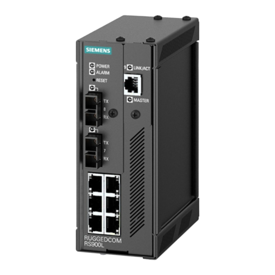
• CSA/UL 60950-1 safety approved to 85 °C (185 °F) Section 1.2 Ports, Controls and Indicator LEDs The RS900L features various ports, controls and indicator LEDs on the front panel for configuring and troubleshooting the device. Ports, Controls and Indicator LEDs... - Page 9 RUGGEDCOM RS900L Chapter 1 Installation Guide Introduction Figure 1: Front Panel 1. Power Indicator LEDs 2. Alarm Indicator LED 3. Reset Button 4. RS232 Serial Console Port Power Indicator LEDs The power indicator LED illuminates when power is being supplied to the device.
- Page 10 RUGGEDCOM RS900L Chapter 1 Installation Guide Introduction Ports, Controls and Indicator LEDs...
-
Page 11: Installing The Device
Section 2.1 Mounting the Device The RS900L is designed for maximum mounting and display flexibility. It can be equipped with connectors that allow it to be installed in a 35 mm (1.4 in) DIN rail or directly on a panel. -
Page 12: Mounting The Device On A Din Rail
Mounting the Device on a DIN Rail For DIN rail installations, the RS900L can be equipped with a DIN rail bracket pre-installed on the back of the chassis. The bracket allows the device to be slid onto a standard 35 mm (1.4 in) DIN rail. -
Page 13: Connecting Power
Install the supplied screws to secure the adapters to the panel. Section 2.2 Connecting Power The RS900L supports a single integrated high AC/DC or low DC power supply NOTE • For 110/230 VAC rated equipment, an appropriately rated AC circuit breaker must be installed. -
Page 14: Connecting High Ac/Dc Power
Chapter 2 RUGGEDCOM RS900L Installing the Device Installation Guide • Insertion Loss: < 0.1 dB at 10 MHz • Peak Surge Current: 10 kA, 8x20µs waveform The following sections describe how to connect power to the device: • Section 2.2.1, “Connecting High AC/DC Power”... -
Page 15: Connecting Low Dc Power
RUGGEDCOM RS900L Chapter 2 Installation Guide Installing the Device Figure 4: Terminal Block Wiring 1. Positive/Live (+/L) Terminal 2. Negative/Neutral (-/N) Terminal 3. Surge Ground Terminal 4. Braided Ground Cable Connect the negative wire from the power source to the negative/neutral (-/N) terminal on the terminal block. -
Page 16: Connecting The Failsafe Alarm Relay
Chapter 2 RUGGEDCOM RS900L Installing the Device Installation Guide Figure 5: Terminal Block Wiring 1. Positive Terminal 2. Negative Terminal 3. Surge Ground Terminal 4. Braided Ground Cable Connect the negative wire from the power source to the negative terminal on the terminal block. -
Page 17: Connecting To The Device
Connecting to the Device The following describes the various methods for accessing the ROS console and Web interfaces on the device. For more detailed instructions, refer to the ROS User Guide for the RS900L. Serial Console Port Connect a PC or terminal directly to the serial console port to access the boot-time control and ROS console interface. -
Page 18: Cabling Recommendations
Siemens does not recommend the use of copper cabling of any length for critical, real-time substation automation applications. All copper Ethernet ports on RUGGEDCOM products include transient suppression circuitry to protect against damage from electrical transients and conform with IEC 61850-3 and IEEE 1613 Class 1 standards. -
Page 19: Communication Ports
To determine which ports are equipped on the device, refer to the factory data file available through ROS . For more information on how to access the factory data file, refer to the ROS User Guide for the RS900L. -
Page 20: Fiber Optic Ethernet Ports
Chapter 3 RUGGEDCOM RS900L Communication Ports Installation Guide WARNING! Electric shock hazard – risk of serious personal injury and/or equipment interference. If shielded cables are used, make sure the shielded cables do not form a ground loop via the shield wire and the RJ45 receptacles at either end. -
Page 21: Eovdsl Ports
RUGGEDCOM RS900L Chapter 3 Installation Guide Communication Ports Figure 11: LC Port Figure 10: MTRJ Port 1. Tx Connector 2. Rx Connector 1. Tx Connector 2. Rx Connector Figure 12: SC Port Figure 13: ST Port 1. Tx Connector 2. Rx Connector 1. -
Page 22: Eovdsl Wiring
Chapter 3 RUGGEDCOM RS900L Communication Ports Installation Guide Status LED State Description No link detected NOTE All RJ11 connectors conform to the standard telephony pin configuration. The following is the pin-out for the RJ11 connectors: Description Reserved (Do Not Connect) -
Page 23: Configuration And Setup
Section 3.3.2 Configuration and Setup If the RS900L and another device both have Universal EoVDSL ports, configure one device to be the Master and the other the Slave. If both devices have a Long-Reach EoVDSL port, no Master/Slave configuration is necessary, since the ports will already be fixed as Master or Slave. - Page 24 Chapter 3 RUGGEDCOM RS900L Communication Ports Installation Guide Downstream / Time to Achieve Port Up Distance (km) Distance (feet) Upstream (Mbps) in Auto Mode (Seconds) 2.50 8200 The following performance is typical with Long-Reach EoVDSL ports: Time to Achieve Downstream (Master...
-
Page 25: Technical Specifications
RUGGEDCOM RS900L Chapter 4 Installation Guide Technical Specifications Technical Specifications The following sections provide important technical specifications related to the device and available modules: • Section 4.1, “Power Supply Specifications” • Section 4.2, “Failsafe Relay Specifications” • Section 4.3, “Copper Ethernet Port Specifications”... -
Page 26: Copper Ethernet Port Specifications
NOTE Order codes are contained within each product when assembled and configured at the factory. Refer to the ROS User Guide for the RS900L for information on how to obtain the factory configuration data. NOTE • All optical power numbers are listed as dBm averages. To convert from average to peak add 3 dBm. -
Page 27: Operating Environment
RUGGEDCOM RS900L Chapter 4 Installation Guide Technical Specifications Cable Tx λ Distance Power Order Connector Tx min. Tx max. Mode Type (typ.) Sensitivity Saturation (typ.) Budget Code Type (dBm) (dBm) (μm) (nm) (dBm) (dBm) (km) (dB) 1310 9/125 1310 9/125... - Page 28 RUGGEDCOM RS900L Chapter 4 Installation Guide Technical Specifications Mechanical Specifications...
-
Page 29: Dimension Drawings
RUGGEDCOM RS900L Chapter 5 Installation Guide Dimension Drawings Dimension Drawings NOTE All dimensions are in millimeters, unless otherwise stated. 65.13 116.59 7.87 Figure 15: Overall Dimensions... - Page 30 Chapter 5 RUGGEDCOM RS900L Dimension Drawings Installation Guide 134.09 13.64 101.60 11.176 78.74 120.65 Figure 16: Panel and DIN Rail Mount Dimensions...
-
Page 31: Certification
RUGGEDCOM RS900L Chapter 6 Installation Guide Certification Certification The RS900L device has been thoroughly tested to guarantee its conformance with recognized standards and has received approval from recognized regulatory agencies. • Section 6.1, “Agency Approvals” • Section 6.2, “FCC Compliance”... -
Page 32: Emi And Environmental Type Tests
Chapter 6 RUGGEDCOM RS900L Certification Installation Guide Section 6.4 EMI and Environmental Type Tests The RS900L has passed the following EMI and environmental tests. IEC 61850-3 Type Tests Test Description Test Levels Severity Levels IEC 61000-4-2 Enclosure +/- 8 kV... -
Page 33: Environmental Type Tests
DC Power ports 5 kV AC Power ports 5 kV IEEE 1613 (C37.90.x) EMI Immunity Type Tests NOTE The RS900L meets Class 2 requirements for an all-fiber configuration and Class 1 requirements for copper ports. IEEE 1613 IEEE Test Description Test Levels Clause C37.90.3... - Page 34 Chapter 6 RUGGEDCOM RS900L Certification Installation Guide Test Description Test Levels Severity Levels IEC 60068-2-30 Humidity (Damp Test Db 95% (non-condensing), Heat, Cyclic) 55 °C (131 °F), 6 cycles IEC 60255-21-1 Vibration 2 g @ 10-150 Hz Class 2 IEC 60255-21-2...
Need help?
Do you have a question about the RS900L and is the answer not in the manual?
Questions and answers