Table of Contents
Advertisement
Quick Links
Advertisement
Table of Contents

Related Manuals for Microscan N2210WZ


Summary of Contents for Microscan N2210WZ
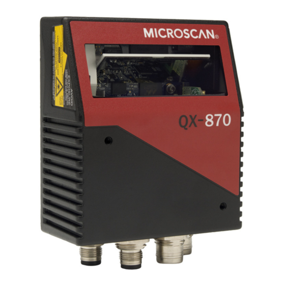
- Page 1 QX-870 Industrial Raster Scanner User’s Manual P/N 83-000870 Rev C...
-
Page 2: Technical Support
Copyright and Disclaimer Copyright ©2010 Microscan Systems, Inc. ISO 9001 Certified Issued by TüV USA All rights reserved. The information contained herein is proprietary and is provided solely for the purpose of allowing customers to operate and/or service Microscan manufactured equipment and is not to be released, reproduced, or used for any other purpose without written permission of Microscan. -
Page 3: Table Of Contents
Introduction Table of Contents Chapter 1 Quick Start Step 1 Check Hardware ................1-2 Step 2 Connect the System ..............1-3 Step 3 Position Scanner and Symbol ............1-4 Step 4 Install ESP..................1-5 Step 5 Select Model ................1-6 Step 6 Connect .................. - Page 4 Table of Contents Terminal Window Menus ................. 6-6 Chapter 7 Utilities Serial Utility Commands ................7-2 Read Rate ....................7-4 Counters ....................7-6 Device Control ..................7-8 Differences from Default................7-9 Master Database ................... 7-10 Digital Bar Code ..................7-16 Firmware ....................
- Page 5 Introduction About the QX-870 Industrial Raster Scanner The key features of the QX-870 Industrial Raster Scanner are: • Quick and easy configuration with Ultra-Lock™ cables and connectors • X-Mode™ symbol reconstruction and aggressive decode algorithm • Embedded Ethernet TCP/IP and EtherNet/IP™ •...
- Page 6 Warning and Caution Summary Warning and Caution Summary This equipment has been tested and found to comply with the limits for a Class A digital device, pursuant to part 15 of the FCC Rules. These limits are designed to provide reasonable protection against harmful interference in a residential installation.
- Page 7 Introduction Warning and Caution Summary (cont.) • Wavelength: 655 nm • Beam Divergence: 0.4˚ (typ.) • Pulse Duration: 40~186µs • Maximum Power: 1.75mW • Location of the QX-870’s laser aperture: Laser Aperture CAUTION: Use of controls or adjustments or performance of procedures other than those specified herein may result in hazardous radiation exposure.
- Page 8 Warning and Caution Summary Warning and Caution Summary (cont.) Warning Label Placement This label is located on the QX-870 Compact Industrial Scanner: On Side On Bottom viii QX-870 Industrial Raster Scanner User’s Manual...
- Page 9 Introduction Statement of Agency Compliance The QX-870 has been tested for compliance with FCC (Federal Communications Commission) regulations and has been found to conform to all applicable FCC Rules and Regulations. To comply with FCC RF exposure compliance requirements, this device must not be co-located or operate in conjunction with any other antenna or transmitter.
- Page 10 Statement of RoHS Compliance Statement of RoHS Compliance All Microscan readers with a ‘G’ suffix in the FIS number are RoHS-Compliant. All compliant readers were converted prior to March 1, 2007. All standard accessories in the Microscan Product Pricing Catalog are RoHS-Compliant except 20-500013-01 and 98-000039-02. These products meet all the requirements of the European Parliament and the Council of the European Union for RoHS compliance.
- Page 11 1 Quick Start Contents Step 1 Check Hardware........................ 1-2 Step 2 Connect the System ......................1-3 Step 3 Position Scanner and Symbol ................... 1-4 Step 4 Install ESP ......................... 1-5 Step 5 Select Model........................1-6 Step 6 Connect ..........................1-7 Step 7 Test Read Rate ......................
-
Page 12: Step 1 Check Hardware
Check Hardware Step 1 — Check Hardware Item Description Part Number QX-870 Industrial Raster Scanner FIS-0870-XXXXG QX-1 Interface Device 98-000103-01 QX Cordset, Common, M12 12-pin Plug to M12 12-pin Socket, 1 m 61-000162-01 QX Cordset, Host, Serial, M12 12-pin Plug to DB9, 1 m 61-000152-01 QX Cordset, Host, Serial, M12 12-pin Socket to DB9, 1 m 61-000153-01... -
Page 13: Step 2 Connect The System
Quick Start Step 2 — Connect the System Important: When connecting Ultra-Lock cordsets to the QX-870 and QX-1, align the pins first and then push the connector into place. Do not twist the connectors, as this will bend the pins. Important: Do not attempt to power more than four scanners with a single power supply in a daisy chain configuration. -
Page 14: Step 3 Position Scanner And Symbol
Position Scanner and Symbol Step 3 — Position Scanner and Symbol • Place a test symbol in a location with as little ambient light as possible. • Position the scanner at the focal distance used in the application. • Align the test symbol with the scanner’s field of view. •... -
Page 15: Minimum System Requirements
Quick Start Step 4 — Install ESP ESP Software can be found on the Microscan Tools CD that is packaged with the QX-870. 1. Follow the prompts to install ESP from the CD. 2. Click on the ESP icon to run the program. Note: ESP can also be installed from the Download Center at www.microscan.com. -
Page 16: Step 5 Select Model
Select Model Step 5 — Select Model When ESP is opened, the following menu will appear: 1. Click the button showing the QX-870. 2. Click OK. Note: The QX-870 can also be selected by double-clicking the button showing the QX-870. 3. -
Page 17: Step 6 Connect
Quick Start Step 6 — Connect Connection Wizard To connect using the Connection Wizard: • Click Connect on the menu toolbar, and then select Connection Wizard. • Select RS-232 or Ethernet to activate the appropriate display. • Configure RS-232 or Ethernet settings as required by the application, and click Connect. Ethernet Connection Wizard RS-232 Connection Wizard •... - Page 18 Connect (cont.) Step 6 — Connect (cont.) Ethernet TCP/IP Once the QX-870 is connected, incoming symbol data can be displayed in the Terminal, as shown below. QX-870 Industrial Raster Scanner User’s Manual...
-
Page 19: Step 7 Test Read Rate
Quick Start Step 7 — Test Read Rate Read Rate indicates the number or percentage of successful decodes per second achieved by the scanner. 1. Click the Test button in ESP’s EZ Mode to start the Read Rate test. Symbol data and read rate percentage information should appear in the Symbol Information table in the bottom portion of the view. -
Page 20: Step 8 Configure The Scanner
Configure the Scanner Step 8 — Configure the Scanner Click the App Mode button to make configuration changes to the scanner. The following modes are accessible by clicking the buttons at the top of the screen: • Click the EZ Mode button to return to EZ Mode. •... -
Page 21: Step 9 Save Changes In Esp
Quick Start Step 9 — Save Changes in ESP To make changes to a configuration setting: 3. Place the cursor in the selection box, scroll down to the setting to be changed, and click once on the setting. 1. Left-click on the to expand the desired tree. - Page 22 Save Changes in ESP 1-12 QX-870 Industrial Raster Scanner User’s Manual...
- Page 23 2 Using ESP Contents EZ Mode............................2-2 App Mode............................2-3 Menu Toolbar ..........................2-4 Navigating in ESP ........................2-15 Send/Receive Options ........................2-16 This section explains the basic structure and elements of ESP (Easy Setup Program). When ESP is opened, unless otherwise specified in ESP Preferences, the EZ Mode view will appear.
-
Page 24: Ez Mode
EZ Mode EZ Mode EZ Mode allows the user to test read rate and calibrate the scanner. After connecting to the scanner, the EZ Mode view will appear. On-screen instructions assist the user with positioning, testing, and calibration. Test Click the Test button to start the read rate test for a quick indication of the scanner’s read capabilities and the limits of the application. -
Page 25: App Mode
Using ESP App Mode From EZ Mode, click on the App Mode button to access the tabbed tree controls in Parameters, the intuitive user interfaces in Setup, the Terminal interface, and the Utilities interface. Note: The App Mode and EZ Mode buttons appear in the same position to allow easy switching between these primary modes. -
Page 26: Menu Toolbar
Menu Toolbar Menu Toolbar File Whenever New is selected, the default configuration of ESP is loaded. Open/Save When Save or Save As is selected, the ESP configuration is saved to the host computer’s hard drive and available whenever the same file is selected under Open. Important: When configuration changes are saved to the hard drive, these changes are not automatically saved to the scanner. - Page 27 Using ESP Model The Model dropdown menu shows a list of recent scanners that have been used with ESP. When a different model is chosen, the connection to the present model is terminated. To connect to another model, select New Model, choose a new model from the pop-up menu that appears, and click OK.
- Page 28 Menu Toolbar Options The Options menu allows the user to save memos and set up ESP Preferences. Note: Preferences will be saved and loaded into ESP whenever ESP is opened next, whether or not the ESP file is saved. Preferences > General Tab The Toolbar Style options allow the user to determine how ESP...
- Page 29 Using ESP Preferences > Terminal Tab Show Non-Printable Characters When Show Non-Printable Characters is enabled, characters such as “CRLF” will be displayed in the Terminal window. When Enhanced Format is checked, the characters are displayed with more detailed formatting. Change Keyboard Macros Clicking the Change Keyboard Macros button brings up the Function Keys dialog.
- Page 30 Menu Toolbar Preferences > Bar Code Options Tab Sizing Information Sets the bar height (in inches) and bar width (in mils, or thousandths of an inch) of user-created symbols. Example: A bar width of 13 mils is 0.013 inches. Caption Allows the user to define a caption for the symbol, and to determine the alignment of the caption in relation to the symbol.
- Page 31 Using ESP Preferences > Advanced Tab The Auto Sync options at the top of the Advanced tab allow the user to determine whether Auto Sync will be enabled automatically in sections of ESP where it is used, or if it will ask before it enables Auto Sync functions.
- Page 32 Menu Toolbar Preferences > Advanced Tab (cont.) Ask to Save ESP File when Quitting When enabled, prompts the user to save a .esp file when ending a session. The .esp file will be saved in the location specified by the user. Connect to Readers via TCP/IP When enabled, shows the TCP/IP Connection Wizard by default.
- Page 33 Using ESP Document Memo The information entered in the Document Memo field will appear in a context-sensitive text box whenever the cursor hovers over the Document Memo item on the Options menu. Model Memo Similar to Document Memo, the information entered in the Model Memo field will appear in a context-sensitive text box whenever the cursor hovers over the Model Memo item on the Options menu.
- Page 34 Menu Toolbar Connect The Connect dropdown menu allows the user to access the Connection Wizard, as well as the Autoconnect and Configure Multidrop dialogs. Connect and Disconnect can also be performed directly from the dropdown menu without opening a dialog. Connection Wizard To connect using the Connection Wizard: •...
- Page 35 Using ESP Autoconnect • If the RS-232 connection attempt fails, use Autoconnect to establish a connection between the scanner and the host. • If the communication port is not the default COM1, use the dropdown menu to change the port. •...
- Page 36 Menu Toolbar View The View menu allows the user to move quickly between the Setup, Terminal, and Utilities interfaces without using the icon buttons on the App Mode toolbar. It also allows the user to access the Bar Code Dialog, shown below. Bar Code Dialog Symbols can be created in the Bar Code Dialog by typing the text to be encoded.
-
Page 37: Navigating In Esp
Using ESP Navigating in ESP To change scanner settings, or to access the Setup, Terminal, or Utilities views, click the App Mode button. To return to EZ Mode, click the EZ Mode button. To make changes to configuration settings in the tree controls: indicates that the 1. -
Page 38: Send/Receive Options
Send/Receive Options Send/Receive Options To access Receive, Save, and Default options, click the Send/Recv button. These options can also be reached by right-clicking in any of the configuration views. Receiving From the Send/Recv menu, select Receive Reader Settings. Caution: Selecting this option will upload the scanner’s settings. If the ESP file has a number of custom settings that must be maintained and downloaded into the scanner, these settings will be lost. -
Page 39: Advanced Options
Using ESP Defaulting When Default Current Menu Settings or Default all ESP Settings are selected, only the ESP settings are defaulted. Advanced Options Send Current View This is the same as Save to Reader > Send No Save except that only the commands in the current configuration tree are sent. - Page 40 Send/Receive Options 2-18 QX-870 Industrial Raster Scanner User’s Manual...
- Page 41 3 Hardware Integration Contents Connectors ........................... 3-2 Cordsets ............................3-3 QX-870 and QX-1 Connectors and Pinouts.................. 3-4 Power and Trigger Switching......................3-8 Port Routing..........................3-9 Application Examples ......................... 3-10 This section introduces the details of QX-870 hardware, and explains how that hardware can be integrated in an application.
-
Page 42: Connectors
Connectors Connectors Industrial cabling and connectivity schemes must be able to withstand environmental extremes of heat, cold, and moisture, and be secure enough not to be disconnected or damaged inadvertently in the course of day-to-day operation. The current industry standard for connectivity is a sealed, circular connector such as the M12. -
Page 43: Cordsets
Hardware Installation Cordsets The terms “cordset” and “cable” are both applicable to industrial connectivity, but they are not synonymous. Cordsets enable communications and power between scanners and interface devices. Cordsets have an M12 Ultra-Lock connector at one or both ends. Examples of cordsets are shown below. -
Page 44: And Qx-1
QX-870 and QX-1 Connectors and Pinouts QX-870 and QX-1 Connectors and Pinouts When deploying a network of scanners and interface devices in an industrial setting, it is important to use components whose pin assignments are arranged in a way that avoids communication errors and equipment damage. - Page 45 Hardware Installation Grounding the QX-870 Proper grounding is necessary for operator safety, noise reduction, and the protection of equipment from voltage transients. Buildings, including any steelwork, all circuits, and all junction boxes must be grounded directly to an earth ground in compliance with local and national electrical codes.
-
Page 46: Qx-870 And Qx-1
QX-870 and QX-1 Connectors and Pinouts Expected Power and Ground Connections for Proper Operation Notes: • Ensure that mounting bracket “Earth” is at the same potential as power source “Earth”. • Supply “Return” and “Earth” ground must be stable, low-impedance reference points. •... - Page 47 Hardware Installation QX-1 Interface Device The QX-1 Interface Device’s receptacles are physically the same as those on the QX-870, but they do not have explicit pin assignments. The QX-1 allows users to bus power and communications as required by the application. Connectors 1 and 3 are 12-pin plugs, and Connector 2 is a 12-pin socket.
-
Page 48: Power And Trigger Switching
Power and Trigger Switching Power and Trigger Switching Power can be bussed between scanners and interface devices. At each location on a network where a new power supply is added, the Power switch on the QX-1 can be used to break power between Connector 2 and Connectors 1, 3, and T. -
Page 49: Port Routing
Hardware Installation Port Routing The physical advantages created by flexible signal routing and switching are enhanced further by Port Routing, which can be configured in ESP. Port Routing eliminates the need for dedicated “Host” and “Aux” ports in a traditional sense. With Port Routing, any port can be defined as a Host or Aux port. -
Page 50: Application Examples
Application Examples Application Examples The following examples demonstrate how the components described in previous pages can be deployed in industrial applications. Daisy Chain Daisy chain configurations are used in applications such as product packaging, where single items have multiple symbols. For example, a box with one symbol on the top and symbols on either side requires at least three scanners to ensure that all symbols will be decoded. - Page 51 Hardware Installation Multidrop Multidrop networks are used in applications where it is necessary to decode symbols at multiple locations within an industrial process. Scanners are placed at stations located between manufacturing steps, and data from those scanners is directed to a multidrop concentrator before being sent to a host.
- Page 52 Application Examples Ethernet TCP/IP and EtherNet/IP Ethernet TCP/IP is the standard Ethernet interface used to connect multiple locations in a network, such as computers in an office network. It can also be used to network other communications devices, such as scanners and PLCs on a factory floor. EtherNet/IP™...
- Page 53 4 Scanner Setup Contents Calibration............................. 4-2 Configuration Database ........................ 4-4 Ordered Output..........................4-6 Output Format..........................4-10 This section describes ESP’s four Setup interfaces: Calibration, Configuration Database, Ordered Output, and Output Format. Each interface allows the user to make changes to scanner configuration quickly and easily.
-
Page 54: Calibration
Calibration Calibration Click the Setup button and then the Calibration tab to display the Calibration view. The settings in the Calibration interface can also be configured using the <@> <@CAL> serial commands, and the Calibration Options command. The Test and Calibrate features Top Offset, Bottom Offset, Sweep and other raster functions are also available in Mode. - Page 55 Scanner Setup Laser Off Position Percentage of the full scan arc that the scan beam moves through before the laser turns off. The combined values of Laser On Position and Laser Off Position cannot exceed 100 percent, the total arc of one scan. Laser Off Position must always exceed the value of Laser On Position for a scan to take place.
-
Page 56: Configuration Database
Configuration Database Configuration Database Click the Setup button and then the Configuration Database tab to display the Configuration Database view. Configuration Database settings can also be configured by using the Configuration Database serial commands. Double-clicking on an Index will bring up the Configuration Database Settings dialog. - Page 57 Scanner Setup Configuration Database Settings Double-clicking an Index will bring up the Configuration Database Settings dialog for that database index. The settings shown above can be configured differently for every active index. Once all active database indexes are configured, the index can be concatenated and cycled for the number of times specified in Number of Database Cycles.
-
Page 58: Ordered Output
Ordered Output Ordered Output Click the Setup button and then the Ordered Output tab to display the Ordered Output view. Output filtering is a method of providing a set of good read qualifiers and also providing ordered output. There is a filter for up to the first 10 positions in a multisymbol output. The first filter corresponds to the first symbol output at the end of the read cycle. - Page 59 Scanner Setup Filter Number This is the filter index number that represents the position of the symbol in the data output at the end of the read cycle. This index number should be entered along with the following filter settings for the predetermined symbol position. Symbology Type Specifies the symbology type allowed to occupy this location in multisymbol output.
- Page 60 Ordered Output Ordered Output Filter Settings Double-clicking on a row in the Ordered Output table brings up the Ordered Output Filter Settings dialog. Use these settings to determine Symbology Type, Length of the symbol, a user-defined Matching String, ASCII Lookup, Wildcard Character, Placeholder Character, Database Number, and Decode Direction.
- Page 61 Scanner Setup Rules for Output Filter Configuration Output Filter Configuration Rule # 1 Each symbol that is decoded must match one of the filters before it can be saved to a read cycle record. There is an exception to this rule, however, when the number of symbols required for a read cycle exceeds the number of active filters.
-
Page 62: Output Format
Output Format Output Format Click the Setup button and then the Output Format tab to display the Output Format view. Enable Output Format This is a global enable/disable parameter. Use Set Number of Symbols and Output Phrase to assign symbols for formatting, and Symbol Parse to determine the specific output content for the assigned symbols. - Page 63 Scanner Setup Set Number of Symbols Number of Symbols determines the number of symbols to which output formatting will apply. Output Phrase Output Phrase refers to the user-defined Preamble, selected symbols, and Postamble sequence in the read cycle result. Use the Set Number of Symbols spin box to determine the number of symbols to be included in the output phrase.
- Page 64 Output Format Symbol Parse Extract The Extract Range function corresponds to the Start Location and Length parameters in the Format Extract serial command. Multiple character sequences can be extracted and inserted using Symbol Parse. In this example, the selected extraction range is characters 2-4. The “Sample Symbol” example on the Symbol Parse dialog shows the selected character positions extracted and output as desired.
- Page 65 Scanner Setup Insert The Insert process is very similar to the Extract process, except that Insert allows the user to enter characters using the Insert calculator (shown above). Notice that Extract and Insert share the same Parse Table. 4-13 QX-870 Industrial Raster Scanner User’s Manual...
- Page 66 Output Format 4-14 QX-870 Industrial Raster Scanner User’s Manual...
- Page 67 5 Scanner Parameters Contents Communication ..........................5-2 Read Cycle ..........................5-43 Symbologies ..........................5-70 I/O Parameters.......................... 5-107 Matchcode ..........................5-168 Diagnostics ..........................5-177 This section explains the function and purpose of the Parameters commands in ESP’s tabbed tree controls. Important: Unless otherwise specified, command settings shown in this section are the default settings.
-
Page 68: Communication
Communication Communication Click the App Mode button and then the Parameters button to display the tree control tabs. Then click the Communication tab to display the Communication tree control. indicates that the setting is the default. To change a setting, double-click the To open nested options, setting and use the cursor to scroll single-click the +. - Page 69 Scanner Parameters Port Routing The QX-870 features a communication system based on Port Routing instead of traditional, dedicated serial ports. Decisions can be made about the direction and content of communication between ports based on different Data Types. Any available port can be used in any combination.
-
Page 70: Baud Rate
Communication RS-232 A The following settings define the basic transmission speeds and digital standards that ensure common RS-232 formatting. Baud Rate Can be used to transfer data faster or to match host port settings. The rate at which the scanner and host transfer data back and forth. Parity Only changed if necessary to match host setting. - Page 71 Scanner Parameters Data Bits Only changed if necessary to match host setting. One or two bits added to the end of each character to indicate the end of the character. Symbol Data Output Enables or disables decoded symbol data output from the scanner. Extra Symbol Information Enables or disables extra symbol information output from the scanner.
- Page 72 Communication External Source Processing Mode Enables or disables processing of commands or data from sources external to the scanner. Command Command enables command processing in the scanner. Note: Command processing is always enabled for RS-232 A. Data Data enables RS-232 A as a data source port. Note: The data path between in the source port and out the source port is always two-way.
- Page 73 Scanner Parameters RS-232 B The following settings define the basic transmission speeds and digital standards that ensure common RS-232 formatting. Baud Rate Can be used to transfer data faster or to match host port settings. The rate at which the scanner and host transfer data back and forth. Parity Only changed if necessary to match host setting.
- Page 74 Communication Data Bits Only changed if necessary to match host setting. One or two bits added to the end of each character to indicate the end of the character. Symbol Data Output Enables or disables decoded symbol data output from the scanner. Extra Symbol Information Enables or disables extra symbol information output from the scanner.
- Page 75 Scanner Parameters External Source Processing Mode Enables or disables processing of commands or data from sources external to the scanner. Command Command enables command processing in the scanner. Data Data enables RS-232 B as a data source port. Note: The data path between in the source port and out the source port is always two-way. Data is copied from source data ports and all those source ports’...
- Page 76 Communication RS-422 The following settings define the basic transmission speeds and digital standards that ensure common RS-422 formatting. Baud Rate Can be used to transfer data faster or to match host port settings. The rate at which the scanner and host transfer data back and forth. Parity Only changed if necessary to match host setting.
- Page 77 Scanner Parameters Data Bits Only changed if necessary to match host setting. One or two bits added to the end of each character to indicate the end of the character. Symbol Data Output Enables or disables decoded symbol data output from the scanner. Extra Symbol Information Enables or disables extra symbol information output from the scanner.
- Page 78 Communication External Source Processing Mode Enables or disables processing of commands or data from sources external to the scanner. Command Command enables command processing in the scanner. Data Data enables RS-422 as a data source port. Note: The data path between in the source port and out the source port is always two-way. Data is copied from source data ports and all those source ports’...
- Page 79 Scanner Parameters Ethernet Status Enables or disables Ethernet connectivity in the scanner. Important: For further information about setting up TCP/IP with a PC, see Appendix G – Configuring Ethernet TCP/IP. 5-13 QX-870 Industrial Raster Scanner User’s Manual...
- Page 80 Communication IP Address Enter the IP address of the scanner in this field. 5-14 QX-870 Industrial Raster Scanner User’s Manual...
- Page 81 Scanner Parameters Subnet Enter the Subnet address of the scanner in this field. 5-15 QX-870 Industrial Raster Scanner User’s Manual...
- Page 82 Communication Gateway Enter the Gateway address of the scanner in this field. 5-16 QX-870 Industrial Raster Scanner User’s Manual...
- Page 83 Scanner Parameters IP Address Mode Determines how the scanner’s IP address will be defined. Static In Static Mode, the scanner uses the user-defined IP address entered in ESP. DHCP In DHCP Mode, the scanner automatically acquires the IP address, Subnet, and Gateway addresses from a DHCP or BOOTP server.
- Page 84 Communication TCP Port 1 One of two TCP ports for Ethernet communication with the scanner. The default setting is 2001. Symbol Data Output Enables or disables decoded symbol data output from the scanner. Extra Symbol Information Enables or disables extra symbol information output from the scanner. Diagnostics Output Enables or disables diagnostics output from the scanner.
- Page 85 Scanner Parameters TCP Port 2 One of two TCP ports for Ethernet communication with the scanner. The default setting is 2003. Symbol Data Output Enables or disables decoded symbol data output from the scanner. Extra Symbol Information Enables or disables extra symbol information output from the scanner. Diagnostics Output Enables or disables diagnostics output from the scanner.
- Page 86 Communication EtherNet/IP Enables or disables EtherNet/IP operation in the scanner. Important: See Appendix H, Using EtherNet/IP, for detailed information about implementing EtherNet/IP in an application. Symbol Data Output Enables or disables decoded symbol data output from the scanner. Extra Symbol Information Enables or disables extra symbol information output from the scanner.
- Page 87 Scanner Parameters Protocol Selection In general, the point-to-point protocols will work well in most applications. They require no address and must use RS-232 or RS-422 communication standards. Protocols define the sequence and format in which information is transferred between the scanner and the host, or in the case of Multidrop, between the scanners and a concentrator.
- Page 88 Communication Protocol Options Point-to-Point (Standard) Used only with RS-232 or RS-422. Standard Point-to-Point requires no address and sends the data to the host whenever it is available, without a request or handshake from the host. Point-to-Point with RTS/CTS A scanner initiates a data transfer with an RTS (request-to-send) transmission. The host, when ready, responds with a CTS (clear-to-send) and the data is transmitted.
- Page 89 Scanner Parameters Address The Protocol Address can be any number between 1 and 50. Protocol Port RS-232 A or RS-422 can be used as Protocol Ports. 5-23 QX-870 Industrial Raster Scanner User’s Manual...
- Page 90 Communication ACK / NAK Options These parameters take effect for ACK/NAK on the main RS-232 or RS-422 ports (not on the Auxiliary Port), and are completely independent of the Polling Mode Options. The scanner always follows the protocol in both directions (to and from the host). There is no option to disable it from either direction.
- Page 91 Scanner Parameters ACK/NAK Protocol The following are general outlines of the ACK/NAK protocol. Items that are framed by brackets ( [ ] ) can either be disabled or enabled. LRC does not include STX, but it does include preamble, postamble, and ETX. Symbol Data Output TX to host: [STX] [preamble] SYMBOL DATA [postamble] [ETX] [LRC] Response from host: ACK/NAK.
- Page 92 Communication Polling Mode Options These parameters only take effect for Polling Mode <K140,5> on the main RS-232 or RS-422 ports (not on the Auxiliary Port), and are completely independent of the ACK/NAK Options <K147>. The values of protocol characters can be changed, but the protocol events cannot be disabled.
- Page 93 Scanner Parameters Response Timeout Only used when a response is required from the host. While in Multidrop, if the scanner does not receive an ACK or NAK from the host after sending polled data, it will act on a fault. The scanner can be set to wait indefinitely by setting Response Timeout to zero. The time that the scanner will wait before timing out if ACK, NAK, and ETX are enabled, and a host response is expected.
- Page 94 Communication LRC Status Used when extra data integrity is required. An error-checking routine that verifies the accuracy of transmissions. It is the exclusive OR of all characters following the STX (start of text) up to and including the ETX (end of text). What this means is that the binary representation of all the characters in a transmission are cumulatively added in a column and each resulting odd integer is assigned a 1 and each even integer a 0 (two 1s = 0, two 0s = 0, a 1 and a 0 = 1).
- Page 95 Scanner Parameters External Data Routing External Data Routing settings configure the global operation of all external data port settings. External Data Routing Options 5-29 QX-870 Industrial Raster Scanner User’s Manual...
- Page 96 Communication Transparent Mode When Transparent Mode is enabled, the following conditions apply: Symbol Data to Source = Fixed to Enabled Ambles to Source = Fixed to Disabled Echo to Source = Fixed to Enabled Output at End of Read Cycle = Fixed to Enabled Output at ETX = Fixed to Enabled with user-defined characters.
- Page 97 Scanner Parameters Half Duplex Mode When Half Duplex Mode is enabled, the following conditions apply: Symbol Data to Source = Fixed to Enabled Ambles to Source = Fixed to Enabled Echo to Source = Fixed to Disabled Output at End of Read Cycle = Fixed to Disabled Output at ETX = Fixed to Disabled with user-defined characters.
- Page 98 Communication Full Duplex Mode When Full Duplex Mode is enabled, the following conditions apply: Symbol Data to Source = Fixed to Disabled Ambles to Source = Fixed to Disabled Echo to Source = Fixed to Disabled Output at End of Read Cycle = Fixed to Disabled Output at ETX = Fixed to Disabled with user-defined characters.
- Page 99 Scanner Parameters Destination Port Determines the port to which data will be sent. Ambles to Source Enables or Disables the ability to send Preambles and Postambles to the Source port. Echo to Source Enables or Disables the ability to send an Echo to the Source port. Output at End of Read Cycle Enables or Disables the ability to output data at the end of read cycle.
- Page 100 Communication Output at ETX Determines the output at ETX. Output at Timeout Determines the Timeout value for output. 5-34 QX-870 Industrial Raster Scanner User’s Manual...
- Page 101 Scanner Parameters Array Communication Modes Mode Daisy Chain When set to Daisy Chain, follows Microscan Daisy Chain protocol. Note: Daisy Chain can also be autoconfigured by sending the Daisy Chain Autoconfigure serial command. Source Defines the communication port. Daisy Chain ID Status When enabled, the scanner will append a two-character prefix to each scanner in the array.
- Page 102 Communication Daisy Chain ID The Daisy Chain ID is a two-character identifier. 5-36 QX-870 Industrial Raster Scanner User’s Manual...
- Page 103 Scanner Parameters Daisy Chain Autoconfigure For quick setup of a daisy chain configuration. The command to Autoconfigure the daisy chain is sent to the primary scanner and the software responds in the following ways: • Counts the number of secondary scanners in the daisy chain. •...
- Page 104 Communication Preamble Useful for identifying and controlling incoming data. For example, defining the preamble as a carriage return and a line feed causes each decoded message to be displayed on its own line. Preamble Characters Allows the user to define up to four postamble characters that can be added to the end of the decoded data 5-38 QX-870 Industrial Raster Scanner User’s Manual...
- Page 105 Scanner Parameters Postamble Useful for identifying and controlling incoming data. For example, defining the postamble as a carriage return and a line feed causes each decoded message to be displayed on its own line. Postamble Characters Allows the user to define up to four postamble characters that can be added to the end of the decoded data.
-
Page 106: Read Cycle
Read Cycle Read Cycle Click the App Mode button and then the Parameters button to display the tree control tabs. Then click the Read Cycle tab to display the Read Cycle tree control. indicates that the setting is the default. To open nested options, To change a setting, double-click the single-click the +. - Page 107 Scanner Parameters Read Cycle Setup Setting up read cycle and triggering parameters involves a series of decisions based on the particular application, as follows: 1. Select the number of symbols to be read in a single cycle. 2. Decide on the trigger type to be used: if serial, choose a serial character; if external, choose either External Level External...
-
Page 108: Read Cycle
Read Cycle Multisymbol Multisymbol is commonly used in shipping applications where a shipping symbol contains individual symbols for part number, quantity, etc. This feature allows one trigger to pick up all the symbols. Multisymbol allows the user to define up to 100 symbols that can be read in a single read cycle. - Page 109 Scanner Parameters Trigger The Trigger is the event that initiates a read cycle. Note: When calibrating the scanner or testing read rate, the current trigger setting will be disregarded. Trigger Mode Continuous Read Continuous Read is useful in testing symbol readability or scanner functions. It is not recommended for normal operations.
- Page 110 Read Cycle Continuous Read 1 Output Continuous Read 1 Output can be useful in applications where it is not feasible to use a trigger and all succeeding symbols contain different information. It is also effective in applications where the objects are presented by hand. In Continuous Read 1 Output the scanner self-triggers whenever it decodes a new symbol or a timeout occurs.
- Page 111 Scanner Parameters External Level Initiate Read Cycle: Object #1, moving in front of the detector beam, causes a change in the trigger state, which initiates the read cycle. End Read Cycle: The same object, moving out of the detector beam, causes another change in the trigger state, which ends the read cycle.
- Page 112 Read Cycle Serial Data Serial Data is effective in a highly controlled environment where the host knows precisely when the object is in the field of view. It is also useful in determining if a No Read has occurred. In Serial Data, the scanner accepts an ASCII character from the host or controlling device as a trigger to start a read cycle.
- Page 113 Scanner Parameters Trailing Edge Used to ignore accidental triggers when Trigger Mode is set to External Edge External Level. To consider a change in state on the trigger input, the level must be stable for the trigger filter duration. In an edge mode, the scanner will trigger a read cycle if the active state has been uninterrupted for the entire trigger filter duration.
- Page 114 Read Cycle Serial Trigger Allows the user to define the trigger character and delimiters that start and stop the read cycle. A serial trigger is considered an online host command and requires the same command format as all host commands. It must be entered within angle bracket delimiters <...
- Page 115 Scanner Parameters Start Character (Non-Delimited) Useful in applications where different characters are required to start a read cycle. A single ASCII host serial trigger character that starts the read cycle and is not enclosed by delimiters such as < and >. Non-delimited Start characters can be defined and will function according to the trigger event.
- Page 116 Read Cycle Stop Character (Non-Delimited) Useful in applications where different characters are required to end a read cycle. A single ASCII host serial trigger character that ends the read cycle and is not enclosed by delimiters such as < and >. Non-delimited Stop characters can be defined and will function according to the trigger event.
- Page 117 Scanner Parameters Decodes Before Output Decodes Before Output specifies the number of times a symbol needs to be decoded to qualify as a good read. Decodes Before Output Mode Non-Consecutive In Non-Consecutive mode, decodes will be counted in any order. Multiple symbols can be decoded in any order.
- Page 118 Read Cycle End of Read Cycle The read cycle is the time during which the scanner will attempt to decode a symbol. A read cycle can be ended by a timeout or a new trigger, or a combination of the two. End of Read Cycle Mode Note: When operating in Continuous Read...
- Page 119 Scanner Parameters New Trigger New Trigger is an effective way to end a read cycle when objects move past the scanner at irregular intervals (not timing-dependent). New Trigger ends the current read cycle and initiates a new one when a new trigger occurs.
- Page 120 Read Cycle Read Cycle Timeout Read Cycle Timeout determines the duration of the read cycle. 5-54 QX-870 Industrial Raster Scanner User’s Manual...
- Page 121 Scanner Parameters Processing Timeout Useful in higher speed applications with long processing times. Note: If a timeout occurs during processing and no symbols in the field of view have been decoded, the result will be a No Read. For this reason, a longer timeout should be tried to ensure that the symbol is decoded successfully.
- Page 122 Read Cycle Reader Setup Reader Setup parameters allow the user to configure Gain Level, Tracking, and Scan Speed parameters, as well as various Automatic Gain Control parameters. Gain Level Gain Level can be used in two different ways, depending on the AGC Sampling Mode.
- Page 123 Scanner Parameters Tracking Useful in fine-tuning tracking or when conditions of poor contrast or blurred bar edges exist. Tracks peak signals and selects an amplitude reference point to sample the analog signals for converting to digital. Note: Tracking is optimized at the factory before shipment; in some cases the default value might not be 40.
- Page 124 Read Cycle Automatic Gain Control AGC Sampling Mode Disabled (Fixed Gain) When AGC Sampling Mode is Disabled, the first parameter in the Gain Level command defines the Fixed Gain used to amplify the analog signal. In most applications, when changing the sampling mode to Disabled, the Gain Level will need to be changed. For Fixed Gain operation, changes to gain adjustment settings can be performed in Auto Calibration.
- Page 125 Scanner Parameters AGC Minimum Sets a gain limit that AGC cannot go below when not in Fixed Gain operation. AGC Maximum Sets a gain limit that AGC cannot exceed when not in Fixed Gain operation. 5-59 QX-870 Industrial Raster Scanner User’s Manual...
- Page 126 Read Cycle Symbol Detect Status When Symbol Detect Status is enabled, Bad Symbol/No Symbol is output depending on whether or not there were enough transition counts, rather than based on a simple No Read. Note: Symbol detection can only be used when AGC Sampling Mode is set to Disabled (Fixed Gain).
- Page 127 Scanner Parameters Maximum Element Maximum Element is the maximum bar (element) size before a reset. Value is in increments of 0.01% of the scanner’s full scan width, not increments of the framed scan width. Scan Width Enhance The scanner can adjust for Gain differences across the entire scan width. This is a useful feature for long symbols that use most of the scan width available.
- Page 128 Read Cycle Additional Information about Gain, Tracking, and Transition Counter Gain The QX-870 Industrial Raster Scanner is an optical device. Optical devices deal with a wide range of brightness, in a way similar to a camera. If the image is too bright, the exposure must be reduced.
- Page 129 Scanner Parameters When To Use Fixed Gain vs. AGC The AGC settings (Leading Edge or Continuous) are preferable for most applications, as they provide the best overall scannable area. However, there are times when AGC will have difficulty locking onto the symbol of interest, especially when extraneous non-symbol objects in the field of view appear to be symbols.
- Page 130 Read Cycle Tracking Tracking is the frequency detection value that determines the threshold between a white bar and a black bar. This is a range of frequencies that have been divided into 127 steps. For most applications, the default tracking value (40) is robust enough to deal with most marginal signals.
- Page 131 Scanner Parameters Laser Setup Laser Setup allows the user to configure Laser On/Off, Laser Framing Status, Laser On Position, Laser Off Position, and Laser Power. Laser On/Off When Enabled, the laser is On only during the read cycle. When Disabled, the laser operates continuously.
- Page 132 Read Cycle Laser Off Position The duration of Laser On time. Laser Off Position is a ratio of the total scan width, with increments equal to 1/100th of the total scan width. Laser Power Allows the user to select the Laser Power setting as follows: Low: Laser Power = ~0.6mW.
- Page 133 Scanner Parameters Raster Setup Raster Setup allows the user to configure Top Offset, Bottom Offset, Sweep Rate, and Read Cycle On/Off. Top Offset A value of 0 = the side opposite the scanner connectors (the top of the scanner). A value of 255 = the side with the connectors (the bottom of the scanner).
- Page 134 Read Cycle Sweep Rate Sweep rate defines how many times per second the raster passes between the Top Offset and Bottom Ooffset. For example, if sweep rate is set to 3, and the raster is starting at the Top Offset, it will reach the bottom offset in 1/3 of a second.
-
Page 135: Symbologies
Scanner Parameters Symbologies Click the App Mode button and then the Parameters button to display the tree control tabs. Then click the Symbologies tab to display the Symbologies tree control. To open nested options, single-click the +. indicates that the setting is the default. - Page 136 Symbologies Code 39 Code 39 is considered the standard for non-retail 1D symbology. An alphanumeric symbology with unique start/stop code patterns, composed of 9 black and white elements per character, of which 3 are wide. Check Character Status Enables or Disables the check character. Check Character Output Status Check Character Output Status, when added to the symbol, provides additional data security.
- Page 137 Scanner Parameters Fixed Symbol Length Status When enabled, the scanner will check the symbol length against the symbol length field. If disabled, any length will be considered valid. Fixed Symbol Length Fixed Symbol Length helps prevent truncations and increases data integrity by ensuring that only one symbol length will be accepted.
- Page 138 Symbologies Code 128 Code 128 is a smaller symbology useful in applications with limited space and high-security requirements. A very dense alphanumeric symbology. It encodes all 128 ASCII characters, it is continuous, has variable length, and uses multiple element widths measured edge to edge. Fixed Symbol Length Status When enabled, the scanner will check the symbol length against the symbol length field.
- Page 139 Scanner Parameters EAN Status When this field is disabled, the scanner will not check any Code 128 labels for conformance to EAN requirements, or perform any special formatting. When enabled, the scanner can read symbols with or without a function 1 character in the first position.
- Page 140 Symbologies Application Record Separator Status When enabled, an EAN separator will be inserted into the output between fields whenever an EAN-conforming symbol is decoded and EAN output formatting applies. Application Record Separator Character This is an ASCII character that serves as an EAN separator in formatted EAN output. Application Record Brackets If an EAN-conforming symbol is decoded and EAN formatting applies, this feature places bracket characters around the application identifiers in the formatted output.
- Page 141 Scanner Parameters Separation Factor Normal No limits are placed on bar ratio accuracy. High The scanner will enforce a higher level of accuracy on bar ratios. If the symbol falls outside this limit, it will be rejected. Highest The scanner will enforce the highest level of accuracy on bar ratios. If the symbol falls outside this limit, it will be rejected.
- Page 142 Symbologies Interleaved 2 of 5 Interleaved 2 of 5 has been popular because it is the most dense symbology for printing numeric characters less than 10 characters in length; however, Microscan does not recommend this symbology for any new applications because of inherent problems such as symbol truncation.
- Page 143 Scanner Parameters Symbol Length 1 Useful in applications where Interleaved 2 of 5 symbols of a specific length are required. The Symbol Length 1 field is one of two fields against which the decoded symbol is compared before accepting it as valid or rejecting it. Important: If Range Mode Status is set to Disabled, the length of the symbol must match...
- Page 144 Symbologies Range Mode Status Important: Unless Range Mode is enabled, Symbol Length must be set to decode Interleaved 2 of 5 symbols. Useful in applications where Interleaved 2 of 5 symbols of a specific length are required. When Range Mode is disabled, the scanner checks the value of the symbol length against the values set in Symbol Length 1 and Symbol Length 2.
- Page 145 Scanner Parameters Codabar Used in photo-finishing and library applications. Previously used in medical applications, but not typically used in newer medical applications. Codabar is a 16-bit character set (0 through 9, and the characters $, :, /, ., +, and –) with start/stop codes and at least two distinctly different bar widths.
- Page 146 Symbologies Large Intercharacter Gap When disabled, the spaces between characters, or the “intercharacter gap”, are ignored during the decode process. Note: If the intercharacter space is large enough to be considered a margin, the symbol will not decode, regardless of this parameter’s setting. Fixed Symbol Length Status When disabled, the scanner will accept any Codabar symbol provided it doesn’t exceed the system’s maximum capabilities.
- Page 147 Scanner Parameters Check Character Output Status When this field is disabled and a check character calculation is enabled, the scanner will strip the verified check character from the symbol data output. This condition must be accounted for if a fixed length is also being used. When enabled, the scanner will output the check character as part of the symbol data.
- Page 148 Symbologies UPC/EAN Used primarily in point-of-sale applications in the retail industry. It is commonly used with Microscan scanners in applications in combination with Matchcode when there is a need to verify that the right product is being placed in the right packaging. UPC (Universal Product Code) is a fixed length, numeric, continuous symbology.
- Page 149 Scanner Parameters Supplementals Status Reads Supplementals typically used in publications and documentation. A supplemental is a 2 to 5 digit symbol appended to the main symbol. When set to Enabled or Required, the scanner reads supplemental code data that has been appended to the standard UPC or EAN codes.
- Page 150 Symbologies Separator Character As required by the application. Allows the user to change the separator character from a comma to a new character. Note: Whenever Separator Character is defined as a comma ( ) sending a <K473,s?> command from ESP’s Terminal will return the current settings, including the separator character comma which appears after the separator status comma.
- Page 151 Scanner Parameters UPC-E as UPC-A When disabled, the scanner will output the version E symbols in their encoded 6-character format. When enabled, the scanner will format the symbol as either a 12-character UPC-A symbol or an EAN-13 symbol, depending on the state of the EAN status parameter. This formatting reverses the zero suppression that is used to generate the symbol in the UPC specification.
- Page 152 Symbologies Code 93 Used in some clinical applications. Code 93 is a variable-length, continuous symbology employing four element widths. Each Code 93 character has nine modules that may be either black or white. Each character contains three bars and three spaces. Fixed Symbol Length Status When disabled, the scanner will accept any Code 93 symbol provided is doesn’t exceed the system’s maximum capabilities.
- Page 153 Scanner Parameters Pharmacode Used mostly in pharmaceutical packaging. Encodes up to five different numbers, each with its own color, which may be entered in decimal or “binary” format with a 1 represented by a thick bar and a 0 represented by a thin bar.
- Page 154 Symbologies Bar Width Status If set to Mixed, the scanner will autodiscriminate between narrow bars and wide bars. If set to All Narrow, all bars will be considered as narrow bars. If set to All Wide, all bars will be considered as wide bars. If set to Fixed Threshold, it will use the fixed threshold value to determine whether the bars are narrow or wide.
- Page 155 Scanner Parameters GS1 DataBar Note: GS1 DataBar symbologies were previously known as “Reduced Space Symbology” or “RSS”. DataBar Expanded Note: DataBar Expanded was previously known as “RSS Expanded”. Used to encode primary and supplementary data in retail point-of-sale and other applications. DataBar Expanded is a variable length symbology that can encode supplementary information in addition to the 14-digit EAN item identification number and is capable of encoding up to 74 numeric or 41 alphabetic characters.
- Page 156 Symbologies DataBar Limited Note: DataBar Limited was previously known as “RSS Limited”. DataBar Limited is designed to be read by laser scanners and CCD imagers. It is not recommended for omnidirectional slot scanners. Encodes a smaller 14-digit symbol (74 modules wide) that is not omnidirectional. DataBar Omnidirectional Note: DataBar Omnidirectional was previously known as “RSS-14”.
- Page 157 Scanner Parameters PDF417 Used in applications where a large amount of information (over 32 characters) needs to be encoded within a symbol, typically where the symbol is transported from one facility to another. For example, an automobile assembly line might use a single symbol with multiple fields of information that will be read at several stations along the way, without reference to a database.
- Page 158 Symbologies Decode at End of Read Disabled The scanner will attempt to decode the PDF417 symbol whenever the algorithm determines that there are enough error correction code words. Enabled The scanner will not attempt to decode the PDF417 symbol until the end of the read cycle. 5-92 QX-870 Industrial Raster Scanner User’s Manual...
- Page 159 Scanner Parameters MicroPDF417 Used for labelling small items that need large data capacity. A variant of PDF417, a very efficient and compact stacked symbology that can encode up to 250 alphanumeric characters or 366 numeric characters per symbol. Scan Count (Raster Sweep Count) Determines the number of raster sweeps before any in-process stacked symbol decode attempt is abandoned.
- Page 160 Symbologies Composite When set to Enabled or Required, will decode the 2D composite component of a linear symbol. The linear symbol can be DataBar-14, DataBar Expanded, DataBar Limited, EAN-128, UPC-A, EAN-13, EAN-8, and UPC-E. Enabled If Composite is set to Enabled, the scanner will decode both the 2D composite and linear components.
- Page 161 Scanner Parameters AIAG AIAG is a standard controlled by the Automotive Industry Action Group. AIAG is used in automotive applications. When AIAG is Enabled, each Status field can be Enabled or Disabled, and an ID can be defined for each status. 5-95 QX-870 Industrial Raster Scanner User’s Manual...
- Page 162 Symbologies Quiet Zone Used when the leading and trailing edges of the symbols are smaller than the standard margin or other objects encroach into the margins. Allows the scanner to read 1D symbols with quiet zones less than 8 times the width of the narrow bar element.
- Page 163 Scanner Parameters Symbology Identifier Symbology Identifier is a standard prefix set of characters that identifies the symbol type. When enabled, the scanner analyzes and identifies the symbology and adds a three-character identifying prefix to the data: • ] (closed bracket character) indicating the presence of a symbology identifier. •...
- Page 164 Symbologies Explanation of Modifiers for Code 39, Codabar, and Interleaved 2 of 5 • For Code 39, Codabar, and Interleaved 2 of 5, the modifier indicates Check Character and Check Character Output status. • For Code 39 only, Full ASCII must be enabled to see modifiers 4, 5, and 7. Check Check Full ASCII Conversion...
- Page 165 Scanner Parameters Background Color Symbol backgrounds are often White, or other very light colors. If the background is darker than the symbol, Black background should be enabled. Allows the user to specify the symbol background used in the application. White When White background is enabled, the bars of linear symbols and the elements of 2D symbols are recognized as dark on a light background.
- Page 166 Symbologies Depth of Field Enhance The Default Depth of Field Enhance setting of Medium will be ideal for 75% of all depth of field issues. Low and High account for the other 25%. Note: Any setting other than Disabled will increase processing requirements. Disabled No extra processing of elements is performed to extend depth of field.
- Page 167 Scanner Parameters Symbol Reconstruction Industrial environments present many data capture challenges, some of which are damaged symbols, partially covered symbols, poorly printed symbols, and variation of label placement. Symbol quality, location, and orientation cannot always be controlled. Labels containing linear symbols (Code 39, Code 128, Interleaved 2 of 5, and UPC/EAN, for example) can be torn, partially obscured, overprinted, or underprinted due to variations in print mechanisms.
- Page 168 Symbologies Symbol Reconstruction Redundancy Disabled When Symbol Reconstruction Redundancy is Disabled, the scanner will not attempt to reconstruct symbols across multiple scan lines. When Symbol Reconstruction Redundancy is set to Low, the scanner will attempt to reconstruct symbols across multiple scan lines. Only the minimum amount of redundancy checking will be applied to qualify the reconstruction result.
- Page 169 Scanner Parameters Symbol Reconstruction Effort Minimum When Symbol Reconstruction Effort is set to Minimum, the scanner will attempt to reconstruct symbols across multiple scan lines. However, the required processing time will be limited to a minimum level, so candidate symbols that are not valid will be rejected quickly. Moderate When Symbol Reconstruction Effort is set to Moderate, the scanner will attempt to reconstruct symbols across multiple scan lines.
- Page 170 Symbologies Symbol Ratio Mode Symbol Ratio Mode is useful for determining how much quality and data security validation will be applied when decoding a Code 39, Codabar, or Interleaved 2 of 5 symbol. Tight ratios will only decode a high-quality symbol. Standard ratios will decode most symbols.
- Page 171 Scanner Parameters Codabar Tight Maximum ratio is set to 3.6:1. A Validate function, which compares the ratio between the maximum and minimum bars in the symbol, is used for additional security. A Validate Bars function minimizes the acceptance of skewed symbols. Standard Maximum ratio is set to 4.0:1.
-
Page 172: I/O Parameters
I/O Parameters I/O Parameters Click the App Mode button and then the Parameters button to display the tree control tabs. Then click the I/O tab to display the I/O Parameters tree control. indicates that the setting is the default. To change a setting, double-click the To open nested options, setting and use the cursor to scroll single-click the +. - Page 173 Scanner Parameters Symbol Data Output Symbol Data Output relates to data and should not be confused with Outputs 1, 2, and 3 listed in the Output Parameters which describe output states and functions. Useful when the host needs symbol data only under certain conditions. Defines the conditions under which decoded symbol data is transmitted to the host.
- Page 174 I/O Parameters When to Output Symbol Data This command allows the user to choose when symbol data can be sent to the host. As Soon As Possible As Soon As Possible is useful in applications in which symbol data needs to be moved quickly to the host, typically when the host is making decisions based on symbol data.
- Page 175 Scanner Parameters No Read Message Used in applications where the host needs serial verification that a symbol has not been read and especially useful in new print verification. When enabled, and if no symbol has been decoded before timeout or the end of the read cycle, the No Read message will be transmitted to the host.
- Page 176 I/O Parameters Bad Symbol Message Useful in determining if a symbol is present and if user defined requirements for that symbol are met. Can tell the user if a qualified symbol is present but not decodable. Sets the requirements that will qualify an object or a symbol before outputting a decode or message.
- Page 177 Scanner Parameters No Symbol Message Useful in determining if a symbol is present and if user defined requirements for that symbol are met. Can tell the user if an object does not qualify as a symbol. Sets the requirements that will qualify an object or a symbol before outputting a decode or message.
- Page 178 I/O Parameters Read Duration Output Useful in evaluating actual read cycle timing results, especially when initially setting up an application to determine maximum line speed (obtainable based on spacing between symbols.) When enabled the duration of the read cycle (in milliseconds) is appended to the symbol data. The read duration is the time from the beginning of the read cycle until data is output.
- Page 179 Scanner Parameters Output Indicators The QX-870 has a beeper and two LED arrays, as follows: 1. An array of green LEDs projected from the front of the scanner that can be programmed to flash in response to user-defined conditions. 2. An array of status LEDs on the side of the scanner. Green Flash Mode Used as a visual verification that a good read has occurred.
- Page 180 I/O Parameters Static Presentation Static Presentation Mode is used in conjunction with Continuous Read mode. When operating in Static Presentation Mode, the red LEDs will illuminate while the scanner is searching for a symbol in Continuous Read mode. When a symbol is placed in the field of view and a good read occurs, the green LEDs will illuminate and stay on for the duration of time set in Green Flash...
- Page 181 Scanner Parameters Green Flash Duration Provides visual verification that a good read has occurred. When a good read occurs, the green LEDs will illuminate and stay on for the time set in the Green Flash Duration value. Beeper An audible verification that either a good read or a No Read has occurred. A beep is emitted after each good read or No Read.
- Page 182 I/O Parameters Serial Verification Allows the user to verify configuration command status. Serial Command Echo Status This command is useful in removing any doubt about the scanner’s interpretation of any configuration command. For example, if the current preamble is “SOM” and <K701,1,START>...
- Page 183 Scanner Parameters Control / Hex Output Useful for viewing settings with binary characters when using serial commands on a terminal. Determines the response to a Serial Command Echo or status request command. When set to Control, two characters are transmitted to represent a non-displayable character. For example, a carriage return will be shown as: ^M.
- Page 184 I/O Parameters EZ Button Serves as a master switch to enable/disable the EZ Button status. The EZ Button has four positions: Single Beep, Beeps, Three Beeps, and Four Beeps, selectable by the length of time the button is held down, and indicated by one, two, three, and four beeps in succession.
- Page 185 Scanner Parameters EZ Button Status Disabled When set to Disabled, the EZ Button does not function. Enabled When selected, the EZ Button is enabled and the function of each button position is selected by the EZ Button Modes command. Trigger When selected, the EZ Button acts as a trigger for the scanner to start and end read cycles.
- Page 186 I/O Parameters EZ Button Modes Useful for performing multiple, repetitive tasks at the work site. Allows the user to program each of the EZ Button’s 4 positions from a selection of 8 modes. Single Beep Hold down button until a single beep is heard (and the 20% LED illuminates). Disabled When set to Disabled, the associated button position will have no function associated with it, and the position will be skipped over.
- Page 187 Scanner Parameters Two Beeps Hold down button until two quick beeps are heard (and the 20% and 40% LEDs illuminate.) Disabled When set to Disabled, the associated button position will have no function associated with it, and the position will be skipped over. Read Rate Read Rate is initiated when the associated button position is selected.
- Page 188 I/O Parameters Three Beeps Hold down button until three quick beeps are heard (and the 20%, 40%, and 60% LEDs illuminate). Disabled When set to Disabled, the associated button position will have no function associated with it, and the position will be skipped over. Read Rate Read Rate is initiated when the associated button position is selected.
- Page 189 Scanner Parameters Four Beeps Hold down button until four quick beeps are heard (and the 20%, 40%, 60%, and 80% LEDs illuminate). Disabled When set to Disabled, the associated button position will have no function associated with it, and the position will be skipped over. Read Rate Read Rate is initiated when the associated button position is selected.
- Page 190 I/O Parameters Auto Framing Options When Enabled, Laser Framing is performed when the Auto Framing button beep position is selected (Single Beep, Beeps, Three Beeps, or Four Beeps). 5-124 QX-870 Industrial Raster Scanner User’s Manual...
- Page 191 Scanner Parameters Status Indicators The side of the QX-870 features an array of LEDs that indicate various aspects of scanner activity. Controls the operation of the MOD/ACT and NET/LNK LEDs. Note: MOD and ACT function as one combined LED, as do NET and LNK. Disabled When set to Disabled, the MOD/ACT and NET/LNK LEDs are always off.
-
Page 192: Bar Graph
I/O Parameters Bar Graph Read Rate, Auto Calibration, Bar Code Configuration, and Read Cycle Result all share the Bar Graph (20% – 100%) LEDs. I/O 1 I/O 1 always shows the combined state of the discrete outputs. If any output is active, the I/O 1 LED will be on. -
Page 193: Calibration Options
Scanner Parameters Calibration Options Calibration Options specifies the operation of the calibration feature. The default configuration is set up to perform calibration on Gain, Focus and Symbol Type. Video When set to Calibrate, there will be an attempt to change Video settings (Gain and Tracking). - Page 194 I/O Parameters Laser Framing When set to Calibrate, there will be an attempt to frame the symbol automatically. Framing is based on symbol readability. The frame line will be decreased until a drop in read performance is detected. Once the line length is found then a small margin is added to account for variation. Symbol Type When set to Calibrate, all supported symbologies (except PDF417 and Pharmacode) will be attempted during calibration.
- Page 195 Scanner Parameters Database Identifier Output Useful in tracking which database entries read which symbols. Database Identifier Output Status Disabled When this command is disabled, no database identifier information will be output. Enabled When this command is enabled, the scanner will append a two-digit number and the characters “DB”...
-
Page 196: Input Mode
I/O Parameters Input 1 Input Mode Determines the function of the Input pin. Disabled When set to Disabled, the Input pin has no impact on operation. Reset Counts When set to Reset Counts, a transition to the active state of the Input will cause the scanner to reset the internal counters. - Page 197 Scanner Parameters Output 1 Parameters Output On Output On provides discrete signalling to host software to control external devices such as PLCs and relays. It is useful for routing, sorting, and to prevent mis-packaging and mis-routing. Sets the discrete output functions for specific user-selected conditions. Allows the user to set the conditions under which an output (or outputs) will be activated.
- Page 198 I/O Parameters Diagnostic Warning Typically used when a discrete indication of a diagnostic condition is needed. Activates discrete output when a diagnostic warning condition is met, depending on the diagnostic option enabled. In Read Cycle Activates a discrete output when the scanner is in a read cycle. Read Cycle Data Valid Activates discrete output when all the data generated in the read cycle has left the scanner.
- Page 199 Scanner Parameters Output State Sets the active electrical state of the discrete output. Pulse Width Sets the time in 10 ms increments that the discrete output remains active. 5-133 QX-870 Industrial Raster Scanner User’s Manual...
- Page 200 I/O Parameters Output Mode Sets the condition in which the discrete output is de-activated. Pulse This is the default mode of operation in which the programmable output is activated when the Output On condition has been met and held active for the duration of the selected pulse width.
- Page 201 Scanner Parameters Latch Mode 3 (Unlatch Re-enter Read Cycle) The programmable output is activated when the Output On condition has been met and held active until a new read cycle begins. Note: All of the Output On modes are inhibited when any Diagnostic Warning is active for Output 1.
- Page 202 I/O Parameters Trend Analysis Mode Sets the trend condition (Mismatch, No Read, Decodes per Trigger, Bad Symbol, or No Symbol) that will activate the output. Mismatch Output will be activated when the number of mismatches equals the value entered for Number to Output On within the trigger window selected in Number of Triggers.
- Page 203 Scanner Parameters Number of Triggers The number of triggers to examine for the trend analysis condition. Number to Output On Example: If Number to Output On is set to 3 and Trend Analysis Mode is set to No Read, then the output will not be activated until 3 No Reads have occurred. Sets the number of Trend Analysis Mode events (mismatches, No Reads, or reads/trigger as configured by Trend Analysis Mode) to occur within the trigger evaluation period before activating the associated output.
- Page 204 I/O Parameters Decodes per Trigger When set to this mode, and when the appropriate output is set to output on trend analysis, the scanner will function in a Decodes per Trigger mode during the read cycle and the trend analysis operation. Output will be activated based on whether or not the symbol decode count at the end of the read cycle crosses the decodes per trigger threshold.
- Page 205 Scanner Parameters Diagnostics Note: Output On under Output 1 Parameters must be set to Diagnostic Warning for this output to function. Under Output 1 Parameters, expand the Diagnostics tree. When Diagnostic Warning is enabled, the Output On configuration has no effect. The output will remain active as long as one of the diagnostic warning conditions is met.
- Page 206 I/O Parameters Service Unit Allows the user to set up the output to toggle to active when the service timer has expired. This condition will only be held for one service timer click. Note: This feature cannot be used if the scanner is in Continuous Read.
- Page 207 Scanner Parameters Laser Current Low Activates output when the laser current drops below factory-defined lower limits. Low Temperature Activates output when the temperature drops below factory-defined lower limits. 5-141 QX-870 Industrial Raster Scanner User’s Manual...
- Page 208 I/O Parameters Output 2 Parameters Output 2 has the same parameters and default settings as Output 1. Output On Output On provides discrete signalling to host software to control external devices such as PLCs and relays. It is useful for routing, sorting, and to prevent mis-packaging and mis-routing.
- Page 209 Scanner Parameters Mismatch or No Read Activates discrete output when the data does not match that of the master symbol or the symbol has not been decoded before the end of the read cycle. Good Read / Match Activates a discrete output when the symbol data matches the master symbol. Note: To output on Good Read when Matchcode is not enabled, enable any output for Match.
- Page 210 I/O Parameters Output State Sets the active electrical state of the discrete output. Pulse Width Sets the time in 10 ms increments that the discrete output remains active. 5-144 QX-870 Industrial Raster Scanner User’s Manual...
- Page 211 Scanner Parameters Output Mode Sets the condition in which the discrete output is de-activated. Pulse This is the default mode of operation in which the programmable output is activated when the Output On condition has been met and held active for the duration of the selected pulse width.
- Page 212 I/O Parameters Latch Mode 3 (Unlatch Re-enter Read Cycle) The programmable output is activated when the Output On condition has been met and held active until a new read cycle begins. Note: All of the Output On modes are inhibited when any Diagnostic Warning is active for Output 2.
- Page 213 Scanner Parameters Trend Analysis Mode Sets the trend condition (Mismatch, No Read, Decodes per Trigger, Bad Symbol, or No Symbol) that will activate the output. Mismatch Output will be activated when the number of mismatches equals the value entered for Number to Output On within the trigger window selected in Number of Triggers.
- Page 214 I/O Parameters Number of Triggers The number of triggers to examine for the trend analysis condition. Number to Output On Example: If Number to Output On is set to 3 and Trend Analysis Mode is set to No Read, then the output will not be activated until 3 No Reads have occurred. Sets the number of Trend Analysis Mode events (mismatches, No Reads, or reads/trigger as configured by Trend Analysis Mode) to occur within the trigger evaluation period before activating the associated output.
- Page 215 Scanner Parameters Decodes per Trigger When set to this mode, and when the appropriate output is set to output on trend analysis, the scanner will function in a Decodes per Trigger mode during the read cycle and the trend analysis operation. Output will be activated based on whether or not the symbol decode count at the end of the read cycle crosses the decodes per trigger threshold.
- Page 216 I/O Parameters Diagnostics Note: Output On under Output 2 Parameters must be set to Diagnostic Warning for this output to function. Under Output 2 Parameters, expand the Diagnostics tree. When Diagnostic Warning is enabled, the Output On configuration has no effect. The output will remain active as long as one of the diagnostic warning conditions is met.
- Page 217 Scanner Parameters Service Unit Allows the user to set up the output to toggle to active when the service timer has expired. This condition will only be held for one service timer click. Note: This feature cannot be used if the scanner is in Continuous Read.
- Page 218 I/O Parameters Laser Current Low Activates output when the laser current drops below factory-defined lower limits. Low Temperature Activates output when the temperature drops below factory-defined lower limits. 5-152 QX-870 Industrial Raster Scanner User’s Manual...
- Page 219 Scanner Parameters Output 3 Parameters Output 3 has the same parameters and default settings as Output 1 and Output 2. Output On Output On provides discrete signalling to host software to control external devices such as PLCs and relays. It is useful for routing, sorting, and to prevent mis-packaging and mis-routing.
- Page 220 I/O Parameters Mismatch or No Read Activates discrete output when the data does not match that of the master symbol or the symbol has not been decoded before the end of the read cycle. Good Read / Match Activates a discrete output when the symbol data matches the master symbol. Note: To output on Good Read when Matchcode is not enabled, enable any output for Match.
- Page 221 Scanner Parameters Output State Sets the active electrical state of the discrete output. Pulse Width Sets the time in 10 ms increments that the discrete output remains active. 5-155 QX-870 Industrial Raster Scanner User’s Manual...
- Page 222 I/O Parameters Output Mode Sets the condition in which the discrete output is de-activated. Pulse This is the default mode of operation in which the programmable output is activated when the Output On condition has been met and held active for the duration of the selected pulse width.
- Page 223 Scanner Parameters Latch Mode 3 (Unlatch Re-enter Read Cycle) The programmable output is activated when the Output On condition has been met and held active until a new read cycle begins. Note: All of the Output On modes are inhibited when any Diagnostic Warning is active for Output 3.
- Page 224 I/O Parameters Trend Analysis Mode Sets the trend condition (Mismatch, No Read, Decodes per Trigger, Bad Symbol, or No Symbol) that will activate the output. Mismatch Output will be activated when the number of mismatches equals the value entered for Number to Output On within the trigger window selected in Number of Triggers.
- Page 225 Scanner Parameters Number of Triggers The number of triggers to examine for the trend analysis condition. Number to Output On Example: If Number to Output On is set to 3 and Trend Analysis Mode is set to No Read, then the output will not be activated until 3 No Reads have occurred. Sets the number of Trend Analysis Mode events (mismatches, No Reads, or reads/trigger as configured by Trend Analysis Mode) to occur within the trigger evaluation period before activating the associated output.
- Page 226 I/O Parameters Decodes per Trigger When set to this mode, and when the appropriate output is set to output on trend analysis, the scanner will function in a Decodes per Trigger mode during the read cycle and the trend analysis operation. Output will be activated based on whether or not the symbol decode count at the end of the read cycle crosses the decodes per trigger threshold.
- Page 227 Scanner Parameters Diagnostics Note: Output On under Output 3 Parameters must be set to Diagnostic Warning for this output to function. Under Output 3 Parameters, expand the Diagnostics tree. When Diagnostic Warning is enabled, the Output On configuration has no effect. The output will remain active as long as one of the diagnostic warning conditions is met.
- Page 228 I/O Parameters Service Unit Allows the user to set up the output to toggle to active when the service timer has expired. This condition will only be held for one service timer click. Note: This feature cannot be used if the scanner is in Continuous Read.
- Page 229 Scanner Parameters Laser Current High Activates output when the laser current exceeds factory-defined upper limits. Laser Current Low Activates output when the laser current drops below factory-defined lower limits. 5-163 QX-870 Industrial Raster Scanner User’s Manual...
- Page 230 I/O Parameters Low Temperature Activates output when the temperature drops below factory-defined lower limits. 5-164 QX-870 Industrial Raster Scanner User’s Manual...
- Page 231 Scanner Parameters Quality Output Quality Output Separator The separator character separates quality output data from symbol data. Decodes per Trigger Status When Enabled, the scanner enters a state where it processes frames as configured until the end of a read cycle, with or without a successful symbol decode. When the read cycle ends, the scanner outputs any decoded symbol data along with the decodes per trigger count.
- Page 232 I/O Parameters Symbol Position Output Raster Status Scan Status When Enabled, the location of the symbol within the scan line is appended to the symbol data output. The scan position is formatted with a leading identifier of “SP” plus two zero-padded three digit numbers (corresponding to the first and last bar of the symbol for most symbologies), separated by a colon.
-
Page 233: Matchcode
Scanner Parameters Matchcode Click the App Mode button and then the Parameters button to display the tree control tabs. Then click the Matchcode tab to display the Matchcode tree control. indicates that the setting is the default. To open nested options, To change a setting, double-click single-click the +. - Page 234 Matchcode Overview of Matchcode Matchcode allows the user to store master symbol data in the scanner’s memory, compare that data against other symbol data, and define how symbol data and/or discrete signal output will be directed. A master symbol database can be set up for up to 10 master symbols. Note: Matchcode will function with multiple symbols;...
- Page 235 Scanner Parameters Matchcode Type Allows the user to choose the way that master symbols will be compared with subsequently read symbols. Note: First set Trigger Mode External Level, External Edge, or Serial Data. Sequential Instructs the scanner to compare symbols or portions of symbols with the master symbol. Instructs the scanner to sequence after each match (numeric only) and compare symbols or portions of symbols for sequential numbers.
- Page 236 Matchcode Match Start Position Match Start Position is useful in defining specific portions of a symbol for comparison. For example, if a symbol contains a part number, manufacturing date, and lot code info, but only the part number information is needed, set the scanner to sort only the part number and to ignore the other characters.
- Page 237 Scanner Parameters Wild Card Example: With Wild Card Character defined as the default asterisk, defining CR*34 as the master symbol will result in matches for CR134 and CR234, but not CR2345. Entering the wild card at the end of the master symbol, as in CR*, will result in matches for variable symbol lengths such as CR1, CR23, CR358, etc.
- Page 238 Matchcode Sequence on No Read Sequence on No Read is useful when the scanner needs to stay in sequence even if no decode occurs. When Sequence on No Read is Enabled and Matchcode Type is set to Sequential, the scanner sequences the master symbol on every match or No Read. When disabled, it does not sequence on a No Read.
- Page 239 Scanner Parameters Sequence on Mismatch Note: Matchcode Type must be set to Sequential for this command to function. Enable this parameter if every trigger event should have a decode and more than one consecutive mismatch may occur. When set to Enabled, the master symbol sequences on every decode, match, or mismatch.
- Page 240 Matchcode Sequence Step When the master symbol is sequenced (incremented/decremented), Sequence Step defines the magnitude of change. New Master Pin If Matchcode and New Master Pin are enabled and the new master pin is momentarily connected to ground (must be held low for a minimum of 10 ms), master symbol information will be loaded into the database based on the next read cycle that achieves a Good Read, starting with Index 1.
- Page 241 Scanner Parameters Match Replace Provides a convenient shortcut for applications that need to output a predefined text string whenever a symbol matches a master symbol. Outputs a user-defined data string whenever a match occurs and Matchcode is enabled. Replacement String User-defined data string that, when enabled, replaces symbol data whenever a match occurs.
-
Page 242: Diagnostics
Diagnostics Diagnostics Click the App Mode button and then the Parameters button to display the tree control tabs. Then click the Diagnostics tab to display the Diagnostics tree control. indicates that the setting is the default. To open nested options, To change a setting, double-click single-click the +. - Page 243 Scanner Parameters Counts (Read-only) Power-On 16-bit counter that increments on scanner power-on. Used for detecting unwanted resets caused by power supply problems or ESD transients. Returns the number of times the scanner has been re-powered or a watchdog reset occurs. 0 to 65,535 power-ons.
- Page 244 Diagnostics Hours Since Reset (Read-only) Used as a troubleshooting tool that can help pinpoint the cause of a reset. Records the number of hours and minutes of operation since the last system reset. Hours 16-bit counter that increments every 60 minutes. Range: 0 to 23 hours.
- Page 245 Scanner Parameters Laser High When Enabled, a Laser High message is transmitted whenever the laser current exceeds a factory-calibrated reference value which cannot be altered. The message repeats once every 30 minutes until the condition is corrected. Alerts the user to impending laser failure. (Contact Microscan Service.) Status Allows the user to Enable or Disable the Laser High message.
- Page 246 Diagnostics Laser Low When Enabled, a Laser Low message is transmitted whenever the laser current falls below a factory-calibrated reference value which cannot be altered. The message repeats once every 30 minutes until the condition is corrected. Alerts the user to impending laser failure. (Contact Microscan Service.) Status Allows the user to Enable or Disable the Laser Low message.
- Page 247 Scanner Parameters High Temperature Threshold A message can be defined that will display when a user-defined High Temperature Threshold has been reached. The message repeats once every 30 minutes until the condition is corrected. This value is a reference to the external ambient temperature in the environment around the scanner.
- Page 248 Diagnostics Low Temperature Threshold A message can be defined that will display when a user-set Low Temperature Threshold has been reached. The message repeats once every 30 minutes until the condition is corrected. This value is a reference to the external ambient temperature in the environment around the scanner.
- Page 249 Scanner Parameters Service Message Status When Enabled, a Service Message of up to 128 characters is sent whenever the system detects that the service time has expired. Service Message Allows the user to define a service message of up to 128 characters. Threshold Allows the user to determine the length of time until the service message will be sent.
- Page 250 Diagnostics User-Defined Name User-Defined Name allows the user to enter any combination of ASCII characters to identify the scanner. 5-184 QX-870 Industrial Raster Scanner User’s Manual...
-
Page 251: Terminal
6 Terminal Contents Terminal Window.......................... 6-2 Find .............................. 6-3 Send ............................. 6-4 Macros............................6-5 Terminal Window Menus......................6-6 This section describes the multiple functions of ESP’s Terminal interface. QX-870 Industrial Raster Scanner User’s Manual... -
Page 252: Terminal Window
Terminal Window Terminal Window Click this button to display the Terminal view. Type text here to Terminal Type serial Copy, paste, save find matching text screen commands in the Terminal here. window. Clear screen Macros listed on this bar Click on Macros arrow to Add Macro, Click on desired Remove Macro, or Edit Macro. -
Page 253: Find
Terminal Find The Find function allows the user to enter text strings to be searched for in the Terminal. For example: 1. Type “ABC” into the Find box. 2. Press Enter. The first instance of “ABC” will be highlighted in the Terminal window. 3. -
Page 254: Send
Send Send The Send function allows the user to enter serial commands and then send them to the scanner. 1. Type the command into the Send box. 2. Press Enter. 3. Click the Send button to the left of the text field to send the command additional times. QX-870 Industrial Raster Scanner User’s Manual... -
Page 255: Macros
Terminal Macros Macros can be stored in a macro selection bar, edited in a separate window, and executed by clicking on the macro name. Click on the first arrow here to see Add Click on Next Click on subsequent Macro or Default Macros. Row to see the arrows to edit macros. -
Page 256: Terminal Window Menus
Terminal Window Menus Terminal Window Menus Right-click on the Terminal window to display the following menu: • Copy selected text to clipboard. • Paste from Terminal or other text. • Clear all text in Terminal window. • Select All text in the Terminal window. •... - Page 257 7 Utilities Contents Serial Utility Commands ....................... 7-2 Read Rate ............................ 7-4 Counters ............................7-6 Device Control ..........................7-8 Differences from Default....................... 7-9 Master Database ........................7-10 Digital Bar Code ......................... 7-16 Firmware............................. 7-17 Default/Reset/Save........................7-20 Scanner Status Requests......................7-22 Other Serial Utility Commands ....................
-
Page 258: Serial Utility Commands
Serial Utility Commands Serial Utility Commands Note: For a list of all K commands, see Serial Commands on page A-10. Type Command Name <C> Enter Decodes/Second Test <Cp> Enter Decode Percent Test Read Rate <J> Exit Decodes/Second and Decode Percent Tests <a1>... -
Page 259: Chapter 7 Utilities
Utilities Recall Microscan Default Settings and Save for <Zrdall> Power-On (Will also default “sticky settings”) Default/Reset/Save <A> Reset (Will not save for power-on) <Arp> Reset and Recall Power-On Parameters <Arc> Reset and Recall Customer Default Parameters <Ard> Reset and Recall Microscan Default Parameters <K?>... -
Page 260: Read Rate
Read Rate Read Rate Click the Utilities button and then the Read Rate tab to display the Read Rate view. To see the number of decodes per second, click the Decodes/sec radio button and then the Start button. To see the percentage of decodes, click the Percent radio button and then the Start button. - Page 261 Utilities Read Rate Serial Utility Commands Enter Decodes / Second Test Sending <C> instructs the scanner to transmit the decodes per second and symbol data (if any). The decode rate can vary dramatically due to the angle and location of the symbol in relation to the field of view.
-
Page 262: Counters
Counters Counters Click the Utilities button and then the Counters tab to display the Counters view. Counter commands can be a numeric value from 00000 to 65535. After reaching the maximum numeric limit of 65535, an error message will be displayed and the counter will automatically roll over and start counting again at 00000. - Page 263 Utilities Counters Serial Utility Commands No Read Counter Sending <N> displays the total number of No Reads that have occurred since the last reset. No Read Counter Reset Sending <O> sets the No Read Counter to 00000. Trigger Counter Sending <T>...
-
Page 264: Device Control
Device Control Device Control Click the Utilities button and then the Device Control tab to display the Device Control view. The Output 1 Pulse, Output 2 Pulse, and Output 3 Pulse buttons activate the link between the + and – of the host connector. -
Page 265: Differences From Default
Utilities Differences from Default Click the Utilities button and then the Differences tab to display the Differences from Default view. Clicking the Differences from Default button will cause ESP to check all stored configuration settings and compare them to default settings. All settings that are different than default will appear in the left column (shown below), and descriptions of those settings will appear in the right column. -
Page 266: Master Database
Master Database Master Database Click the Utilities button and then the Master Database tab to display the Master Database view. Important: The Master Database is used for all Matchcode modes except Sequential and Wild Card, both of which use Master Database Index # 1. Master Database Overview Used where more than one master symbol is required, as in a Multisymbol setup, for matching and other Matchcode operations. - Page 267 Utilities Master Symbol Database Size Master Symbol Database Size allows the user to select 1 to 10 master symbols for the master symbol database. Set Master Symbol Database Size here. Important: Since the total number of characters available for the master symbol database is 3000, changes to the Master Symbol Database Size will re-allocate the number of characters available for each master symbol and could cause existing master symbols to be deleted (except master symbol #1, unless it also exceeds the size limitation).
- Page 268 Master Database Enter Master Symbol Data Allows the user to enter master symbol data for any enabled master symbol index number (1 to 10), provided the total number of characters does not exceed the maximum allowed. Enter data for 1 to 10 master symbols. Caution: If no data is entered, the existing data will be deleted.
- Page 269 Utilities Request Master Symbol Data Returns master symbol data for any enabled master symbols from 1 to 10. 1. Click the Utilities button and the Master Database tab. 2. Click the Receive Reader’s Database button. Read Next Symbol as Master Symbol After the size of the database is set, the scanner can read the next symbol as the master symbol for any given master symbol number.
- Page 270 Master Database Request New Master Status Informs the user when a new master symbol is pending and which position it is in. Returns the position in the master symbol database that will be loaded on the next read. Send the <NEWM>...
- Page 271 Utilities Delete Master Symbol Data Master symbol data can be deleted using ESP. 1. Click the Utilities button to access the master symbol. 2. Click the Master Database tab and double-click the symbol number to be deleted. 3. Delete text and click OK. 7-15 QX-870 Industrial Raster Scanner User’s Manual...
-
Page 272: Digital Bar Code
Digital Bar Code Digital Bar Code Click the Utilities button and then the Digital Bar Code tab to display the Digital Bar Code view. Click the Digital Bar Code tab and the Start button to view a digitized representation of the symbol in front of the scanner. -
Page 273: Firmware
Utilities Firmware Click the Utilities button and then the Firmware tab to display the Firmware view. Firmware Update Firmware Update is used to download application code to the scanner. Application code versions are specific to the scanner. Consult with a sales representative before downloading application code. - Page 274 Firmware Firmware Verification Request Part Number Send a request to the scanner for application code, boot code, or FPGA code part numbers. 1. Click the Firmware tab. 2. Select App Code, Boot Code, or FPGA Code from the dropdown menu to the left of the Request Part No.
- Page 275 Utilities Request Checksum Send a request to the scanner for application code, boot code, or FPGA code checksums. 1. Click the Firmware tab. 2. Select App Code, Boot Code, or FPGA Code from the dropdown menu to the left of the Request Checksum button.
-
Page 276: Default/Reset/Save
Default / Reset / Save Default / Reset / Save Understanding and controlling the scanner’s active, saved, and default settings is critical to its successful operation. Serial Function EZ Button Save to Reader, Reset (Will not save for power-on) <A> Send No Save Reset and Recall Power-On Parameters <Arp>... - Page 277 Utilities Customer Default Parameters Customer default parameters (saved by <Zc>) are the same set of parameters as power-on parameters but are saved in a different, isolated section of NOVRAM. This allows a user essentially to create a back-up set of parameters that can be recalled in the event that the current parameters or power-on parameters have been accidentally changed or are no longer desired.
-
Page 278: Scanner Status Requests
Scanner Status Requests Scanner Status Requests <K?> All Status Request This is the fastest way to learn the scanner’s current configuration. Sending this request will return the current settings of all commands, starting with the lowest K command value and ending with the highest K command value. <K??>... -
Page 279: Other Serial Utility Commands
Utilities Other Serial Utility Commands Calibration without Menu Sending the <@CAL> command from ESP’s Terminal initiates auto-calibration without entering the auto-calibration menu. The calibrated parameters are determined by the settings of the Calibration Options command. Calibration with Menu Sending the <@>... - Page 280 Other Serial Utility Commands Calibration Progress Indicators The calibration process occurs in five phases: Quick Focus, Search Pass, Focus Pass, Medium Pass, and Fine-Tune Pass. The scanner quickly locates the configuration setup, defines a calibration range for the parameters, and then tunes the parameters for optimal performance.
- Page 281 Utilities Outline of Full Auto Calibration Process Auto Calibration runs a calibration cycle for the scanner to optimize basic symbol decoding parameters. Focus, Gain, Shutter Speed, and Symbol Type are all configured during Auto Calibration. To configure the operation of Auto Calibration see Calibration Options. The calibration cycle can be entered either through ESP, serial command, or the EZ Button.
- Page 282 Other Serial Utility Commands 18. Perform video calibration, (if enabled): take initial read rate at current settings; calibrate video, select new gain and tracking; take final read rate with new gain and tracking; if final read rate is < 2%, video calibration fails; if final read rate is > or = initial read rate, video calibration passes and new settings take effect;...
- Page 283 Utilities Bar Code Configuration Mode Bar Code Configuration Mode is a way of programming the scanner by using symbols. Bar Code Configuration Mode can be entered two different ways: 1. By forcing the scanner into Bar Code Configuration Mode by serial command <BCCFG>.
-
Page 284: Embedded Menus
Embedded Menus Embedded Menus The QX-870 contains Embedded Menus to provide easy configuration in situations where a ESP Software may not be available or applicable. The Embedded Menus consist of a Main Menu and a sub-menu for every group of commands. The following example shows how a user can operate the QX-870’s Embedded Menus. - Page 285 Utilities Parameter Menu The user then selects B to configure the Fixed Symbol Length Status parameter. ===========================[CODE 128]============================ A) Code 128 Status DISABLE B) Fixed Symbol Length Status DISABLE C) Symbol Length D) EAN-128 Status DISABLE E) Output Format Standard F) Application Record Separator Status DISABLE G) Application Record Separator Character =...
- Page 286 Embedded Menus 7-30 QX-870 Industrial Raster Scanner User’s Manual...
-
Page 287: Appendices
Appendices Contents Appendix A General Specifications ....................A-2 Appendix B Electrical Specifications .................... A-6 Appendix C Ground and Shield Considerations................A-8 Appendix D Flying Lead Cordset Pinouts................... A-10 Appendix E Serial Commands ....................A-11 Appendix F Protocol Commands....................A-77 Appendix G ASCII Table ......................A-86 Appendix H Configuring Ethernet TCP/IP .................. -
Page 288: Appendix A General Specifications
General Specifications Appendix A — General Specifications Mechanical Height: 4.59" (109 mm) Width: 3.74" (95 mm) Depth: 1.76" (45 mm) Weight: 16 oz. (453 g) Environmental Enclosure: Die-cast aluminum, IP65 rated Operating Temperature: 0° to 50° C (32° to 122° F) Storage Temperature: –50°... - Page 289 Appendices QX-1 Interface Device Mechanical Height: .75" (19.1 mm) Width: 2.50" (83.5 mm) Depth: 3.15" (80 mm) Weight: 7 oz. (200 g) QX-1 Dimensions QX-870 Industrial Raster Scanner User’s Manual...
- Page 290 General Specifications Read Ranges Low Density Medium Density High Density Narrow Bar Width Read Range .0075" (.191 mm) 10” to 12" (254 mm to 305 mm) .010" (.254 mm) 7” to 16" (178 mm to 406 mm) Low Density .015" (.381 mm) 6”...
- Page 291 Appendices FIS Options QX-870 FIS-0870-0001G Industrial Raster Scanner, Low Density, Sweeping Raster, Serial FIS-0870-0002G Industrial Raster Scanner, Medium Density, Sweeping Raster, Serial FIS-0870-0003G Industrial Raster Scanner, High Density, Sweeping Raster, Serial FIS-0870-1001G Industrial Raster Scanner, Low Density, Sweeping Raster, Serial / Ethernet FIS-0870-1002G Industrial Raster Scanner, Medium Density, Sweeping Raster, Serial / Ethernet FIS-0870-1003G...
-
Page 292: Appendix B Electrical Specifications
Electrical Specifications Appendix B — Electrical Specifications 9 Watts (max.), 10-28VDC, 200 mV p-p max. ripple, 270mA at Power Requirement 24VDC (typ.) QX-870 Connectors RS-422/485 RxD (–) Output 2 Default New Master Power Output 1 Ground RS-232 RS-422/485 RxD (+) Output 3 Trigger Power... - Page 293 Appendices QX-1 Connectors Connector T on the QX-1 Interface Device is the Trigger connector. Connectors 1, 2, and 3 can be used to bus power and data as required by the application. The connectors on the QX-1 interface device physically mirror those on the QX-870 scanner, but they do not have explicit pin assignments.
-
Page 294: Appendix C Ground And Shield Considerations
Ground and Shield Considerations Appendix C — Ground and Shield Considerations Proper grounding is necessary for operator safety, noise reduction, and the protection of equipment from voltage transients. Buildings, including any steelwork, all circuits, and all junction boxes must be grounded directly to an earth ground in compliance with local and national electrical codes. - Page 295 Appendices Expected Power and Ground Connections for Proper Operation Notes: • Ensure that mounting bracket “Earth” is at the same potential as power source “Earth”. • Supply “Return” and “Earth” ground must be stable, low-impedance reference points. • “2-Terminal Power Supply” must still provide an “Earth” connection to the scanner. •...
-
Page 296: Appendix D Flying Lead Cordset Pinouts
Flying Lead Cordset Pinouts Appendix D — Flying Lead Cordset Pinouts Microscan offers two flying leads cordsets—61-000166-01 and 61-000167-01—for use in QX hardware configurations. The diagrams below show the correspondence of wire colors to pins. 61-000166-01 — QX Cordset, M12 12-Pin Plug, Flying Leads The 61-000166-01 cordset connects to QX-870 Connector B (serial) and QX-1 Connector 2. -
Page 297: Appendix E Serial Commands
Appendices Appendix E — Serial Commands Note: For a list of utility commands such as defaults, read rate requests, device control options, and scanner status requests, see Serial Utility Commands on page A-68. Communication RS-232 A <K100,baud rate,parity,stop bits,data bits> RS-232 B <K101,status,baud rate,parity,stop bits,data bits>... - Page 298 Serial Commands Serial Trigger Stop Character <K230,stop character> Processing Timeout <K245,processing timeout> Scan Speed <K500,scan speed> Maximum Element <K502,maximum element> <K504,gain level,AGC sampling mode,AGC minimum,AGC Automatic Gain Control maximum> Symbol Detect Status / Transition <K505,symbol detect status,transition counter> Counter Raster Framing <K506,status,top offset,bottom offset,sweep rate,read cycle on/off>...
- Page 299 Appendices <K477,status,fixed bar count status,fixed bar count,minimum bar Pharmacode count,bar width mode,direction,fixed threshold value> DataBar Omnidirectional (RSS-14) <K482,status> DataBar Limited (RSS Limited) <K483,status> DataBar Expanded (RSS Expanded) <K484,status,fixed symbol length status,fixed symbol length> <K485,status,raster sweep count,fixed symbol length status, MicroPDF417 fixed symbol length>...
- Page 300 Serial Commands Output 2 Parameters <K811,output on,output state,pulse width,output mode> Output 3 Parameters <K812,output on,output state,pulse width,output mode> Matchcode <K223,matchcode type,sequential matching,match start position, Matchcode match length,wild card,sequence on no read,sequence on mismatch> Master Symbol Database Size <K224,number of master symbols> New Master Pin <K225,status>...
- Page 301 Appendices Serial Command Format Microscan readers are controlled by two types of serial commands: configuration commands and utility commands. Rules that apply to both configuration and utility commands • Less than ‘<‘ and greater than ‘>’ angle bracket characters enclose the commands. •...
- Page 302 Serial Commands Concatenating Configuration Commands Commands can be concatenated (added together) in a single string. For example, <K145,1><K220,1><K450,1><A> enables LRC, sets End of Read Cycle mode to New Trigger, enables Narrow Quiet Zone, and resets the data buffers without saving the changes for power-on.
- Page 303 Appendices Serial Configuration Commands The following serial commands can be entered through ESP’s Terminal to control QX-870 functions. Detailed descriptions of command parameters are available in Chapter 5, Scanner Parameters. Communication RS-232 A <K100,baud rate,parity,stop bits,data bits> RS-232 B <K101,status,baud rate,parity,stop bits,data bits> RS-422 <K102,status,baud rate,parity,stop bits,data bits>...
- Page 304 Serial Commands RS-232 A Baud Rate, RS-232 A Serial Cmd: <K100,baud rate,parity,stop bits,data bits> Default: 8 = 115.2K Options: 0 = 600 1 = 1200 2 = 2400 3 = 4800 4 = 9600 5 = 19.2K 6 = 38.4K 7 = 57.6K 8 = 115.2K 9 = 230K...
- Page 305 Appendices Parity, RS-232 B Serial Cmd: <K101,status,baud rate,parity,stop bits,data bits> Default: 0 = None Options: 0 = None 1 = Even 2 = Odd Stop Bits, RS-232 B Serial Cmd: <K101,status,baud rate,parity,stop bits,data bits> Default: 0 = One Options: 0 = One 1 = Two Data Bits, RS-232 B Serial Cmd:...
- Page 306 Serial Commands Data Bits, RS-422 Serial Cmd: <K102,status,baud rate,parity,stop bits,data bits> Default: 1 = Eight Options: 0 = Seven 1 = Eight Ethernet Serial Cmd: <K126,status,IP address,subnet,gateway,IP address mode> Default: 1 = Enabled Options: 0 = Disabled 1 = Enabled IP Address Serial Cmd: <K126,status,IP...
- Page 307 Appendices EtherNet/IP Serial Cmd: <K129,status> Default: 1 = Enabled Options: 0 = Disabled 1 = Enabled RS-232 A Data Type Symbol Data Output, RS-232 A Serial Cmd: <K130,symbol data output,extra symbol information,diagnostic output, external source processing mode> Default: 1 = Enabled Options: 0 = Disabled 1 = Enabled...
- Page 308 Serial Commands Diagnostic Output, RS-232 B Serial Cmd: <K131,symbol data output,extra symbol information,diagnostic output, external source processing mode> Default: 1 = Enabled Options: 0 = Disabled 1 = Enabled External Source Processing Mode, RS-232 B Serial Cmd: <K131,symbol data output,extra symbol information,diagnostic output, external source processing mode>...
- Page 309 Appendices Ethernet TCP Port 1 Data Type Symbol Data Output, Ethernet TCP Port 1 Serial Cmd: <K133,symbol data output,extra symbol information,diagnostic output, external source processing mode> Default: 1 = Enabled Options: 0 = Disabled 1 = Enabled Extra Symbol Information, Ethernet TCP Port 1 Serial Cmd: <K133,symbol data output,extra symbol...
- Page 310 Serial Commands Diagnostic Output, Ethernet TCP Port 2 Serial Cmd: <K134,symbol data output,extra symbol information,diagnostic output, external source processing mode> Default: 1 = Enabled Options: 0 = Disabled 1 = Enabled External Source Processing Mode, Ethernet TCP Port 2 Serial Cmd: <K134,symbol data output,extra symbol information,diagnostic output, external source processing mode>...
- Page 311 Appendices Preamble Characters Serial Cmd: <K141,status,preamble character(s)> Default: CR (0x0D) Options: 1 – 4 ASCII characters Postamble Postamble Status Serial Cmd: <K142,status,postamble character(s)> Default: 1 = Enabled Options: 0 = Disabled 1 = Enabled Postamble Characters Serial Cmd: <K142,status,postamble character(s)> Default: CR LF (0x0D 0x0A) Options:...
- Page 312 Serial Commands Polling Mode Options Serial Cmd: <K148,RES,REQ,STX,ETX,ACK,NAK> RES-NAK Defaults RES: (Reset) REQ: (Request) STX: (Start of Text) ETX: (End of Text) ACK: (Acknowledge) NAK: (Negative Acknowledge) Autoconfiguration Daisy Chain Serial Cmd: <K150DAISY> ASCII Character Entry Modifier Commands that require ASCII text fields, such as Preamble and Postamble commands, can be sent to the scanner as hex pairs (see Appendix E, ASCII Table, for conversions).
- Page 313 Appendices Address Serial Cmd: <K160,protocol,address,protocol port> Default: Options: 1 – 50 1 = Poll address 0x1C, select address 0x1D 2 = Poll address 0x1E, select address 0x1F 50 = Poll address 0x7E, select address 0x7F Protocol Port Serial Cmd: <K160,protocol,address,protocol port>...
- Page 314 Serial Commands Ambles to Source Serial Cmd: <K161,mode,destination port,ambles to source,echo to source,output at end of read cycle,output at ETX,output at timeout> Default: 0 = Disabled Options: 0 = Disabled 1 = Enabled Echo to Source Serial Cmd: <K161,mode,destination port,ambles to source,echo to source,output at end of read cycle,output at ETX,output at timeout>...
- Page 315 Appendices Source Serial Cmd: <K162,mode,source,daisy chain i.d. status,daisy chain i.d.> Default: 1 = RS-232 on QX-870 Connector B Options: 0 = RS-232 on QX-870 Connector A 1 = RS-232 on QX-870 Connector B 2 = RS-422 on QX-870 Connector B 4 = Ethernet TCP Port 1 5 = Ethernet TCP Port 2 Daisy Chain ID Status...
- Page 316 Serial Commands Read Cycle <K200,trigger mode,leading edge trigger filter duration,trailing Trigger Mode / Trigger Filter Duration edge trigger filter duration> Serial Trigger Character <K201,serial trigger character> External Trigger State <K202,external trigger state> End of Read Cycle <K220,mode,read cycle timeout> Decodes Before Output <K221,mode,number before output>...
- Page 317 Appendices Serial Trigger Character (Delimited) Serial Cmd: <K201,serial trigger character> Default: Space (0x20) Options: Any 7-bit ASCII character External Trigger State Serial Cmd: <K202,active state> Default: 1 = Positive Options: 0 = Negative 1 = Positive End of Read Cycle End of Read Cycle Mode Serial Cmd: <K220,end of read...
- Page 318 Serial Commands Multisymbol Separator Serial Cmd: <K222,number of symbols,multisymbol separator> Default: , (comma) Options: Any 7-bit ASCII character Start Trigger Start Character (Non-Delimited) Serial Cmd: <K229,start character> Default: NULL (0x00) Options: Two hex digits representing any ASCII character except <, >, XON, and XOFF. Stop Trigger Stop Character (Non-Delimited) Serial Cmd: <K230,stop...
- Page 319 Appendices Minimum Gain Serial Cmd: <K504,AGC level,AGC mode,minimum gain,maximum gain> Default: 0 (QX-870 model-dependent – see Microscan Product Pricing Catalog) Options: 0 to 255 Maximum Gain Serial Cmd: <K504,AGC level,AGC mode,minimum gain,maximum gain> Default: 255 (QX-870 model-dependent – see Microscan Product Pricing Catalog) Options: 0 to 255 Symbol Detect Status / Transition Counter...
- Page 320 Serial Commands Read Cycle On/Off Serial Cmd: <K506,status,top offset,bottom offset,sweep rate,read cycle on/off> Default: 0 = Disabled Options: 0 = Disabled 1 = Enabled Scan Width Enhance Serial Cmd: <K511,status> Default: 0 = Disabled Options: 0 = Disabled 1 = Enabled AGC Tracking Serial Cmd: <K520,tracking...
- Page 321 Appendices Laser Power Serial Cmd: <K700,laser on/off status,laser framing status,laser on position,laser off position,laser power> Default: 1 = Medium Options: 0 = Low 1 = Medium 2 = High A-35 QX-870 Industrial Raster Scanner User’s Manual...
- Page 322 Serial Commands Configuration Database Number of Active Indexes <K252,number of active indexes,number of database cycles> <K253,index,gain,AGC mode,tracking,raster top,raster bottom,raster Configuration Database speed,framing status,laser on position,laser off position,laser power, background color> Switch Timing <K254,switch mode,frame count/time> Number of Active Indexes Number of Active Indexes Serial Cmd: <K252,number of active indexes,number of database cycles>...
- Page 323 Appendices Tracking Serial Cmd: <K253,index,gain,AGC mode,tracking,raster top,raster bottom,raster speed,framing status, laser on position,laser off position,laser power, background color> Default: Options: 5 to 127 Raster Top Serial Cmd: <K253,index,gain,AGC mode,tracking,raster top,raster bottom,raster speed,framing status, laser on position,laser off position,laser power, background color> Default: Options: 0 to 255...
- Page 324 Serial Commands Laser Off Position Serial Cmd: <K253,index,gain,AGC mode,tracking,raster top,raster bottom,raster speed,framing status, laser on position,laser off position,laser power, background color> Default: Options: 15 to 95 Laser Power Serial Cmd: <K253,index,gain,AGC mode,tracking,raster top,raster bottom,raster speed,,framing status, laser on position,laser off position,laser power,background color>...
- Page 325 Appendices Symbologies Quiet Zone <K450,quiet zone status> Background Color <K451,background color> Symbol Ratios <K452,Code 39,Codabar,Interleaved 2 of 5> Composite <K453,symbology status,separator status,separator> <K454,status,ID1,status1,ID2,status2,ID3,status3,ID4,status4, AIAG ID5a,ID5b,ID5c,status5, ID6,status6,ID7,status7,ID8, status8, ID9,status9,ID10,status10,ID11,status11,ID12,status12> Depth of Field Enhance <K456,DOF Enhance mode> <K470,status,check character status,check character output status, Code 39 large intercharacter gap,fixed symbol length status,fixed symbol length,full ASCII set>...
- Page 326 Serial Commands Background Color Serial Cmd: <K451,background color> Default: 0 = White Options: 1 = Black Symbol Ratios Code 39 Serial Cmd: <K452,Code 39,Codabar,Interleaved 2 of 5> Default: 1 = Standard Options: 0 = Tight 1 = Standard 2 = Aggressive Codabar Serial Cmd: <K452,Code 39,Codabar,Interleaved 2 of 5>...
- Page 327 Appendices Separator (Composite) Serial Cmd: <K453,symbology status,separator status,separator> Default: , (comma) Options: Any 7-bit ASCII character AIAG Serial Cmd: <K454,status,ID1,status1,ID2,status2,ID3,status3,ID4,status4,ID5a,ID5b, ID5c,status5,ID6,status6,ID7,status7,ID8,status8,ID9, status9,ID10, status10, ID11,status11,ID12,status12> Default: 0 = Disabled Options: 0 = Disabled 1 = Enabled Depth of Field Enhance Serial Cmd: <K456,mode>...
- Page 328 Serial Commands Large Intercharacter Gap (Code 39) Serial Cmd: <K470,status,check character status,check character output status,large intercharacter gap,fixed symbol length status,fixed symbol length,full ASCII set> Default: 0 = Disabled Options: 0 = Disabled 1 = Enabled Fixed Symbol Length Status (Code 39) Serial Cmd: <K470,status,check character status,check character output status,large intercharacter...
- Page 329 Appendices Start/Stop Output (Codabar) Serial Cmd: <K471,status,start/stop match,start/stop output,large intercharacter gap,fixed symbol length status,symbol length,check character type,check character output> Default: 1 = Enabled Options: 0 = Disabled 1 = Enabled Large Intercharacter Gap (Codabar) Serial Cmd: <K471,status,start/stop match,start/stop output,large intercharacter gap,fixed symbol length status,symbol length,check character type,check character output>...
- Page 330 Serial Commands Check Character Output (Codabar) Serial Cmd: <K471,status,start/stop match,start/stop output,large intercharacter gap,fixed symbol length status,symbol length,check character type,check character output> Default: 0 = Disabled Options: 0 = Disabled 1 = Enabled Interleaved 2 of 5 Serial Cmd: <K472,status,check character status,check character output status,symbol length #1,symbol length #2,guard bar status,range mode status>...
- Page 331 Appendices Range Mode Status (Interleaved 2 of 5) Serial Cmd: <K472,status,check character status,check character output,symbol length #1,symbol length #2,guard bar status,range mode status> Default: 1 = Enabled Options: 0 = Disabled 1 = Enabled UPC/EAN Serial Cmd: <K473,UPC status,EAN status,supplementals status,separator status, separator character,supplemental type,format UPC-E as UPC-A>...
- Page 332 Serial Commands Supplemental Type (UPC/EAN) Serial Cmd: <K473,UPC status,EAN status,supplementals status,separator status, separator character,supplemental type,format UPC-E as UPC-A> Default: 0 = Both Options: 0 = Both 1 = 2 characters only 2 = 5 characters only Format UPC-E as UPC-A (UPC/EAN) Serial Cmd: <K473,UPC status,EAN status,supplementals status,separator status, separator character,supplemental...
- Page 333 Appendices EAN 128 Status (Code 128/EAN 128) Serial Cmd: <K474,status,fixed symbol length status,fixed symbol length,EAN 128 status, output format,application record separator status,application record separator character,application record brackets,application record padding,separation factor> Default: 1 = Enabled Options: 0 = Disabled 1 = Enabled 2 = Required Output Format (Code 128/EAN 128) Serial Cmd:...
- Page 334 Serial Commands Application Record Padding (Code 128/EAN 128) Serial Cmd: <K474,status,fixed symbol length status,fixed symbol length,EAN 128 status, output format,application record separator status,application record separator character,application record brackets,application record padding,separation factor> Default: 0 = Disabled Options: 0 = Disabled 1 = Enabled Separation Factor Serial Cmd: <K474,status,fixed symbol length status,fixed symbol length,EAN 128 status,...
- Page 335 Appendices Raster Sweep Count Serial Cmd: <K476,status,raster sweep count,fixed symbol length status,fixed symbol length,unused,decode at end of read cycle> Default: 65535 Options: 1 to 65535 Fixed Symbol Length Status (PDF417) Serial Cmd: <K476,status,raster sweep count,fixed symbol length status,fixed symbol length,unused,decode at end of read cycle> Default: 0 = Disabled Options:...
- Page 336 Serial Commands Minimum Bars (Pharmacode) Serial Cmd: <K477,status,fixed symbol length status,fixed symbol length,minimum bars,bar width status,direction,fixed threshold value> Default: Options: 1 to 16 Bar Width Status (Pharmacode) Serial Cmd: <K477,status,fixed symbol length status,fixed symbol length,minimum bars,bar width status,direction,fixed threshold value> Default: 0 = Mixed Options:...
- Page 337 Appendices GS1 DataBar (RSS) DataBar Omnidirectional (RSS-14) Serial Cmd: <K482,status> Default: 0 = Disabled Options: 0 = Disabled 1 = Enabled DataBar Limited (RSS Limited) Serial Cmd: <K483,status> Default: 0 = Disabled Options: 0 = Disabled 1 = Enabled DataBar Expanded (RSS Expanded) Serial Cmd: <K484,status,fixed symbol length status,fixed symbol length>...
- Page 338 Serial Commands MicroPDF417 Serial Cmd: <K485,status,raster sweep count,fixed symbol length status,fixed symbol length> Default: 0 = Disabled Options: 0 = Disabled 1 = Enabled Raster Sweep Count (MicroPDF417) Serial Cmd: <K485,status,raster sweep count,fixed symbol length status,fixed symbol length> Default: 65535 Options: 1 to 65535 Fixed Symbol Length Status (MicroPDF417)
- Page 339 Appendices Symbol Reconstruction Symbol Reconstruction Redundancy Serial Cmd: <K496,symbol reconstruction redundancy,symbol reconstruction effort> Default: 0 = Disabled Options: 0 = Disabled 1 = Low 2 = Medium 3 = High Symbol Reconstruction Effort Serial Cmd: <K496,symbol reconstruction redundancy,symbol reconstruction effort> Default: 0 = Minimum Options:...
- Page 340 Serial Commands I/O Parameters <K521,raster framing,video,scan speed,laser power,laser framing, Calibration Options symbology> <K701,serial command echo status, serial command beep status, Serial Verification control/hex output> Beeper <K702,status> <K704,quality output separator, decodes per trigger status, Quality Output decode direction output> <K705,symbol data output status, when to output symbol data, Symbol Data Output symbology i.d.
- Page 341 Appendices Calibration Options Raster Framing Serial Cmd: <K521,raster framing,video,scan speed,laser power,laser framing,symbology> Default: 1 = Raster Frame Options: 0 = As-Is 1 = Raster Frame 2 = Raster Search 2 = Raster Straight Line Video Serial Cmd: <K521,raster framing,video,scan speed,laser power,laser framing,symbology> Default: 1 = Calibrate Options:...
- Page 342 Serial Commands Serial Command Beep Status Serial Cmd: <K701,serial command echo status,serial command beep status, control/hex output> Default: 0 = Disabled Options: 0 = Disabled 1 = Enabled Control/Hex Output Serial Cmd: <K701,serial command echo status,serial command beep status,control/hex output> Default: 0 = Control Options:...
- Page 343 Appendices Symbology ID Output Status Serial Cmd: <K705,symbol data output status,when to output,symbology i.d. output status> Default: 0 = Disabled Options: 0 = Disabled 1 = Enabled (AIM-Defined ID) 2 = Readable ID Read Duration Output Read Duration Output Mode Serial Cmd: <K706,status,separator>...
- Page 344 Serial Commands No Symbol Message No Symbol Message Status Serial Cmd: <K716,no symbol message status,message> Default: 0 = Disabled Options: 0 = Disabled 1 = Enabled No Symbol Message Serial Cmd: <K716,no symbol message status,message> Default: NO_SYMBOL Options: Any valid ASCII string up to 128 characters Input 1 Serial Cmd: <K730,status,active state>...
- Page 345 Appendices Status Indicators Serial Cmd: <K751,status,bar graph,I/O 1,I/O 2> Default: 1 = PHY Activity Options: 0 = Disabled 1 = PHY Activity 2 = Protocol Activity Bar Graph Serial Cmd: <K751,status,bar graph,I/O 1,I/O 2> Default: 1 = Read Rate / Good Read Options: 0 = Disabled 1 = Read Rate / Good Read...
- Page 346 Serial Commands Separator Serial Cmd: <K758,raster position output status,scan position output status,separator> Default: Space (0x20) Options: Any 7-bit ASCII character Database Identifier Output Serial Cmd: <K759,status,separator> Default: 0 = Disabed Options: 0 = Disabled 1 = Enabled Separator Serial Cmd: <K759,status,separator>...
- Page 347 Appendices EZ Button Modes Serial Cmd: <K771,single beep,two beeps,three beeps,four beeps> Options: 0 = Disabled 1 = Enabled Single Beep Two Beeps Three Beeps Four Beeps 0 = Disabled 0 = Disabled 0 = Disabled 0 = Disabled 1 = Read Rate 1 = Read Rate 1 = Read Rate 1 = Read Rate...
- Page 348 Serial Commands Auto Framing Options Laser Status Serial Cmd: <K773,unused,laser status> Default: 1 = Enabled Options: 0 = Disabled 1 = Enabled Trend Analysis Output 1 Trend Analysis Mode Serial Cmd: <K780,trend analysis mode,trigger evaluation period,number to output on, decodes per trigger threshold> Default: 1 = No Read Options:...
- Page 349 Appendices Diagnostics Output 1 High Temperature Serial Cmd: <K790,high temperature,service unit,unused,laser current high,laser current low,low temperature> Default: 0 = Disabled Options: 0 = Disabled 1 = Enabled Service Unit Serial Cmd: <K790,high temperature,service unit,unused,laser current high,laser current low,low temperature> Default: 0 = Disabled Options: 0 = Disabled...
- Page 350 Serial Commands Output 1 Parameters Output On Serial Cmd: <K810,output on,output state,pulse width,output mode> Default: Mismatch or No Read Options: 0 = Mismatch or No Read 1 = Match or Good Read 2 = Mismatch 3 = No Read 4 = Trend Analysis 5 = Validation 6 = Diagnostic Warning 7 = In Read Cycle...
- Page 351 Appendices Matchcode Matchcode <K223,matchcode type,sequential matching,match start position, match length,wild card,sequence on no read,sequence on mismatch> Master Symbol Database Size <K224,number of master symbols> New Master Pin <K225,status> Sequence Step <K228,sequence step> Master Symbol <K231,index,master symbol data> Match Replace <K735,status,replacement string> Mismatch Replace <K736,status,replacement string>...
- Page 352 Serial Commands Wild Card Character Serial Cmd: <K223,matchcode type,sequential matching,match start position,match length,wild card character,sequence on No Read,sequence on mismatch> Default: * (asterisk) Options: Any 7-bit ASCII character Sequence on No Read Serial Cmd: <K223,matchcode type,sequential matching,match start position,match length,wild card character,sequence on No Read,sequence on mismatch>...
- Page 353 Appendices Match Replace Serial Cmd: <K735,status,replacement string> Default: 0 = Disabled Options: 0 = Disabled 1 = Enabled Replacement String Serial Cmd: <K735,status,replacement string> Default: MATCH Options: Any valid ASCII string up to 128 characters Mismatch Replace Serial Cmd: <K736,status,replacement string> Default: 0 = Disabled Options:...
- Page 354 Serial Commands Diagnostics High Temperature Threshold <K402,status,message> Low Temperature Threshold <K403,status,message> <K406> (returns: power-on,resets, power-on saves,custom default Counts (Read-only) saves) Hours Since Reset (Read-only) <K407> (returns: hours,minutes) Service Message <K409,status,service message, threshold,resolution> <K411,laser high status,laser high message,laser low status, Laser Current Warning Message laser low message>...
- Page 355 Appendices Power-On Saves Serial Cmd: <K406,power-on,resets,power-on saves,power-on flash saves> 16-bit counter that increments when a scanner setting is saved for power-on (<Z> command). Custom Default Saves Serial Cmd: <K406,power-on,resets,power-on saves,power-on flash saves> 16-bit counter that increments when a scanner setting is saved to the customer parameter section of flash memory (<Zc>...
- Page 356 Serial Commands Laser Current Warning Message High Current Status Serial Cmd: <K411,high current status,high current message,low current status,low current message> Default: 0 = Disabled Options: 0 = Disabled 1 = Message High Current Message Serial Cmd: <K411,high current status,high current message,low current status,low current message>...
- Page 357 Appendices Output Format Format Extract <K740,output index,start location,length> Format Insert <K741,output index,length,hex string> Format Assign <K742,symbol number,status> Output Format Status <K743,output format status> <K744,filter number,symbology,length,wildcard,placeholder, Output Filter Configuration data,decode direction,database index> Output Filter Enable <K745,number of filters> Format Extract Output Index Serial Cmd: <K740,output index,start location,length>...
- Page 358 Serial Commands Length Specifies the length of the user-defined character string that will be inserted. This function is limited to 4 characters per output index, so multiple indexes must be entered in order to insert longer character sequences. For example, to insert a 10-character sequence in user-defined output, three commands with consecutive index numbers would be required, where the first two character sequence lengths were 4 and the third was 2.
- Page 359 Appendices Output Format Status Serial Cmd: <K743,output format status> Default: 0 = Disabled Options: 0 = Disabled 1 = Enabled Output Filter Configuration Filter Number Serial Cmd: <K744,filter number,symbology type,length,wildcard,placeholder,data, decode direction,database index> Options: 1 to 10 Symbology Type Serial Cmd: <K744,filter number,symbology type,length,wildcard,placeholder,data, decode direction,database index>...
- Page 360 Serial Commands Placeholder Serial Cmd: <K744,filter number,symbology type,length,wildcard,placeholder,data, decode direction,database index> Default: ? = (0x3F) Options: Any ASCII input in the form of a pair of hex characters Data Serial Cmd: <K744,filter number,symbology type,length,wildcard,placeholder,data, decode direction,database index> Default: NULL (0x00) Options: Any ASCII input in the form of a pair of hex characters Decode Direction...
- Page 361 Appendices Serial Utility Commands Type Command Name <C> Enter Decodes/Second Test <Cp> Enter Decode Percent Test Read Rate <J> Exit Decodes/Second and Decode Percent Tests <a1> PDF417 Information <N> No Read Counter <O> No Read Counter Reset <T> Trigger Counter <U>...
- Page 362 Serial Commands <Arc> Reset and Recall Customer Default Parameters Default/Reset/Save <Ard> Reset and Recall Microscan Default Parameters <K?> All Status Request <K??> All Descriptor Status Request <K?#> All Range Status Request Scanner Status <Knnn?> Single Status Request Request Commands <Knnn??> Single Descriptor Status Request <Knnn?#>...
-
Page 363: Appendix F Protocol Commands
Appendices Appendix F — Protocol Commands Communication Protocol Command Table Control Characters Protocol Command (Entered in menu or Effect of Command (Mnemonic displayed on menu) Value serial command) Reset Request Reset Start of Text End of Text Acknowledge Negative Acknowledge Begin Transmission XOFF Stop Transmission... - Page 364 Protocol Commands ACK/NAK Data Flow Examples Setup 1 0x00 (disabled) 0x00 (disabled) 0x00 (disabled) 0x00 (disabled) 0x06 0x15 disabled Transfer 1 HOST_TX <K141,0> SCANNER_TX ‘ACK’ Transfer 2 HOST_TX <K141?> SCANNER_TX ‘ACK’ SCANNER_TX <K141,0> HOST_TX ‘ACK’ Error Condition Transfer 1 SCANNER_TX symbol data HOST_TX ‘NAK’...
- Page 365 Appendices Setup 2 0x00 (disabled) 0x00 (disabled) 0x00 (disabled) 0x00 (disabled) 0x06 0x15 enabled Transfer 1 HOST_TX <K141,0>a SCANNER_TX ‘ACK’ Transfer 2 HOST_TX <K141?>B SCANNER_TX ‘ACK’ SCANNER_TX <K141,0>a HOST_TX ‘ACK’ Error Condition Transfer 1 HOST_TX <k141,0>x (BAD LRC) SCANNER_TX ‘NAK’ HOST_TX <K141,0>a (GOOD LRC) SCANNER_TX...
- Page 366 Protocol Commands Setup 3 0x00 (disabled) 0x00 (disabled) 0x28 ‘(‘ 0x29 ‘)’ 0x06 0x15 enabled Transfer 1 HOST_TX (<K141,0>)H SCANNER_TX ‘ACK’ Transfer 2 HOST_TX (<K141?>)k SCANNER_TX ‘ACK’ SCANNER_TX (<K141,^M>)w HOST_TX ‘ACK’ A-80 QX-870 Industrial Raster Scanner User’s Manual...
- Page 367 Appendices Setup 4 0x21 ‘!’ 0x3D ‘=’ 0x28 ‘(‘ 0x29 ‘)’ 0x06 0x15 enabled Transfer 1 HOST_TX (<K141,0>)H SCANNER_TX ‘ACK’ Transfer 2 HOST_TX (<K100?>)n SCANNER_TX ‘ACK’ HOST_TX ‘!’ SCANNER_TX (<K100,8,0,0,1>)X HOST_TX ‘ACK’ SCANNER_TX ‘!’ Error Condition Transfer 1 HOST_TX (<K141,0>)H SCANNER_TX ‘ACK’...
- Page 368 Protocol Commands Polling Mode Data Flow Examples Setup 1 Address 0x01 (translates to) Poll Req @ ‘0x1C’, Unit Select @ ‘0x1D’ 0x04 0x05 0x02 0x03 0x06 0x15 disabled Transfer 1 HOST_TX ‘RES’ ‘0x1D’ ‘REQ’ (Select Unit 1 to receive data) SCANNER_TX ‘0x1D’...
- Page 369 Appendices Error Condition 2 HOST_TX ‘RES’ ‘0x1C’ ‘REQ’ (Poll Unit 1 for data) SCANNER_TX ‘0x1C’ ‘STX’ <T/00000> ‘ETX’ HOST_TX ‘Nothing’ (Host should ‘ACK’ here) timeout reached... SCANNER_TX ‘REQ’ (Unit requests an ‘ACK’ again) HOST_TX ‘NAK’ (Host rejects data frame) (Retry Event) SCANNER_TX ‘0x1C’...
- Page 370 Protocol Commands Setup 2 Address 0x01 (translates to) Poll Req @ ‘0x1C’, Unit Select @ ‘0x1D’ 0x04 0x05 0x02 0x03 0x06 0x15 enabled Transfer 1 HOST_TX ‘RES’ ‘0x1D’ ‘REQ’ (Select Unit 1 to receive data) SCANNER_TX ‘0x1D’ ‘ACK’ (Unit responds with its address) HOST_TX ‘STX’...
- Page 371 Appendices Error Condition 2 HOST_TX ‘RES’ ‘0x1C’ ‘REQ’ (Poll Unit 1 for data) SCANNER_TX ‘0x1C’ ‘STX’ <T/00000> ‘ETX’ ‘LRC’ HOST_TX ‘Nothing’ (Host should ‘ACK’ here) timeout reached... SCANNER_TX ‘REQ’ (Unit requests an ‘ACK’ again) HOST_TX ‘NAK’ (Host rejects data frame) (Retry Event) SCANNER_TX ‘0x1C’...
-
Page 372: Appendix G Ascii Table
ASCII Table Appendix G — ASCII Table Ctrl “ & < > A-86 QX-870 Industrial Raster Scanner User’s Manual... -
Page 373: Appendix H Configuring Ethernet Tcp/Ip
Appendices Appendix H — Configuring Ethernet TCP/IP When using Ethernet to deploy QX-870s in an application, the host computer must be in the same IP range as the devices. Network settings are accessible in Windows from the Control Panel. The steps below show how TCP/IP settings can be configured. 1. - Page 374 Configuring Ethernet TCP/IP Configuring Ethernet TCP/IP (cont.) 3. The Local Area Connection Status dialog will appear. To check the host computer’s connection settings, click Details on the Support tab. To verify connection status: On the Support tab, click the Details button to bring up a list of Network Connection Details.
- Page 375 Appendices Configuring Ethernet TCP/IP (cont.) 5. To change the host computer’s connection settings, click Properties on the General tab. To change TCP/IP settings: On the General tab, click the Properties button to bring up a list of items being used by the current connection. On the Local Area Connection Properties dialog, double-click Internet Protocol (TCP-IP).
-
Page 376: Appendix I Using Ethernet/Ip
Using EtherNet/IP Appendix I — Using EtherNet/IP This Appendix describes the Microscan Serial Interface Object Model. Throughout this document, this port will referred to as the “EIP”. Overview The EIP interface will be identified as a Generic Device (0x00). The interface is designed to support remote serial transmit and receive using explicit unconnected messaging. - Page 377 Appendices Service-Object Summary Service Code Class ID Instance ID Attribute ID Description 0x45 104 (0x68) 106 (0x6A) Serial Interface Get with Response EtherNet/IP Serial Interface (Class 0x68) Data is sent and received through the Serial Interface using explicit messaging. “Send”, “Get”, and “Receive”...
- Page 378 Using EtherNet/IP Send Length This parameter specifies the length of the data sent from the EIP master scanner to the scanner. The maximum number of bytes that can be sent in one message is 470 bytes. Receive Length This parameter specifies the largest amount of receive data the EIP master scanner host can accept from the scanner.
- Page 379 Appendices Receive Response Flags The Receive Response Flags field gives the host additional information about the serial input. Bit (0 = LSB) Description First frame of message Last frame of message Previous message(s) lost Reserved Bit 0 – First Frame of Message When set, this frame contains the beginning of a new message.
- Page 380 Using EtherNet/IP Serial Data The Data field contains the serial message characters (USINT, 8 bit bytes) that will be transferred. The length of this field should at least equal the amount of data specified in Send Length, but can be longer to simplify programming. All messages sent to the EIP master are kept as coherent as possible, given the constraints of maximum message size.
- Page 381 Appendices NET and MOD LED Indicators MOD (Module) Microscan Indicator State Summary Requirement Implementation If no power is supplied to the device, the Steady OFF No power Per requirement module status indicator will be steady OFF. If the device is operating correctly, the Device Steady GREEN...
- Page 382 Using EtherNet/IP NET (Network) Microscan Indicator State Summary Requirement Implementation Per requirement. If the device does not have an IP Before device has No power, no Steady OFF address (or is powered off), the network acquired an IP IP address status indicator will be steady OFF.
- Page 383 Appendices Appendix J — Operating the Serial Gateway Data Fields in the QX-870 EtherNet/IP (CIP) Interface Object This appendix outlines a rough pseudo-code description of how to operate the serial gateway data fields in the QX-870 EtherNet/IP (CIP) interface object. Service Code All EtherNet/IP (CIP) data com transactions with the QX-870, both send and receive, are performed with Service Code=0x45, Class ID=0x68, Instance=1, Attribute ID=0x6A.
- Page 384 Operating the Serial Gateway Data Fields in the QX-870 EtherNet/IP (CIP) Interface Object • If Receive Length is non-zero, then new data has been received. Process the Serial Data field up to the value of Receive Length, and manage any fragmentation per standard programming technique.
-
Page 385: Appendix K Interface Standards
Appendices Appendix K — Interface Standards Interface Standards, established by the Electronic Industries Association (EIA), specify such things as the signaling voltage levels, maximum cable lengths, and number of drivers. In the QX-870, selection of interface is made by pin assignment and, in the case of host communication, by software switching between RS-232 and RS-422/RS-485. -
Page 386: Appendix L Glossary Of Terms
Glossary of Terms Appendix L — Glossary of Terms AGC — See Automatic Gain Control. Analog — A smooth, continuous voltage or current signal or function whose magnitude (value) is the information. Automatic Gain Control (AGC) — Adjustment to signal strength that seeks to maintain a constant level regardless of the distance between a scanner and symbol. - Page 387 Appendices Half Duplex — A communication system in which signals can travel between devices in both directions, but not simultaneously. Host — A computer, PLC, or other device that is used to execute commands and process data and discrete signals. Initialize —...
- Page 388 Glossary of Terms Programmable Logic Controller (PLC) — An electronic device used in industrial automation environments such as factory assembly lines and automotive manufacturing facilities. Protocol — The rules for communication between devices, providing a means to control the orderly flow of information between linked devices. Read Cycle —...
Need help?
Do you have a question about the N2210WZ and is the answer not in the manual?
Questions and answers