
Subscribe to Our Youtube Channel
Related Manuals for GE UTX878 Ultrasonic


Summary of Contents for GE UTX878 Ultrasonic
-
Page 1: Flow Transmitter
March 2004 Process Control Instruments UTX878 Ultrasonic Flow Transmitter User’s Manual 910-253A... - Page 2 March 2004 The UTX878 Flow Transmitter and Transducers...
- Page 3 GE Panametrics. Fuses and batteries are specifically excluded from any liability. This warranty is effective from the date of delivery to the original purchaser. If GE Panametrics determines that the equipment was defective, the warranty period is: •...
-
Page 4: Table Of Contents
March 2004 Table of Contents Chapter 1: Installation Introduction ..............1-1 Unpacking . - Page 5 March 2004 Table of Contents (cont.) Chapter 3: Displaying Data Introduction ..............3-1 Setting Up the Display .
- Page 6 March 2004 Table of Contents (cont.) Chapter 6: Error Codes and Diagnostics Introduction ..............6-1 Error Codes .
- Page 7 March 2004 Table of Contents (cont.) Appendix A: Menu Maps Appendix B: CE Mark Compliance Introduction ..............B-1 EMC Compliance.
- Page 8 Chapter 1...
- Page 9 Installation Introduction ......... . .1-1 Unpacking .
-
Page 10: Introduction
To ensure safe and reliable operation of the Model UTX878 Ultrasonic Flowmeter, the system must be installed and programmed in accordance with the guidelines established by GE Panametrics’ engineers. Those guidelines, explained in detail in this chapter, include the following topics: •... -
Page 11: Unpacking
Cable Lengths Locate the electronics enclosure as close as possible to the transducers. GE Panametrics can supply UTX878 transducer cables in fixed lengths from 6 ft (2 m) up to 100 ft (30 m) in length for remote location of the electronics enclosure. -
Page 12: Transducer Cables
March 2004 Transducer Cables When installing the transducer cables, always observe established standard practices for the installation of electrical cables. Do not route transducer cables alongside high amperage AC power lines or any other cables that could cause electrical interference. Also, protect the transducer cables and connections from the weather and corrosive atmospheres. -
Page 13: Mounting The Utx878 Electronics Enclosure
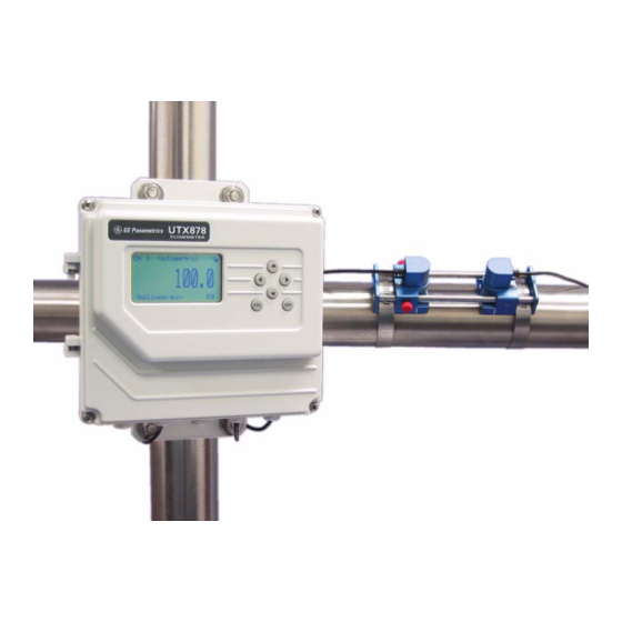
March 2004 Mounting the UTX878 The standard Model UTX878 electronics package is housed in a epoxy-coated aluminum weatherproof NEMA4X, IP67 enclosure Electronics Enclosure suitable for indoor or outdoor use. Figure 1-5 on page 1-11 shows the outline and installation drawing. Refer to Chapter 7, Specifications, for the mounting dimensions and the weight of this enclosure. -
Page 14: Wiring The Line Power
March 2004 Wiring the Line Power The Model UTX878 operates on 15-30 VDC loop power. The label on the side of the electronics enclosure lists the meter’s required line voltage and power rating. Be sure to connect the meter only to the specified line voltage and with a shielded cable. -
Page 15: Installing The Transducers
March 2004 Installing the The transducers that have been specially designed for use with the UTX878 are available in two models: 4 MHz for 1/2 to 2 in. pipes and Transducers 2 MHz for 2 to 8 in., and typically support 2-traverse applications. The preattached cables come in lengths from 6 to 100 ft. -
Page 16: Installing The Transducers On The Pipe
March 2004 Installing the Note: Some pipe preparation may be required before securing the transducers to the pipe. Remove any paint or coating from the Transducers on the Pipe surface in contact with the transducers. A flat, smooth surface is ideal. 1. -
Page 17: Wiring The Transducers
March 2004 Wiring the Transducers Follow the instructions on page 1-4 before wiring the transducers. !WARNING! Before connecting the transducers, discharge any static buildup by shorting the twisted pairs of the transducer cables to the metal shield on the cable connector. -
Page 18: Wiring The Rs232 Serial Port
Note: Signal names that imply direction (e.g., transmit and receive) are named from the point of view of the DTE device (the GE Panametrics meter is usually considered the DTE device). When the RS232 standard is strictly followed, these signals are labeled with the same name and pin # on the DCE device side as well. -
Page 19: What's Next
March 2004 Wiring the RS232 Serial 3. Feed the flying leads end of the cable through the conduit hole and wire the leads to the COMMUNICATION terminal block (TB4) Port (cont.) as shown in Figure 1-7 on page 1-13. Connect the other end of the cable to the ANSI terminal or personal computer, and secure the cable clamp. - Page 20 March 2004 Installation 1-11...
- Page 21 March 2004 Installation 1-12...
- Page 22 March 2004 Installation 1-13...
- Page 23 Chapter 2...
- Page 24 Programming Site Data Introduction ......... . .2-1 Activating a Channel/Path (Status).
-
Page 25: Introduction
March 2004 Introduction The Model UTX878 flow transmitter includes a User Program that provides access to the various programmable features of the instrument.This chapter describes step-by-step programming instructions using the internal keypad, shown below in Figure 2-1. Ch1 Volumetric 100.00 Gallons/min Figure 2-1: A UTX878 Display and Keypad Refer to the appropriate section for a discussion of the following... -
Page 26: Unlocking And Locking The Utx878
March 2004 Unlocking and Locking To prevent unauthorized tampering with either the display or the user program, the UTX878 offers a pair of security codes. Once you have the UTX878 set the security level, an operator requires one of these codes to change either the display (Prog Lock) or the display and the user program (Full Lock). -
Page 27: Locking The Utx878
March 2004 Locking the UTX878 You can access the security level in two ways. From the display screen: 1. Press the [ ] key three times, until the lock in the upper right corner is highlighted. 2. Press [ENT], and proceed to step 4 below. From the User Program: 1. -
Page 28: Activating A Channel/Path (Status)
March 2004 Activating a Channel/ In the Status submenu of the PROG menu, you can activate or deactivate a channel/path. While the channel/path should be activated Path (Status) when you receive your unit, you should verify that the channel/path is active before you begin programming. - Page 29 March 2004 What’s Next? After completing the above steps, the user program returns to the PROG menu. Do one of the following: • To enter transducer data, press the [ ] key to highlight the Transducer listing and press [ENT]. •...
-
Page 30: Entering Transducer Parameters
March 2004 Entering Transducer The Transducer submenu enables you to enter parameters for preprogrammed or special clamp-on transducers. Remember to Parameters record all programmed data in Appendix C, Data Records. Note: If you have programmed the Status submenu, proceed directly to Step 4. -
Page 31: Other Transducers
2. The meter next asks for the Time Delay (Tw). Scroll to the Tw option and press [ENT]. Then use the arrow keys to enter the time provided by GE Panametrics (in microseconds), and press [ENT]. 3. The next parameter is the Wedge Angle, the angle of the transducer’s ultrasonic transmission in the transducer wedge. -
Page 32: Entering Pipe Parameters
March 2004 Entering Pipe In the Pipe submenu, you can specify preprogrammed or special pipe parameters. While following the programming instructions, refer to Parameters Figure A-1 on page A-1 of Appendix A, Menu Maps. Remember to record all programmed data in Appendix C, Data Records. Note: If you are in the PROG menu, proceed directly to Step 4. - Page 33 March 2004 Entering the Pipe Table 2-1: Preprogrammed Pipe Materials Material (cont.) Pipe Material Category Specific Material Al - Aluminum Rolled or None Brass None Cu - Copper Annealed, Rolled or None CuNi - Copper/Nickel 70% Cu 30% Ni or 90% Cu 10% Ni Glass Pyrex, Flint, or Crown Gold...
- Page 34 March 2004 Entering the Pipe 6. If you have selected certain materials (such as carbon or stainless steel, cast iron, PVC and CPVC), the UTX878 offers the option of Material (cont.) entering the pipe dimensions by a standardized schedule. (This option does not appear unless you have selected one of these materials;...
-
Page 35: Entering Pipe Lining Data
Glass (Pyrex) Asbestos Cement Mortar Rubber Teflon Note: If your pipe lining is not on the drop-down list, consult GE Panametrics for further information. What’s Next? You have finished entering data in the Pipe submenu. Do one of the following: •... -
Page 36: Entering Fluid Data
March 2004 Entering Fluid Data The Fluid submenu allows you to specify the fluid you are measuring, as well as the Reynolds Correction factor and tracking windows. While following the programming instructions, refer to Figure A-1 on page A-1 of Appendix A, Menu Maps. Remember to record all programmed data in Appendix C, Data Records. -
Page 37: Entering Reynolds Correction Data
March 2004 Entering Fluid Data 8. The menu now varies, depending on your selections in steps 6 and 7. (cont.) • If you have selected Preprogrammed fluids, the UTX878 supplies a list of preprogrammed fluids. As shown in Table 2-3 on the next page, the list varies, depending on whether you have selected normal or tracking window fluid types. - Page 38 March 2004 Entering Reynolds 3. The menu varies, depending on your selection in Step 2. Correction Data (cont.) • If you select Off, no further choices are available. • If you select Single, the UTX878 will select and automatically display the Kinematic Viscosity. To change the value, press [ENT]. Use the arrow keys to change the value (available in document #914-004, Sound Speeds and Pipe Size Data), and press [ENT].
-
Page 39: Entering Path Data
March 2004 Entering Path Data In the Path submenu, you can specify and check the path taken by the transducer signal. Remember to record all programmed data in Appendix C, Data Records. Note: If you are in the PROG menu, proceed directly to Step 4. If you scroll to a different option, press [ENT] twice to select that option (once to enter and again to confirm the selection). -
Page 40: Entering Signal Parameters
Entering Signal In the Signal submenu, you can set parameters that affect the transducer signal: Parameters Caution! The SIGNAL default settings are suitable for most applications. Consult GE Panametrics before changing any of these applications. • Delta-T Offset • Zero Cutoff •... - Page 41 Note: Do not change the peak detection method or values unless recommended by GE Panametrics. a. Press [ENT]. The screen shows the two display options, Peak and Threshold. Scroll to the desired option, and press [ENT].
-
Page 42: Entering The Meter Correction (K) Factor
March 2004 Entering the Meter With the K Factor submenu, you can calibrate or adjust the UTX878 readings to another flow reference. While following the programming Correction (K) Factor instructions, refer to Figure A-1 on page A-1 of Appendix A, Menu Maps.To enter K Factor data: Note: If you are in the PROG menu, proceed directly to Step 4. -
Page 43: Entering Error Limits
March 2004 Entering Error Limits The Error Limits option enables you to set limits for an incoming signal. When the signal falls outside the programmed limits, an error indication appears on the display screen. To set error limits, follow the steps below. Note: If you are in the PROG menu, proceed directly to Step 4. -
Page 44: What's Next
March 2004 Entering Error Limits 12.The final prompt asks for the acceleration limit for detecting cycle skipping. The E6: ACCELERATION error message appears if the (cont.) velocity changes by more than this limit from one reading to the next. Press [ENT]. Use the arrow keys to change the value and press [ENT]. - Page 45 Chapter 3...
- Page 46 Displaying Data Introduction ......... . .3-1 Setting Up the Display .
-
Page 47: Introduction
March 2004 Introduction The Model UTX878 flow transmitter includes a Liquid Crystal Display (LCD) that can display up to two variables simultaneously. Users can change the number of variables, the displayed measurements and units, and the contrast level of the LCD. Setting Up the Display You can configure either of two channels for your particular requirements. -
Page 48: Changing The Channel
March 2004 Changing the Channel Note: This option is available only for 2-channel versions of the UTX878. The first parameter on the screen in the upper left is the Channel Number. You can change the display to show either of the two channels, or the average, sum or difference of the channels. -
Page 49: Adjusting The Numeric Display Format
March 2004 Adjusting the Numeric When you highlight the numeric display, you can control both its positioning and the number of decimal places displayed to the right of Display Format the decimal point. 1. Use the [ ] or [ ] key to highlight the numeric display, and press [ENT]. -
Page 50: Interpreting The Error Message
March 2004 Interpreting the Error The parameter in the lower right corner, represented by E and a number (E1, E2, etc.) is an error message that signals a particular Message problem with the measurement. To access an explanation of the error, use the [ ] or [ ] key to highlight the error code and press [ENT]. -
Page 51: Setting Screen Contrast
March 2004 Setting Screen For viewer convenience, you can reset the contrast level of the display screen. To change the contrast: Contrast 1. Press [ESC]. The UTX878 enters the User Program. 2. Press the [ ] key until DISP is bracketed in the upper left corner. 3. - Page 52 Chapter 4...
- Page 53 Configuring Meter Data Introduction ......... . .4-1 Entering Global Units.
-
Page 54: Introduction
March 2004 Introduction The CONFIG menu in the UTX878 User Program enables you to set global parameters for the meter that suit your individual preferences. The available parameters include: • Metric or English units • 4-20 Loop Settings (low and high values) •... -
Page 55: Entering Base (Zero) And Span Output Values
March 2004 Entering Base (Zero) The 4-20 Loop submenu enables you to enter the information needed to set up output parameters: unit type, base (zero) and span values, and Span Output and error handling. To enter data in the 4-20 Loop submenu: Values 1. -
Page 56: Entering Base And Span Values
March 2004 Entering Base and Span 1. In the Loop option, press [ ] and [ENT] to enter the Base option. Values 2. The Base window opens. Use the arrow keys to enter the desired base (4 mA) value for the analog output, and press [ENT]. 3. - Page 57 March 2004 Entering Error Handling Table 4-2: Error Options and Responses (cont.) for a 2-Channel/Path Meter Totalizer Response When Error Handling is When Display LO, HI, HH, LL, Measuring Response HOLD Value CH1 or CH2 Holds last Holds last “good” Stops “good”...
-
Page 58: Entering Rs232 Communication Settings
March 2004 Entering RS232 With the Communication submenu, you can set the parameters by which the UTX878 communicates to a PC or terminal over the RS232 Communication interface. You can set the Node ID as well as the baud rate, parity, Settings stop bits and data bits. -
Page 59: Resetting Forward And Reverse Totals
March 2004 Resetting Forward and On occasion, you may need to clear and reset the forward and reverse totals computed by the Forward and Reverse Totalizers. To reset the Reverse Totals totals: 1. Press [ESC]. The UTX878 enters the User Program. 2. - Page 60 Chapter 5...
- Page 61 Calibration Introduction ......... . .5-1 Updating UTX878 Instrument Software .
-
Page 62: Introduction
March 2004 Introduction In the CALIB menu, you can calibrate and trim the analog outputs and inputs and check other meter functions. This chapter also covers updating UTX878 software over the RS232 interface. Before performing calibration of the UTX878, be sure the following equipment is available: •... -
Page 63: Checking The Meter Software
Press the [ ] key until FACTORY is highlighted. Scroll to the Versions option and press [ENT]. c. Press [ENT] again to enter Main. The display should appear similar to Figure 5-1 below. 4 GE PANAMETRICS S/N: A000000 PCI: P000000 b: BOOT.XXX.X p: BETAX.XXX.X... -
Page 64: Trimming 4-20 Ma Via The Keypad
March 2004 Trimming 4-20 mA via 1. In the User Program, scroll to CAL with 4-20 Loop highlighted. Press [ENT]. the Keypad 2. Scroll to Mode and press [ENT]. In the Mode window, scroll to Test[Trim] and press [ENT]. 3. Return to the Loop window, and scroll to Percent. 4. - Page 65 Chapter 6...
- Page 66 Error Codes and Diagnostics Introduction ......... . .6-1 Error Codes.
-
Page 67: Introduction
March 2004 Introduction The Model UTX878 flow transmitter is a reliable, easy to maintain instrument. When properly installed and operated, as described in Chapter 1, Installation, the meter provides accurate flow rate measurements with minimal user intervention. However, if a problem should arise with the electronics enclosure or transducers, this chapter explains how to troubleshoot the Model UTX878. -
Page 68: E2: Sound Speed Error
March 2004 E2: Sound Speed Error Problem: The sound speed exceeds the limits programmed in the Error Limits option of the User Program. Cause: The error may be caused by incorrect programming, poor flow conditions or poor transducer orientation. Action: Compare the measured sound speed to tabulated nominal values for the process fluid and correct any programming errors. -
Page 69: E6: Cycle Skip, Accel
The channel has been turned off. Action: Enter the PROGRAM menu and enable the channel (see page 2-4). E31: Invalid Calibration Problem: The calibration is invalid. Cause: Improper calibration for the application has been entered. Action: Consult GE Panametrics. Error Codes and Diagnostics... -
Page 70: Displaying Diagnostic Parameters
March 2004 Displaying Diagnostic The Model UTX878 offers built-in Diagnostic Parameters to aid in the troubleshooting of transducer and/or electrical problems. To Parameters access these parameters, do the following: 1. From the display screen, press [ESC]. Note: If the display screen is locked, you will need to enter [ESC], [ENT], [ESC] and the security code. - Page 71 March 2004 Table 6-1: Available Diagnostic Parameters Option Bar Description Good ≤1 nsec Delta-T[ns] Displays the transit time difference >1 nsec between the upstream and downstream signals. Displays the value for the signal ampli- Amp Up 24 ± 5 <19 or >29 tude of the upstream transducer.
-
Page 72: Fluid And Pipe Problems
Read the following sections carefully to determine if the problem is indeed related to the fluid or the pipe. If the instructions in this section fail to resolve the problem, contact GE Panametrics for assistance. Fluid Problems Most fluid-related problems result from a failure to observe the flowmeter system installation instructions, as described in Chapter 1, Installation. -
Page 73: Pipe Problems
March 2004 Pipe Problems Pipe-related problems may result either from a failure to observe the installation instructions, as described in Chapter 1, Installation, or from improper programming of the meter. By far, the most common pipe problems are the following: 1. -
Page 74: Transducer Problems
To resolve a cycle skip, recouple both transducers with proper couplant. Check your couplant for temperature ranges. In addition, make sure the pipe wall is free of paint and rust. Contact GE Panametrics if you cannot solve a transducer-related problem. Error Codes and Diagnostics... - Page 75 Chapter 7...
-
Page 76: Specifications
Specifications General Specifications........7-1 Electrical Specifications ....... . .7-2 Transducer Specifications. -
Page 77: General Specifications
March 2004 General Specifications The general specifications for the Model UTX878 flow transmitter are divided into the following categories: Hardware Configuration Channel Options: Standard: 1-Channel/Path Optional: 2-Channel/Path (for 2-path averaging). Enclosure: Epoxy-coated aluminum, weatherproof, NEMA 4X, IP67 Dimensions: Weight 3.9 lb (2 kg) Size (h x w x d) 8.8 x 8.2 x 3.6 in. -
Page 78: Electrical Specifications
March 2004 Electrical The electrical specifications for the Model UTX878 flow transmitter are divided into the following categories: Specifications Power Requirements 15-30 VDC loop powered, 0.66 W max Output Drive Capability: × ] Rc Max. load (ohms) PSV 15 – –... -
Page 79: Transducer Specifications
Fixture with stainless steel strap. Pipe Size and Materials Clamp-on Transducers Pipe Materials: Can clamp to all metals and most plastics. (Consult GE Panametrics for concrete, composite materials and highly corroded or lined pipes.) Pipe Sizes: 0.5 to 8 in. (12 mm to 200 mm) Pipe Wall Thickness: Up to 3 in. - Page 80 Appendix A...
-
Page 81: Appendix A: Menu Maps
Menu Maps The UTX878 PROG Menu....... . A-1 The UTX878 CONFIG Menu ......A-2 The UTX878 DISP, CAL, USER, SERVICE and FACTORY Menus A-3... - Page 82 March 2004 Press [ESC] [ENT] [ESC] ( + passcode if locked) (Continued on Figure A-2.) PROG 2-Path Ave. Status Transducer Pipe Fluid Path Signal K Factor Error Limits Min Signal Delta T Offset Clamp-on Lining Table Max Signal Material Single Zero Cutoff Min Vel Traverses...
- Page 83 March 2004 Press [ESC] [ENT] [ESC] ( + passcode if locked) (Continued in Figure A-3.) (Continued from Figure A-1.) CONFIG Reset Totals Units 4-20 Loop Communication English Metric Node ID RS232 Units Error Level Base Span Status Ch 2 DIFF Ch 1 Reset Fwd Reset Rev...
- Page 84 March 2004 Press [ESC] [ENT] [ESC] ( + passcode if locked) (Continued from Figure A-2.) USER SERVICE DISP FACTORY Set Security Voltage Adjustment Default Upgrade Versions Contrast Views UnLocked Contrast % FullLocked ProgLocked 4-20 Loop Internal Cal Base Span Percent Mode Base Value Span Value Test Test/Trim Normal...
- Page 85 Appendix B...
-
Page 86: Appendix B: Ce Mark Compliance
CE Mark Compliance Introduction ......... . B-1 EMC Compliance . -
Page 87: Emc Compliance
March 2004 Introduction For CE Mark compliance, the Model UTX878 flow transmitter must meet the EMC directive. IMPORTANT: CE Mark compliance is required only for units intended for use in EEC countries. EMC Compliance In addition to the standard wiring requirements, the electrical connections must be shielded and grounded as in Table B-1 below for EMC compliance. - Page 88 Appendix C...
-
Page 89: Appendix C: Data Records
Data Records Site Data ..........C-1... -
Page 90: Site Data
March 2004 Site Data After the Model UTX878 flow transmitter has been installed, specific site data must be entered via the User Program, prior to operation. Record that information in Table C-1 below. Table C-1: Site Data General Information Model # Serial # Software Vers. - Page 91 March 2004 Table C-1: Site Data (cont.) Channelx-Error Limits Channel 1 Channel 2 (if applicable) Min. Signal Min. Signal Max. Signal Max. Signal Min.Velocity Min.Velocity Max. Velocity Max. Velocity Min. Amplitude Min. Amplitude Max. Amplitude Max. Amplitude Soundspeed Soundspeed Acceleration Acceleration Channelx-Signal Channel 1...
- Page 92 March 2004 Table C-1: Site Data (cont.) Channelx- KFACTOR Table (cont.) Channelx- Reynolds Number Table Channel 1 Channel 2 (if applicable) Reynolds Row # Units K-Factor Row # Units Data Records...
- Page 93 Appendix D...
-
Page 94: Appendix D: Service Record
Service Record Introduction ......... . D-1 Data Entry . -
Page 95: Data Entry
March 2004 Introduction Whenever any service procedure is performed on the Model UTX878 flow transmitter, the details of the service should be recorded in this appendix. An accurate service history of the meter can prove very helpful in troubleshooting any future problems. Data Entry Record complete and detailed service data for the Model UTX878 in Table D-1 below. - Page 96 March 2004 Table D-1: Service Record (cont.) Date Description of Service Performed By Service Record...
-
Page 97: Diagnostic Parameters
March 2004 Diagnostic Parameters After a successful initial installation of the Model UTX868 and whenever any system malfunction is noticed, the values for the diagnostic parameters should be entered in Table D-2 below. Table D-2: Diagnostic Parameters Parameter Initial Current Parameter Initial Current... - Page 98 March 2004 Index Symbols #Errors ......6-5 Data Bits ......4-5 Data Record .
- Page 99 March 2004 Index (cont.) E0 ........6-1 FACTORY Menu.
- Page 100 March 2004 Index (cont.) Line Power, Wiring ....1-5 Parity ....... .4-5 Lining Soundspeed.
- Page 101 March 2004 Index (cont.) Schedule for Pipe Materials ... . . 2-10 T Up....... . D-3 Screen Views,Setting Number of .
- Page 102 March 2004 Index (cont.) Units (for Output),Entering ....4-2 UP +- Peak ..... . . 6-5, D-3 UP Amp Disc .
- Page 103 WORLDWIDE OFFICES MAIN OFFICES: GE PANAMETRICS INTERNATIONAL OFFICES: Australia Japan GE Panametrics P.O. Box 234 2F, Sumitomo Bldg. 221 Crescent St., Suite 1 Gymea N.S.W. 2227 5-41-10, Koishikawa, Bunkyo-Ku Waltham, MA 02453-3497 Australia Tokyo 112-0002 Telephone 61 (02) 9525 4055...
Need help?
Do you have a question about the UTX878 Ultrasonic and is the answer not in the manual?
Questions and answers