
Related Manuals for GE DigitalFlow XMT868i


Summary of Contents for GE DigitalFlow XMT868i
- Page 1 Measurement & Control Flow DigitalFlow™ XMT868i Ultrasonic Flow Transmitter for Liquids (1 & 2-Channel) Startup Guide 910-171U Rev. H February 2017...
- Page 3 DigitalFlow™ XMT868i Ultrasonic Flow Transmitter for Liquids (1 & 2-Channel) Startup Guide 910-171U Rev. H February 2017 www.gemeasurement.com ©2016 General Electric Company. All rights reserved. Technical content subject to change without notice.
- Page 4 [no content intended for this page]...
- Page 5 Preface Information Paragraphs Note: These paragraphs provide information that provides a deeper understanding of the situation, but is not essential to the proper completion of the instructions. IMPORTANT: These paragraphs provide information that emphasizes instructions that are essential to proper setup of the equipment.
- Page 6 Environmental Compliance Waste Electrical and Electronic Equipment (WEEE) Directive GE Measurement & Control is an active participant in Europe’s Waste Electrical and Electronic Equipment (WEEE) take-back initiative, directive 2012/19/EU. The equipment that you bought has required the extraction and use of natural resources for its production. It may contain hazardous substances that could impact health and the environment.
-
Page 7: Table Of Contents
Contents Chapter 1. Installation 1.1 Introduction ................... . 1 1.2 Unpacking . - Page 8 Contents Chapter 4. Specifications 4.1 General ....................59 4.1.1 Hardware Configuration.
-
Page 9: Chapter 1. Installation
1.1 Introduction To ensure safe and reliable operation of the Model XMT868i Flow Meter, the system must be installed in accordance with the guidelines established by GE engineers. Those guidelines, explained in detail in this chapter, include the following topics: •... -
Page 10: Site Considerations
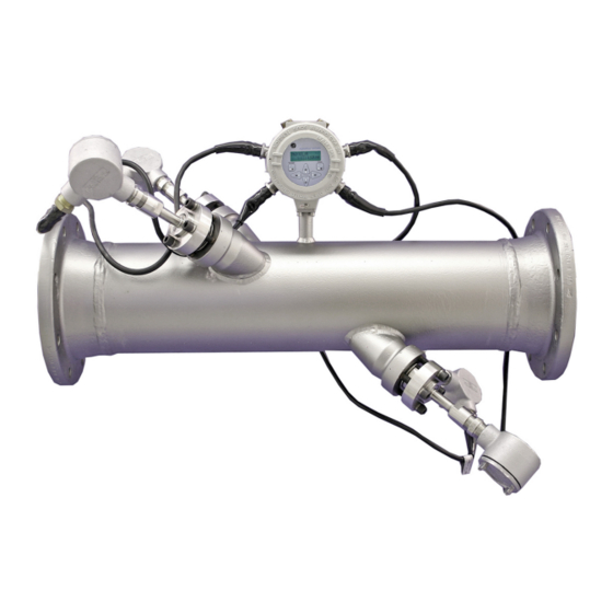
Chapter 1. Installation 1.3 Site Considerations Because the relative location of the flowcell and the electronics enclosure is important, use the guidelines in this section to plan the XMT868i installation. Figure 1 below shows a typical installation. Figure 1: A Typical Model XMT868i System 1.3.1 Electronics Enclosure Location The standard Model XMT868i electronics enclosure is a powder-coated, cast-aluminum, Type-7/4X explosion-proof enclosure, and an optional stainless-steel enclosure is available. -
Page 11: Transducer Location
Locate the electronics enclosure as close as possible to the flowcell/transducers, preferably directly on the flowcell. However, GE can supply transducer cables up to 1,000 ft (300 m) in length for remote location of the electronics enclosure. If longer cables are required, consult the factory for assistance. -
Page 12: Installing Temperature Transmitters
Chapter 1. Installation 1.5 Installing Temperature Transmitters Optional temperature transmitters may be installed as part of the flowcell, near the ultrasonic transducer ports. Be sure to observe the siting requirements given earlier in this chapter. These transmitters should send a 0/4-20 mA signal to the Model XMT868i. -
Page 13: Mounting The Xmt868I Electronics Enclosure
Chapter 1. Installation 1.6 Mounting the XMT868i Electronics Enclosure The standard model XMT868i electronics package is housed in a Type-4X weather-resistant enclosure suitable for indoor or outdoor use. Refer to Figure 8 on page 21 for the mounting dimensions and the weight of this enclosure. The Model XMT868i electronics enclosure is fitted with a mounting boss that has a single 3/4”... -
Page 14: Wiring The Line Power
Chapter 1. Installation Making Electrical Connections (cont.) Power Connections Option Card Connections Set Screw Slots Label Inside View Outside View Figure 3: Rear Cover with Connection Labels 1.7.1 Wiring the Line Power The Model XMT868i may be ordered for operation with power inputs of 100-120 VAC, 220-240 VAC, or 12-28 VDC. The label on the side of the electronics enclosure lists the meter’s required line voltage and power rating. - Page 15 Chapter 1. Installation 1.7.1 Wiring the Line Power (cont.) 1. Prepare the line power leads by trimming the line and neutral AC power leads (or the positive and negative DC power leads) to a length 0.5 in. (1 cm) shorter than the ground lead. This ensures that the ground lead is the last to detach if the power cable is forcibly disconnected from the meter.
-
Page 16: Wiring Transducers
Chapter 1. Installation 1.7.2 Wiring Transducers Before wiring the XMT868i transducers, complete the following steps: 1. Disconnect the main power from the electronics enclosure. 2. Remove the rear cover and install all required cable clamps. WARNING! Before connecting the transducers, take them to a safe area and discharge any static buildup by shorting the center conductor of the transducer cables to the metal shield on the cable connector. -
Page 17: Wiring Standard 0/4-20 Ma Analog Outputs
The Model XMT868i flow transmitter is equipped with a built-in serial communications port. The standard port is an RS232 interface, but an optional RS485 interface is available upon request. Proceed to the appropriate sub-section for wiring instructions. For more information on serial communications refer to the EIA-RS Serial Communications manual (GE document 916-054). DigitalFlow™ XMT868i Startup Guide... - Page 18 Note: Signal names that imply direction (e.g., transmit and receive) are named from the point of view of the DTE device (the GE meter is usually considered the DTE device). When the RS232 standard is strictly followed, these signals are labeled with the same name and pin # on the DCE device side as well. Unfortunately, the convention is not followed because the DTE and DCE side get confused.
- Page 19 Chapter 1. Installation 1.7.4b Wiring the RS485 Interface Use the optional RS485 serial port to network multiple XMT868i flow transmitters to a single computer terminal. As an option, the standard RS232 port on the XMT868i may be configured as a two-wire, half-duplex RS485 interface. The XMT868i must be configured at the factory for RS485 operation.
-
Page 20: Wiring Option Cards
Chapter 1. Installation 1.7.5 Wiring Option Cards The XMT868i can accommodate one option card in and one option card in . The following types of option Slot 1 Slot 2 cards are available only in the combinations listed in Table 22 on page 69: •... - Page 21 Chapter 1. Installation 1.7.5b Wiring an Alarms Option Card Each alarms option card includes two or four general-purpose Form C relays (designated as A, B, C and D). The maximum electrical ratings for the relays are listed in Chapter 4, Specifications. Each of the alarm relays can be wired as either Normally Open (NO) or Normally Closed (NC).
- Page 22 Chapter 1. Installation 1.7.5c Wiring a 0/4-20 mA Analog Inputs Option Card This option card includes two or four isolated 0/4-20 mA analog inputs (designated as A, B, C and D), each of which includes a 24 VDC power supply for loop-powered transmitters. Either input may be used to process the temperature signal, while the other input is used to process the pressure signal.
- Page 23 Chapter 1. Installation 1.7.5d Wiring a Totalizer and Frequency Output Option Card Each totalizer and frequency output option card provides two or four outputs (designated as , and A, B, C Wire this option card in accordance with the connections shown on the label in the rear cover (see Figure 3 on page 6 and Figure 11 on page 24).
- Page 24 Chapter 1. Installation 1.7.5e Wiring an RTD Inputs Option Card The Model XMT868i RTD (Resistance Temperature Device) inputs option card provides two direct RTD inputs (designated as A and B). Each RTD input requires three wires, and should be connected as shown on the label in the rear cover (see Figure 3 on page 6 and Figure 11 on page 24).
- Page 25 Slot 2. The RS485 standard allows up to 32 nodes (drivers and receivers) on one multi-drop network, at distances up to 4,000 ft (1,200 m). GE recommends using 24-gauge (24 AWG) twisted-pair wire with a characteristic impedance of 120 ohms and 120-ohm termination at each end of the communications line.
- Page 26 Chapter 1. Installation 1.7.5i Wiring the MODBUS/TCP Interface Customers can also use a modified XMT868i that provides a MODBUS/TCP interface to communicate to an internal network. An optional MODBUS/TCP card with a unique MAC (IP) address (installed only in slot 2) includes an RJ45 connector.
- Page 27 Chapter 1. Installation 1.7.5k Wiring the Foundation Fieldbus Interface To connect the Foundation Fieldbus interface to the XMT868i, make the network connections at J8, pins 1 and 2, as shown in drawing Y of Figure 12 on page 25. As an option, you can connect a shield to J8 pin 3, depending on the network wiring.
- Page 28 Chapter 1. Installation [no content intended for this page] DigitalFlow™ XMT868i Startup Guide...
- Page 29 Chapter 1. Installation Ø6.10 (155) 51° 7 PLCS 2.06 (52) 3/4" NPTF 7 PLCS 3.86 (98) 3/4" NPTF 7 PLCS 8.20 (208) DETAIL A 0.52 (13) VIEW A-A 0.28 (7) 1.00 (25) 0.25 (6) 1.50 (38) NOTES: 1. ALL DIMENSIONS ARE REFERENCE. 2.
- Page 30 Chapter 1. Installation .135 Ø6.10 (155) .135 R .410 2.06 (52) 51° 7 PLCS .270 .205 3.86 DETAIL C (98) 8 PLACES 3/4" NPTF 8.20 7 PLCS (208) 1.250 5.00 1.250 DETAIL A 2.375" PIPE REF ONLY 1.250 0.52 (13) .625 SEE DETAIL C 1.00...
- Page 31 Chapter 1. Installation J2 - INPUT/OUTPUT CONNECTIONS* For compliance with the European Union's Low Voltage Directive NOTE: Pin # (2006/95/EC), this unit requires an external power disconnect device Designation I/O1 I/O2 I/O3 I/O4 I/O5 I/O6 I/O7 I/O8 I/O9 I/O10 I/O11 I/O12 such as a switch or circuit breaker.
- Page 32 Chapter 1. Installation -01 (AA,HH) -02 (FF,TT,FT,CT,CF) -03 (FO,TO,CO) -04 (FA,FH,TA,TH,CA,CH) -05 (CI,TI,FI) -06 (CR,FR,TR) Pin 1 Pin 1 Pin 1 Pin 1 Pin 1 Pin 1 -07 (CIR) -08 (AI,HI) -09 (OI) -10 (OR) -11 (AR,HR) -12 (II) Pin 1 Pin 1 Pin 1 Pin 1...
- Page 33 Chapter 1. Installation ETHERNET ETHERNET (RJ45) (RJ45) ETHERNET FOUNDATION FIELDBUS MODBUS/TCP Terminal Block Connector Terminal Block Connector Terminal Block Connector DigitalFlow™ XMT868i Startup Guide...
- Page 34 Chapter 1. Installation [no content intended for this page] DigitalFlow™ XMT868i Startup Guide...
-
Page 35: Chapter 2. Initial Setup
Create custom templates for displaying text, graph and log data • Interface with multiple GE instruments. This chapter focuses on programming using the magnetic keypad. For information on programming the XMT868i using PanaView, refer to Appendix C of the Programming Manual. -
Page 36: Xmt868I Enclosure Keypad Program
Chapter 2. Initial Setup 2.2 XMT868i Enclosure Keypad Program Along with the 2-line, 16-character LCD, the XMT868i includes a 6-key magnetic keypad. The decal cutout for each key contains a hall effect sensor, pushbutton switch and visible red LED. The magnetic wand used to activate a magnetic key is found attached to the meter chassis below the front panel. -
Page 37: Entering Data In The Global Menu
Chapter 2. Initial Setup XMT868i Enclosure Keypad Program (cont.) The meter then starts to display measured parameters. 10.00 Ft/s To enter the Keypad Program, press the key, followed by the key, and the key again. Each [Escape] [Enter] [Escape] successive key must be entered within 10 seconds of the prior key. As a guide in following the programming instructions in this chapter, the relevant portions of the Model XMT868i menu map have been reproduced in Figure 14 on page 45 and Figure 15 on page 46. - Page 38 Chapter 2. Initial Setup 2.3.1a Volumetric Units . Table 5 below lists the 6. Scroll to the desired Volumetric Units for the flow rate display and press [Enter] available volumetric units. Table 5: Available Volumetric Units English Metric GAL/S = gallons/second L/S = Liter/sec GAL/M = gallons/minute L/M = Liter/min...
- Page 39 Chapter 2. Initial Setup 2.3.1b Totalizer Units 8. Scroll to the desired Totalizer Units for the totalized flow rate display (see Table 6 below), and press [Enter] Table 6: Totalizer Units English Metric GAL = Gallons L = Liters MGAL = mega gallons ML = Megaliters ft^3 = Cubic feet m^3 = Cubic meters...
- Page 40 Chapter 2. Initial Setup 2.3.1c Programming Mass Flow Data 1. Scroll to the desired Mass Flow Units for flow rate display (see Table 7 below), and press [Enter] Table 7: Available Mass Flow Units English Metric LB = Pounds KG = Kilograms KLB = KiloPounds (Thousands of Pounds) Tonne = Metric Tons (1000 KG) MMLB = MegaPounds TONS (2000 LB)
- Page 41 Chapter 2. Initial Setup 2.3.1d Programming the Energy Option 1. Scroll to the desired Power Units (see Table 8 below) and press [Enter] Table 8: Available Power Units English Metric kBTUh = Thousands of BTUs/hour kCALs = Kilocalories/second MMBTU = Millions of BTUs/hour kCALm = Kilocalories/minute kW = Kilowatt kCALh = Kilocalories/hour...
-
Page 42: Entering Data In The Channel Menu
Chapter 2. Initial Setup 2.4 Entering Data in the Channel Menu menu is used to enter data specific to each channel. Refer to Figure 14 on page 45 and remember to Channel record all programming data in Appendix B, Data Records. Note: In this manual, only the programming of Channel 1 will be described. -
Page 43: Entering Data In The Channel System Option
Chapter 2. Initial Setup 2.4.2 Entering Data in the Channel System Option 1. From the menu, scroll to the option and press Channel PROGRAM SYSTM [Enter] 2. The first prompt asks for the Channel Label.Use the four arrow keys to enter the desired label (in any numeric or text combination up to three characters) in the right pane, and press [Enter] 3. - Page 44 Chapter 2. Initial Setup 2.4.2 Entering Data in the Channel System Option (cont.) 6. Scroll to the desired number of Vol Decimal Digits (digits to the right of the decimal point) in the volumetric flow display, and press [Enter] 7. Scroll to the desired Totalizer Units for the totalized flow rate display (see Table 11 below), and press [Enter] Table 11: Totalizer Units English...
- Page 45 Chapter 2. Initial Setup 2.4.2a Programming the Mass Flow Option 1. Scroll to the desired Mass Flow Units for flow rate display (see Table 12 below), and press [Enter] Table 12: Available Mass Flow Units English Metric LB = Pounds Kilograms KLB = KiloPounds (Thousands of Pounds) Tonnes = Metric Tons (1000 KG) MMLB = MegaPounds...
- Page 46 Chapter 2. Initial Setup 2.4.2b Programming the Energy Option 1. Scroll to the desired Power Units (see Table 13 below) and press [Enter] Table 13: Available Power Units English Metric kBTUh = Thousands of kCALs = Kilocalories/second BTUs/hour MMBTU = Mega BTUs/hour kCALm = Kilocalories/minute kW = Kilowatt kCALh = Kilocalories/hour...
-
Page 47: Entering Pipe Parameters
The program first asks for the Wedge Type. Press the appropriate transducer type (Rayleigh clamp-on, shear clamp-on, or wetted). Note: GE will supply the information required for steps b through f with the transducers. b. Press the appropriate Frequency (from 500 kHz to 5 MHz). - Page 48 Plastic Nylon Polyethylene Polypropylene PVC (Polyvinyl Chloride), CPVC Acrylic OTHER Enter the soundspeed of the pipe material and press . If the soundspeed is unknown, [Enter] refer Sound Speeds and Pipe Size Data (GE document 914-004). DigitalFlow™ XMT868i Startup Guide...
- Page 49 Obtain the required information by measuring either the pipe outside diameter (OD) or circumference at the transducer installation site. The data may also be obtained from standard pipe size tables found in Sound Speeds and Pipe Size Data (GE document 914-004). Table 16: Available Pipe OD Units...
- Page 50 Chapter 2. Initial Setup 2.4.3f Tracking Windows 10. Press the appropriate choice to indicate whether you want Tracking Windows. These windows are used to detect the receive signal when you are unsure of the fluid sound speed. 2.4.3g Fluid Type 11.
- Page 51 Chapter 2. Initial Setup 2.4.3h Reynolds Correction 12. Scroll to the appropriate choice to indicate whether you want Reynolds Correction. • If Off is selected, enter the Calibration Factor and press [Enter] • If Activ is selected, the program asks for KV Input Selection. Scroll to SIGS (Signals), SOUND (Soundspeed) or STATC.
- Page 52 Chapter 2. Initial Setup [no content intended for this page] DigitalFlow™ XMT868i Startup Guide...
- Page 53 Chapter 2. Initial Setup [Esc] [Enter] [Esc] PROG RESET CALIB CONTRAST (* for 2-Channel meter only) CH2* GLOBL SYSTM COMM METER MESSAGE ACTIV SYSTM PIPE SETUP SYSTEM UNITS See Figure 2-3 SITE/CHANNEL LABEL SITE/CHANNEL MESSAGE METRC ENERGY OPTION Disabled* Transit 1-CHANNEL UNITS 2-CHANNEL UNITS VOLUMETRIC UNITS...
- Page 54 Chapter 2. Initial Setup [Esc] [Enter] [Esc] PROG RESET CALIB CONTRAST (* for 2-Channel meter only) CH2* GLOBL SYSTM COMM See Figure 2-2 ACTIV SYSTM PIPE SETUP See Figure 2-2 See Figure 2-2 TRANSDUCER NUMBER SPEC TRACKING WINDOWS? SPECIAL TRANSDUCER WEDGE TYPE RAYL SHEAR...
-
Page 55: Chapter 3. Operation
Chapter 3. Operation Chapter 3. Operation 3.1 Introduction See Chapter 1, Installation, and Chapter 2, Initial Setup, to prepare the Model XMT868i system for operation. When the meter is ready to take measurements, proceed with this chapter. The following specific topics are discussed: •... -
Page 56: Powering Up
Chapter 3. Operation 3.2 Powering Up Because the Model XMT868i does not have an ON/OFF switch, it will power up as soon as the connected power source is energized. Note: For compliance with the European Union’s Low Voltage Directive, this unit requires an external power disconnect device such as a switch or circuit breaker. -
Page 57: The Lcd Display
Chapter 3. Operation 3.3 The LCD Display The components of the LCD display are shown in Figure 16 below, along with a typical mass flow rate readout. Channel # Parameter CH1 VOL 4500 GAL/H XMT868i Flow Rate Units Figure 16: A Typical LCD Flow Rate Display The display screen includes the following information: •... -
Page 58: The Optional Panaview Display
Chapter 3. Operation 3.4 The Optional PanaView Display The components of the PanaView text display appear in Figure 17 below, along with a typical flow rate readout. Figure 17: A Typical PanaView Text Display Window The text display window includes the following information: •... -
Page 59: Taking Measurements
Chapter 3. Operation 3.5 Taking Measurements The Model XMT868i is capable of displaying several different variables in a variety of formats. However, this manual will only discuss the basic measurement displays using the LCD display or the PanaView display. Refer to Chapter 2, Displaying Data, in the Programming Manual for instructions on setting up alternate choices. - Page 60 Chapter 3. Operation 3.5.1 Programming the LCD (cont.) 8. Scroll to the desired Channel Option from the list in Table 19 below. Table 19: Channel Options Option Description Channel 1 Channel 2 CH1+CH2 CH1-CH2 (CH1+CH2)/2 9. For each channel, select the desired Measurement Parameter from the list in Table 20 below. Table 20: Output Measurement Options Option Bar Choice Description...
-
Page 61: Using The Lcd Display
Chapter 3. Operation Table 20: Output Measurement Options (cont.) Option Bar Choice Description Displays the signal quality for the upstream transducer. Qdown Displays the signal quality for the downstream transducer. AMPup Displays the value for the signal amplitude of the upstream transducer. AMPdn Displays the value for the signal amplitude of the downstream transducer. -
Page 62: Panaview Display
Chapter 3. Operation 3.5.3 PanaView Display Note: See Chapter 2, Initial Setup, in this manual and/or Chapter 1, Programming Site Data, in the Programming Manual for complete instructions on entering startup data using PanaView. Power up PanaView, establish communications with the XMT868i and enter the , as required startup parameters described in Chapter 2, Initial Setup. - Page 63 Chapter 3. Operation 3.5.3 PanaView Display (cont.) 4. From the expanded tree, double-click on the desired flow parameter to display it in the right pane of the window. 5. Before actual data values can be displayed in the text pane, activate one of the following data collection modes (see Figure 19 on page 54): •...
- Page 64 Chapter 3. Operation 3.5.3a Displaying Multiple Process Parameters The procedure for displaying a single process parameter in a text screen may be repeated to simultaneously display multiple process parameters. To do so, proceed as follows: 1. Display the first process parameter in a text screen, as described in the previous section. 2.
-
Page 65: Pausing Measurement
Chapter 3. Operation 3.5.3b Displaying Multiple Text Windows The procedures for displaying one or more process parameters in a single Text Display window may be repeated to open multiple Text Display windows. To do so, proceed as follows: 1. To open another Text Display window and display the desired process parameter(s) in the new window, repeat the steps in PanaView Display. - Page 66 Chapter 3. Operation 3.5.4a Procedure Options This Startup Guide is intended to provide only those instructions necessary to get the XMT868i installed and operating. By following the instructions in this chapter, the Model XMT868i can be set up to display the desired channel option and the desired measurement parameter, using either the LCD display or PanaView.
-
Page 67: General
Chapter 4. Specifications Chapter 4. Specifications 4.1 General The general specifications for the Model XMT868i flow transmitter are divided into the following categories. 4.1.1 Hardware Configuration Channel Options: Standard: 1 Channel Optional: 2 Channel (2 pipes or 2 paths per pipe) Mode Options: Transit-Time Package Options:... -
Page 68: Flow Accuracy (Velocity)
Chapter 4. Specifications 4.1.3 Flow Accuracy (Velocity) ±0.5% of reading (achievable with process calibration) Accuracy specifications assume a fully developed flow profile and a straight run of 10 pipe diameters upstream and 5 pipe diameters downstream. Typical Clamp-On Flow Accuracy (Velocity) Pipe Diameter (ID) >... -
Page 69: Electrical
Chapter 4. Specifications 4.2 Electrical The electrical specifications for the Model XMT868i flow transmitter are divided into the following categories. 4.2.1 Power Supply Options: Standard: 95 to 240 VAC, 50/60 Hz, ± 10% Optional: 12 to 28 VDC, ± 5% Power Consumption: 20 W maximum 4.2.2 Operating Modes... -
Page 70: Input/Output
General Purpose: 120 VAC, 28 VDC max., 5 A max., DC: 30 W max., AC: 60 VA max. Note: The above optional inputs/outputs are available only in specific combinations. Consult GE or see Table 22 on page 69 for details. -
Page 71: Additional Options
Chapter 4. Specifications 4.2.5 Additional Options PC-Interface Software: PanaView™ software option links the XMT868i to a PC. Software package includes CD and manual. 4.3 Transducer 4.3.1 Wetted Transducers Material: Standard: 316 Stainless Steel Optional (for isolating PanAdapta Plugs ): Hastelloy, Monel, Titanium, Duplex, CPVC, PVDF and others Process Connection: Standard: 1-in. -
Page 72: Clamp-On Transducers
Chapter 4. Specifications 4.3.2 Clamp-On Transducers Temperature Range: Standard: –40° to 300°F (–40° to 150°C) Optional (overall range): -310 to 572 F (-190 to 300 Mounting: Stainless steel chain or strap, welded or magnetic clamping fixtures Area Classifications: Standard: General-purpose Optional: Explosion proof: Class I, Div. -
Page 73: Pipe Size And Materials
Chapter 4. Specifications 4.4 Pipe Size and Materials 4.4.1 Wetted Transducers Materials: All metals and most plastics (Consult the factory for concrete, glass and cement.) Pipe Sizes: Transit-Time Mode: Inside diameter 1 to 200 in. 4.4.2 Clamp-on Transducers Materials: All metals and most plastics (Consult the factory for concrete, composite materials and highly corroded or lined pipes.) Pipe Sizes: Transit-Time Mode:... -
Page 74: Flowcell
Chapter 4. Specifications 4.5 Flowcell 4.5.1 Tilted Diameter Pipe Sizes: Standard: 2 to 200 in. (50 to 5,000 mm) Optional: >200 in. Material: Standard: Stainless steel; carbon steel; plastics; fiberglass Optional: Other metals, plastics, etc. Process Connection: Standard: Straight (welding); 150# flange; 300# flange Optional: MJ, Victaulic, RTJ flanged (cold tap). -
Page 75: Appendix A. Ce Mark Compliance
Appendix A. CE Mark Compliance Appendix A. CE Mark Compliance A.1 Introduction For CE Mark compliance, the Model XMT868i flow transmitter must be wired in accordance with the instructions in this appendix. CE Mark compliance is required for all units intended for use in EU countries. IMPORTANT: A.2 Wiring The Model XMT868i must be wired with the recommended cable, and all connections must be properly shielded and... - Page 76 Appendix A. CE Mark Compliance [no content intended for this page] DigitalFlow™ XMT868i Startup Guide...
-
Page 77: Appendix B. Data Records
Appendix B. Data Records Appendix B. Data Records B.1 Available Option Cards The XMT868i can accommodate one option card in Slot 1 and one in Slot 2. The available configurations are listed in Table 22 below. Table 22: Option Card Configurations Card #713- Slot # Configuration... -
Page 78: Option Cards Installed
Appendix B. Data Records B.2 Option Cards Installed Whenever an option card is installed or changed in the XMT868i flow transmitter, record the type of card and any additional setup information in the appropriate row of Table 23 below. Table 23: Option Cards Installed Slot # Type of Option Card Additional Setup Information... -
Page 79: Site Data
Appendix B. Data Records B.3 Site Data After the Model XMT868i flow transmitter has been installed, specific site data must be entered via the Keypad Program, prior to operation. Record that information in Table 24 below. Table 24: Site Data General Information Model # Serial #... - Page 80 Appendix B. Data Records Table 24: Site Data (cont.) CHANNELx-I/O Zero Cutoff Temp. Input Fixed ( Live Pipe/Transducer Parameters - PIPE Channel 1 Channel 2 (if applicable) Trans. Type SPEC Trans. Type SPEC Transducer # Transducer # Special Transducers Special Transducers Wedge Type Rayl Shear Wettd Wedge Type...
- Page 81 Appendix B. Data Records Table 24: Site Data (cont.) CHx-SETUP-ADVANCED FEATURES-KV/SS KV/SS (or C3) Pairs KV/SS (or C3) Pairs Sig. Strength/ Kinematic Sig. Strength/ Kinematic Soundspeed Viscosity Soundspeed Viscosity CHx-SETUP-ADVANCED FEATURES-MULTIK Custom Type CstV CstR CustomType CstV CstR K-Factor Table K-Factor Table K-Factor # Vel./Reynolds...
- Page 82 Appendix B. Data Records Table 24: Site Data (cont.) CHx-SETUP-ADVANCED FEATURES-MULTIK (cont.) K-Factor # Vel./Reynolds K Factor K-Factor # Vel./Reynolds K Factor DigitalFlow™ XMT868i Startup Guide...
-
Page 83: Appendix C. Measuring P And L Dimensions
Appendix C. Measuring P and L Dimensions Appendix C. Measuring P and L Dimensions C.1 Measuring P and L If you are using wetted transducers, the XMT868i requires you to enter the path length ( ) and the axial dimension ( where is the transducer face-to-face distance and is the axial projection of... - Page 84 Appendix C. Measuring P and L Dimensions Measuring P and L (cont.) Use Figure 23 below to properly measure the coupling length. Typically, the transducer face is positioned just outside the inside diameter (ID) of the pipe or slightly retracted inside the coupling. MA = 45°...
- Page 85 RETURN AUTHORIZATION NUMBER (RAN), and shipping instructions for the return of the instrument to a service center will be provided. 2. If GE Sensing instructs you to send your instrument to a service center, it must be shipped prepaid to the authorized repair station indicated in the shipping instructions.
- Page 86 Warranty [no content intended for this page] DigitalFlow™ XMT868i Startup Guide...
- Page 87 Index ....33 Energy Option, Programming ....... . 28 Enter Key .
- Page 88 Index ......2 Pressure Transmitter LVD Statement ....... . 4 Installing .
- Page 89 Index Terminal Block Wiring ..... . . 9 ..... . 67 Analog Outputs - I/O CE Mark Compliance .
- Page 90 Index [no content intended for this page] DigitalFlow™ XMT868i Startup Guide...
- Page 91 • Cable glands of an approved flameproof design are required. These must be installed according to the manufacturer’s instructions. Where the cable glands are provided by GE, the manufacturer’s instructions, as supplied, to GE, will be included in the documentation.
- Page 92 [no content intended for this page]...
- Page 93 Where products were initially assessed for compliance with the Essential Health and Safety Requirements of the ATEX Directive 94/9/EC using earlier harmonized standards, a subsequent review has determined that “technical knowledge” is unaffected by the current harmonized standards listed above. 16 June 2016 Issued Mr. Chris Frail Engineering Manager GE Measurement Solutions Billerica, MA U.S.A.
- Page 94 [no content intended for this page]...
- Page 96 Customer Support Centers U.S.A. The Boston Center 1100 Technology Park Drive Billerica, MA 01821 U.S.A. Tel: 800 833 9438 (toll-free) 978 437 1000 E-mail: sensing@ge.com Ireland Sensing House Shannon Free Zone East Shannon, County Clare Ireland Tel: +353 (0)61 470200 E-mail: gesensingsnnservices@ge.com An ISO 9001:2008 Certified Company www.gemeasurement.com/en/about-us/quality.html...
Need help?
Do you have a question about the DigitalFlow XMT868i and is the answer not in the manual?
Questions and answers