
Related Manuals for GE HygroPro


Summary of Contents for GE HygroPro
- Page 1 Measurement & Control Moisture HygroPro User’s Manual 916-099 Rev. D November 2012...
- Page 3 Measurement & Control HygroPro Moisture Transmitter User’s Manual 916-099 Rev. D November 2012 www.ge-mcs.com ©2012 General Electric Company. All rights reserved. Technical content subject to change without notice.
- Page 4 [no content intended for this page - proceed to next page]...
-
Page 5: Table Of Contents
2.3.3 Locking and Unlocking the Keypad ....33 2.3.4 Locking and Unlocking the Menus ....33 HygroPro User’s Manual Page iii... - Page 6 4.7 Certifications ........48 Page iv HygroPro User’s Manual...
-
Page 7: Chapter 1: Installation
IP67/Type 4X enclosure. The HygroPro transmitter uses an aluminum oxide moisture sensor, and it includes a temperature thermistor and a pressure transducer on a common mount for calculation of parameters such as: •... -
Page 8: Sample System Guidelines
Chapter 1: Installation 1.2 Sample System Guidelines The HygroPro transmitter can be installed in a sample system or directly in the process line. However, GE recommends that the unit be installed in a sample system to protect the probe from potentially damaging components in the process stream. - Page 9 If possible, use stainless steel for all wetted parts. • The HygroPro probe should be oriented perpendicular to the sample system inlet. For dimensions and other sample system requirements see Mechanical Specifications on page 46.
-
Page 10: Mounting The Transmitter
Chapter 1: Installation 1.3 Mounting the Transmitter !CAUTION! If the HygroPro will be installed directly into the process line, consult GE for proper installation instructions and precautions before proceeding. Refer to Figure 2 below and complete the steps on the next page to install the HygroPro transmitter. -
Page 11: Wiring The Transmitter
Make sure not to damage the threads. Note: A 3/4-16 to G 1/2 thread adapter is available from GE. 3. Using a 1-1/8” wrench on the probe hex nut, tighten the probe securely into the process or sample system fitting. -
Page 12: Standard Wiring Connections
Chapter 1: Installation 1.4.1 Standard Wiring Connections The HygroPro is a 4-20 mA loop-powered device that can use the same two wires for its measurement signal lines and its power supply lines. Follow the instructions in this section only for units not requiring hazardous (classified) area protection. - Page 13 Chapter 1: Installation 1.4.1a Standard Connections - Without a PC IMPORTANT: To install the HygroPro in a hazardous (classified) area, see Hazardous Area Wiring Connections on page 15. Refer to Figure 3 on the next page and Table 1 below, and complete the following steps to wire the transmitter.
- Page 14 Chapter 1: Installation 1.4.1a Standard Connections - Without a PC (cont.) Shield blue brown – Power and Earth Measurement Ground Circuits Figure 3: Standard Connections - Without a PC Page 8 HygroPro User’s Manual...
- Page 15 Chapter 1: Installation 1.4.1b Standard Connections - With a PC IMPORTANT: To install the HygroPro in a hazardous (classified) area, see Hazardous Area Wiring Connections on page 15. Refer to Figure 4 on the next page and Table 2 below, and complete the following steps to wire the transmitter.
- Page 16 Chapter 1: Installation 1.4.1b Standard Connections - With a PC (cont.) Power Supply 24 VDC – RS485 ? RS232 Converter Box RS232 PanaView Figure 4: Standard Connections - With a PC Page 10 HygroPro User’s Manual...
-
Page 17: Hazardous Area Wiring Connections
Chapter 1: Installation 1.4.2 Hazardous Area Wiring Connections Before installing and using the HygroPro in a hazardous (classified) area, be sure to read and understand all applicable reference materials. This includes: • all EU or North American Standards and Directives (see Table 3 and Table 4 on page 17) •... - Page 18 Chapter 1: Installation 1.4.2 Hazardous Area Wiring Connections (cont.) Figure 5: FM Schematic (ref. dwg #752-262) Page 12 HygroPro User’s Manual...
- Page 19 Chapter 1: Installation 1.4.2a Applicable Standards and Directives When the HygroPro is installed in hazardous areas with potentially explosive atmospheres, it complies with the ATEX directive 94/9/EC, the EU standards listed in Table 3 below, and the North American FM/CSA and IEC standards listed in Table 4 below.
- Page 20 If using serial communications with a PC, an isolated RS232-RS485 converter mounted in the safe area between the computer and HygroPro must be used. The converter is typically powered by its own standard 24 VDC power supply. !WARNING!
- Page 21 Chapter 1: Installation 1.4.2c Electrical Connections (cont.) Figure 6: Hazardous Area Connections HygroPro User’s Manual Page 15...
- Page 22 The entity parameters of the external devices (e.g. voltage, current and power) must be equal to or lower than the same specifications for the HygroPro. The entity parameters for the HygroPro are listed in Table 5 below. Table 5: HygroPro Entity Parameters Loop Power Supply = 28 V = 0.653 W...
- Page 23 Chapter 1: Installation 1.4.2e Special Conditions for Safe Operation The “X” at the end of the HygroPro ATEX certificate number, Bas06ATEX0019X, indicates that special conditions are required for safe operation in Europe. These conditions are: 1. The equipment must be protected against impact or friction with ferrous metals.
- Page 24 Chapter 1: Installation Page 18 HygroPro User’s Manual...
-
Page 25: Chapter 2: Operation
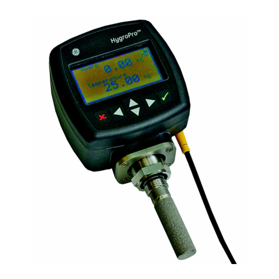
60 seconds to initialize and begin normal operation. The unit will meet its specified accuracy within 3 minutes. Figure 7 below shows a close-up view of the HygroPro display and keypad, and Figure 8 on the next page shows a complete menu map of the HygroPro setup program. -
Page 26: Menu Map
Chapter 2: Operation 2.1.1 Menu Map Figure 8: Programming Menu Map Page 20 HygroPro User’s Manual... -
Page 27: Keypad
Chapter 2: Operation 2.1.2 Keypad After entering the setup program, the keys on the HygroPro keypad (see Figure 7 on page 23) perform the following functions: enter - confirm a selection or move to the next screen • escape - cancel a selection or move to the previous screen •... -
Page 28: Entering The Setup Program
When the passcode is correct, press enter. To enter the Service menu, the factory-level passcode must be Note: entered. Page 22 HygroPro User’s Manual... -
Page 29: Selecting Measurement Parameters
Use the up and down arrow keys to select a measurement parameter and then press enter twice. Note: As an example, has been selected as the Dew Point measurement parameter to be changed. HygroPro User’s Manual Page 23... - Page 30 Use the up and down keys to change the number of decimal places and press enter. The programming sequence is now complete and you are returned to menu. View Page 24 HygroPro User’s Manual...
-
Page 31: Setting Up The Display
If you wish to change the display Contrast, at the above screen, highlight that choice and press enter. Use the arrow keys to change the Contrast value and press enter. Then press escape twice to return to the main menu. HygroPro User’s Manual Page 25... -
Page 32: Setting Up The Analog Output
Use the arrow keys to scroll to the desired output parameter and press enter. In the Output menu, select Type and press enter. The following screen appears: Select the desired output Type and press enter. Page 26 HygroPro User’s Manual... - Page 33 Repeat the above two steps to enter the value for the special Span output. In the Output menu, select Range and press enter. The following screen appears: Enter the Zero and Span values for the range, using the same procedure as above. HygroPro User’s Manual Page 27...
-
Page 34: Entering The Node Id
Test to verify the output or Normal for normal operation. 2.2.6 Entering the Node ID The Node ID is a unique network identifier that enables the HygroPro to be connected to a multi-drop network when used with PanaView™ interface software. To enter your Node ID, proceed as follows: Enter your passcode to access the setup program. -
Page 35: Setting Up The Rs485 Output
Use the up and down keys to select the desired value and press enter. Repeat the above procedure to enter the following RS485 parameters: • Parity • Stop Bits • Data Bits You have now completed the initial setup process. HygroPro User’s Manual Page 29... -
Page 36: Advanced Setup
Chapter 2: Operation 2.3 Advanced Setup The following sections describe the procedures for completing the configuration of your HygroPro transmitter. 2.3.1 Setting Up the Pressure/Temperature Displays The following steps set the displayed pressure and temperature values to Live (changing with the current measurements) or Constant (remaining the same, regardless of the current measurements). -
Page 37: Entering Sensor Calibration Data
Temperature is selected, to enter the constant temperature value. 2.3.2 Entering Sensor Calibration Data Enter your password and use the arrow keys to scroll to Calibrate. Press enter. Select Hygro Curve and press enter. and press enter. Select Row1 HygroPro User’s Manual Page 31... - Page 38 Repeat the above process to enter any available Press Curve and CS Table data points. The CS Table is required only if ppm Note: measurements will be made. Consult GE for the table values to use for your application. Page 32 HygroPro User’s Manual...
-
Page 39: Locking And Unlocking The Keypad
Use the down arrow key to select Lock Menus on the initial screen and press enter twice. The menus are now locked. To unlock the menus, just re-enter the user program as described on page 26. No further programming steps are required. HygroPro User’s Manual Page 33... - Page 40 Chapter 2: Operation Page 34 HygroPro User’s Manual...
-
Page 41: Chapter 3: Service & Maintenance
To check the version levels of your HygroPro firmware, select Versions and press enter. The information for your unit is displayed. The following HygroPro service menu options are also available: • - used to install an updated firmware version Upgrade •... -
Page 42: Moisture Probe Error Conditions
If there is a problem with the moisture probe during operation, the HygroPro is programmed to indicate the error condition via its analog output signal. To indicate a probe error condition, the analog output signal is forced to the following values: 22 mA to indicate a short circuit in the probe... -
Page 43: Replacing The Rte
) every 6 to 12 months. The optimum interval depends on the specific application. To accomplish this, either return the RTE to GE for recalibration or install a new RTE. The HygroPro electronics will automatically read and store the calibration data whenever a new or recalibrated RTE is installed. -
Page 44: Removing The Transmitter From The System
2. Carefully remove the metal plate without touching the sensor. 3. Carefully pull the probe out of the transmitter. 4. Disconnect the probe cable by turning the locknut at the top of the probe. Then, detach the sensor. Page 38 HygroPro User’s Manual... - Page 45 Chapter 3: Service & Maintenance 3.3.4 Removing the Probe from the Transmitter (cont.) Cable Locknut Probe Metal Plate Captive Screws Figure 9: Removing the Probe from the Transmitter HygroPro User’s Manual Page 39...
-
Page 46: Cleaning The Sensor And The Shield
7. Carefully replace the shield over the exposed sensor without touching the sensor. 8. Place the sensor with the installed shield in an oven set at 50°C ± 2°C (122°F ± 3.6°F) for 24 hours. Page 40 HygroPro User’s Manual... -
Page 47: Installing The Probe In The Transmitter
Repeat the cleaning cycles until two consecutive ambient air readings are identical. If the above cleaning procedure does not result in accurate readings, contact GE for assistance. HygroPro User’s Manual Page 41... - Page 48 Chapter 3: Service & Maintenance Page 42 HygroPro User’s Manual...
-
Page 49: Chapter 4: Specifications
±0.9°F (±0.5°C) from –85° to 104°F (–65° to 40°C) • ±1.8°F (±1.0°C) from –112° to –86°F (–80° to –66°C) Response Time • Less than five seconds for 63% of a step change in moisture content in either a wet-up or dry-down cycle HygroPro User’s Manual Page 43... -
Page 50: Electrical
Example: Given a 24 VDC Power Supply, Max. Load Resistance 33.33) – 300 = 500 • Cable: 6 ft (2 m), standard (consult GE for custom lengths) Input Parameters for Loop-Powered Intrinsic Safety = 28V = 0.653W = 62µH... -
Page 51: Mechanical
5 m Hg to 5,000 psig (345 bar) • Enclosure • Type 4x / IP67 Dimensions • Overall (H x W x D): 7.88 x 3.99 x 2.56 in. (200 x 101 x 65 mm) • Weight: 1.2 lb (550 g) HygroPro User’s Manual Page 45... -
Page 52: Moisture Sensor
Each sensor is individually computer-calibrated against known NIST moisture concentrations, traceable to Calibration Interval • Sensor recalibration at GE is recommended every six to twelve months, depending on the application Flow Rate • Gases: Static to 100 m/s linear velocity at a pressure of 1 atm. -
Page 53: Built-In Pressure Sensor
Accuracy • ±1% of full scale (FS) Warm-up Time • Meets specified accuracy within 3 minutes Pressure Rating • Three times the span of the available range, to a maximum of 7500 psig (518 bar) HygroPro User’s Manual Page 47... -
Page 54: Certifications
Chapter 4: Specifications 4.7 Certifications European Compliance • Complies with EMC Directive 2004/108/EC and PED 2006/95/EC for DN<25 Figure 10: HygroPro Certification Label Page 48 HygroPro User’s Manual... - Page 55 Warranty Warranty Each instrument manufactured by GE Sensing is warranted to be free from defects in material and workmanship. Liability under this warranty is limited to restoring the instrument to normal operation or replacing the instrument, at the sole discretion of GE Sensing. Fuses and batteries are specifically excluded from any liability.
- Page 56 AUTHORIZATION NUMBER (RAN), and shipping instructions for the return of the instrument to a service center will be provided. If GE Sensing instructs you to send your instrument to a service center, it must be shipped prepaid to the authorized repair station indicated in the shipping instructions.
- Page 57 GE Sensing 1100 Technology Park Drive Billerica, MA 01821 declare under our sole responsibility that the HygroPro Moisture Transmitter to which this declaration relates, is in conformity with the following standards: • EN 60079-0: 2000 • EN 60079-26: 2004 • II 1 G EEx ia IIC T4; Baseefa06ATEX0019X (Baseefa, Buxton, Derbyshire, UK - NoBo 1180) •...
- Page 60 Customer Support Centers U.S.A. The Boston Center 1100 Technology Park Drive Billerica, MA 01821 U.S.A. Tel: 800 833 9438 (toll-free) 978 437 1000 E-mail: sensing@ge.com Ireland Sensing House Shannon Free Zone East Shannon, County Clare Ireland Tel: +35 361 470291 E-mail: gesensingsnnservices@ge.com www.ge-mcs.com...
Need help?
Do you have a question about the HygroPro and is the answer not in the manual?
Questions and answers