Table of Contents
Advertisement
Advertisement
Table of Contents
Troubleshooting

Related Manuals for GE PanaFlow XMT1000


Summary of Contents for GE PanaFlow XMT1000
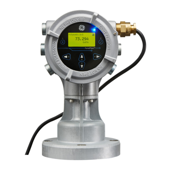
- Page 1 Oil & Gas Flow PanaFlow™ XMT1000 User’s Manual 910-313 Rev. A June 2017...
- Page 3 Oil & Gas PanaFlow™ XMT1000 Panametrics Liquid Flow Ultrasonic Transmitter User’s Manual 910-313 Rev. A June 2017 www.gemeasurement.com ©2017 General Electric Company. All rights reserved. Technical content subject to change without notice.
- Page 4 [no content intended for this page]...
-
Page 5: Table Of Contents
Contents Product Registration ..................vii Services . - Page 6 Contents Appendix A. Specifications A.1 Operation and Performance ................31 A.2 Electronics .
- Page 7 Contents D.10 Error Handling..................76 D.11 Simulation Mode .
- Page 8 Contents [no content intended for this page] PanaFlow™ XMT1000 User’s Manual...
-
Page 9: Product Registration
Please visit for more details. Terms and Conditions GE’s sales Terms and Conditions for your recent purchase of a GE product, including the applicable product Warranty, can be found on our website at the following link: www.gemeasurement.com/sales-terms-and-conditions Typographical Conventions Note: These paragraphs provide information that provides a deeper understanding of the situation, but is not essential to the proper completion of the instructions. -
Page 10: Auxiliary Equipment
Preface Auxiliary Equipment Local Safety Standards The user must make sure that he operates all auxiliary equipment in accordance with local codes, standards, regulations, or laws applicable to safety. Working Area WARNING! Auxiliary equipment may have both manual and automatic modes of operation. As equipment can move suddenly and without warning, do not enter the work cell of this equipment during automatic operation, and do not enter the work envelope of this equipment during manual operation. -
Page 11: Environmental Compliance
The PanaFlow™ XMT1000 fully complies with RoHS regulations (Directive 2011/65/EU). Waste Electrical and Electronic Equipment (WEEE) Directive GE is an active participant in Europe’s Waste Electrical and Electronic Equipment (WEEE) take-back initiative (Directive 2012/19/EU). The equipment that you bought has required the extraction and use of natural resources for its production. It may contain hazardous substances that could impact health and the environment. - Page 12 Preface [no content intended for this page] PanaFlow™ XMT1000 User’s Manual...
-
Page 13: Chapter 1. Installation
Chapter 1. Installation Chapter 1. Installation 1.1 Introduction To ensure safe and reliable operation of the XMT1000, it must be installed in accordance with the established guidelines. Those guidelines, explained in detail in this chapter, include the following topics: • Unpacking the XMT1000 •... -
Page 14: Unpacking The Xmt1000
Before removing the XMT1000 from its box, please inspect both the box and the instrument carefully. Each instrument manufactured by GE is warranted to be free from defects in material and workmanship. Before discarding any of the packing materials, account for all components and documentation listed on the packing slip. The discarding of an important item along with the packing materials is all too common. -
Page 15: Site And Clearance Considerations
Because the relative location of the flowcell and the XMT1000 transmitter is important, use the guidelines in this section to plan the XMT1000 installation. For flowcell clearance recommendations, consult the manual for your specific flow meter system or contact GE for assistance. Access to the XMT1000 flow transmitter should be uninhibited, as defined by the minimum clearance distances around the enclosure specified in Figure 3 on page 4. -
Page 16: Vibration Exposure Considerations
Chapter 1. Installation 1.4.1 Access to the Meter (cont.) 12 in. (300 mm) CLEARANCE MINIMUM RECOMMENDED FOR SERVICE ACCESS 12 in. (300 mm) CLEARANCE 12 in. (300 mm) CLEARANCE MINIMUM RECOMMENDED MINIMUM RECOMMENDED FOR CABLE ENTRY FOR CABLE ENTRY 1000 SERIES ELECTRONICS 12 in. -
Page 17: Local Mounting
Chapter 1. Installation 1.4.4 Local Mounting The XMT1000 accuracy is affected by the flowcell location in the process piping and on the orientation of the transducers. Thus, in addition to accessibility for maintenance, adhere to the following installation guidelines: • Locate the flowcell so that there are at least 10 pipe diameters of straight, undisturbed flow upstream and 5 pipe diameters of straight, undisturbed flow downstream from the measurement point (see Figure 4 below). -
Page 18: Remote Mounting
Chapter 1. Installation 1.4.5 Remote Mounting The standard XMT1000 enclosure is a powder-coated, aluminum, IP67 explosion-proof enclosure. Typically, the enclosure is mounted as close as possible to the transducers. When choosing a site for a remote-mount installation, which is recommended for process temperatures exceeding 150°C, make sure the location permits easy access to the enclosure for programming, maintenance and service. -
Page 19: Making The Electrical Connections
Chapter 1. Installation 1.5 Making the Electrical Connections This section contains instructions for making all the necessary electrical connections for the XMT1000 flow transmitter. Refer to Figure 6 on page 8 for a complete wiring diagram. Note: Both flying lead and MCX transducer connectors are shown in the figure for completeness. Only the type of connector appropriate for each meter ordered will be installed on the PCB. - Page 20 Chapter 1. Installation Making the Electrical Connections (cont.) Figure 6: XMT1000 Terminal Board Wiring Diagram (ref. dwg. 702-2040) PanaFlow™ XMT1000 User’s Manual...
-
Page 21: Wiring The Analog Outputs
Chapter 1. Installation 1.5.1 Wiring the Analog Outputs The standard configuration of the XMT1000 flow transmitter includes one isolated 4-20 mA analog output. Connections to this output may be made with standard twisted-pair wiring, but the current loop impedance for this circuit must not exceed 600 ohms. -
Page 22: Wiring The Digital Output
Chapter 1. Installation 1.5.2 Wiring the Digital Output The standard XMT1000 flow transmitter configuration includes one isolated digital output, which can be used as a totalizer (pulse) output, a frequency output, or a calibration port. Wiring this output requires completion of the following general steps: 1. -
Page 23: Wiring The Modbus/Service Port
Chapter 1. Installation 1.5.3 Wiring the Modbus/Service Port The XMT1000 flow transmitter is equipped with a Modbus communication port for either a connection to Vitality (PC software) or to a separate control system. The port is an RS485 interface. IMPORTANT: The maximum cable length for an RS485 connection is 4000 ft (1200 m). To wire to this RS485 serial port, refer to Figure 6 on page 8 and complete the following steps: 1. -
Page 24: Wiring The Line Power
Chapter 1. Installation 1.5.4 Wiring the Line Power The XMT1000 may be ordered for operation with power inputs of either 100-240 VAC or 12-28 VDC. The label on the side of the enclosure lists the meter’s required line voltage and power rating. Be sure to connect the meter to the specified line voltage only. -
Page 25: Chapter 2. Programming
Chapter 2. Programming Chapter 2. Programming 2.1 Introduction This chapter provides instructions for programming the various features of the XMT1000 flow transmitter. Before the XMT1000 can begin taking measurements, settings for the User Preferences and Inputs/Outputs must be entered and tested. -
Page 26: Passcodes
Chapter 2. Programming Using the Magnetic Keypad (cont.) Above the display, the blue light is for power indication and the red light is for system health indication. Once system power is applied, the blue light stays on until power is lost. The red light blinks when the system is in error. When the red light is off - the system is operating without error. -
Page 27: Glossary Of Terms
Chapter 2. Programming 2.4 Glossary of Terms • Backlight: The LCD display backlight has three user-adjustable parameters. The brightness, the contrast, and the length of inactivity which triggers automatic shutdown can be individually set within available limits. • Error Handling: The manner in which various XMT1000 outputs respond to automatically generated system errors can be set by the user by selecting the options from a drop-down list. -
Page 28: Menu Maps
Chapter 2. Programming 2.5 Menu Maps Use the menu maps in this section to program the desired XMT1000 features. • "Measurement Display Menu Map (Rev. 10)" on page 17 • "Main Menu Map (Rev. 10)" on page 18 • "SYSTEM Menu Map (Rev. 10)" on page 19 •... -
Page 29: Measurement Display Menu Map (Rev. 10)
Chapter 2. Programming Menu Maps (cont.) Press to Enter the Display Measurement Menu Inventory Reynolds Standard Batch Velocity Soundspeed Diagnostics Volumetric Total Total K-Factor Reylnolds Actual On Board Mass K-Factor Temperature Volumetric Number Reverse Forward Ch 1 Ch 2 Ch 3 Time Flow Values... -
Page 30: Main Menu Map (Rev. 10)
Chapter 2. Programming Menu Maps (cont.) Main Menu Keypad Program Display Format Diagnostics Lockout When the keypad is locked, press [ ], [ ], [ ] to open the password 1 Variable 2 Variables Totalizer screen. Enter an Admin password to unlock the keypad. -
Page 31: System Menu Map (Rev. 10)
Chapter 2. Programming Menu Maps (cont.) Operator/Admin Password SYSTEM MAIN Board I/O OPTION Boards HART SENSOR SETUP CALIBRATION ADVANCED Change Measure Meter Setup Display Flow Units Settings Password Velocity Backlight Language Operator Flow Limits System Date Always On Zero Cutoff Admin Not visible in Operator menu. -
Page 32: Main Board I/O Menu Map (Rev. 10)
Chapter 2. Programming Menu Maps (cont.) Operator/Admin Password SYSTEM MAIN Board I/O OPTION Boards HART SENSOR SETUP CALIBRATION ADVANCED Modbus/Service Analog Output Digital Output Port Bit/Parity Base Value Measurement Baud Rate Actual Velocity 2400 4800 8 no Full Value Pulse 8 odd Volumetric Standard... -
Page 33: Option Boards Menu Map (Rev. 10)
Chapter 2. Programming Menu Maps (cont.) Operator/Admin Password SYSTEM MAIN Board I/O OPTION Boards HART SENSOR SETUP CALIBRATION ADVANCED HART Hardware Revision Analog Software HART Info Output Revision (Admin access only) Hardware Analog Revision Base Value Measurement Software Actual Revision Velocity Full Value Volumetric... -
Page 34: Sensor Setup Menu Map (Rev. 10)
Chapter 2. Programming Menu Maps (cont.) Operator/Admin Password SYSTEM OPTION Boards HART SENSOR SETUP CALIBRATION ADVANCED MAIN Board I/O Channel Pipe OD Pipe ID/WT Configure Ch 1 Ch 2 Ch 3 ID-In ID-mm WT-In WT-mm Wall Pipe OD Pipe ID Thickness Configure Transducer... -
Page 35: Calibration Menu Map (Rev. 10)
Chapter 2. Programming Menu Maps (cont.) Operator/Admin Password SYSTEM MAIN Board I/O OPTION Boards HART SENSOR SETUP CALIBRATION ADVANCED Calibration Calibration Calibration Calibration Calibration Calibration Type Config Points Table Factor Velocity Composite Reynolds Gate Number Frequency Figure 14: CALIBRATION Menu Map (Rev. 10) PanaFlow™... -
Page 36: Advanced Menu Map (Rev. 10)
Chapter 2. Programming Menu Maps (cont.) Operator/Admin Password SYSTEM MAIN Board I/O OPTION Boards HART SENSOR SETUP CALIBRATION ADVANCED Error Log Signal Setup Reset Settings Flash Update Limits Active Tw Transmit Volt Corr Peak % Main Board Update Limit Velocity Low Limit Reset to Ch 1... -
Page 37: Chapter 3. Error Codes And Troubleshooting
Chapter 3. Error Codes and Troubleshooting Chapter 3. Error Codes and Troubleshooting 3.1 Error Display in the User Interface The bottom line of the LCD displays a single, top priority error message during Measurement Mode. This line, called the Error Line, includes two parts: Error header and Error String. The Error header indicates the error pattern and error number, while the Error string gives a detailed description of the error information 3.1.1 Error Header Table 2: Error Header... -
Page 38: Flow Error String
E28: Software Fault There is a software malfunction This is a software malfunction. Try power cycling the meter. If the error persists after power cycle, contact GE factory. E29: Velocity Warning The measured velocity exceeds This error may be caused by incorrect programming, poor programmed warning limits. -
Page 39: Diagnostics
Usually, flowcell problems are either fluid problems or pipe problems. Read the following sections carefully to determine if the problem is indeed related to the flowcell. If the instructions in this section fail to resolve the problem, contact GE for assistance. 3.2.2a Fluid Problems Most fluid-related problems result from a failure to observe the flow meter system installation instructions. - Page 40 Inaccurate pipe measurements. The accuracy of the flow rate measurements is no better than the accuracy of the programmed pipe dimensions. For a flowcell supplied by GE, the correct data will be included in the documentation. For other flowcells, measure the pipe wall thickness and diameter with the same accuracy desired in the flow rate readings.
-
Page 41: Transducer/Buffer Problems
3.2.3 Transducer/Buffer Problems Ultrasonic transducers are rugged, reliable devices. However, they are subject to physical damage from mishandling and chemical attack. The following list of potential problems is grouped according to transducer type. Contact GE if you cannot solve a transducer-related problem. - Page 42 Chapter 3. Error Codes and Troubleshooting [no content intended for this page] PanaFlow™ XMT1000 User’s Manual...
-
Page 43: Appendix A. Specifications
Appendix A. Specifications Appendix A. Specifications A.1 Operation and Performance Fluid Types Acoustically conductive fluids, including most clean liquids, and many liquids with entrained solids or gas bubbles. Maximum void fraction depends on transducer, interrogation carrier frequency, path length and pipe configuration. Transducer Types All liquid wetted transducers Pipe Sizes... -
Page 44: Electronics
Standard: 100-240 VAC (50/60 Hz) Optional: 12 to 28 VDC Power Consumption 15 Watts maximum Wiring Connection Conduit entries include 6 x 3/4” NPT and 1 x 1/2” NPT on bottom, consult GE for available adapters PanaFlow™ XMT1000 User’s Manual... - Page 45 Appendix A. Specifications Electronics (cont.) Electronics Classifications (Pending) USA/Canada- Explosion-proof Class I, Division 1, Groups B, C, & D ATEX - Flameproof II 2 G Ex d IIC T6 Gb IECEx - Flameproof Ex d IIC T6 Gb RoHS compliance (Directive 2011/65/EU) CE Marking (EMC directive 2014/30/EU, LVD 2014/35/EU) WEEE compliance (Directive 2012/19/EU) Electronics Mounting...
- Page 46 [no content intended for this page] PanaFlow™ XMT1000 User’s Manual...
-
Page 47: Appendix B. Modbus Communication
Appendix B. Modbus Communication B.1 Modbus Protocol In general, the PanaFlow XMT1000 flow meter follows the standard Modbus communications protocol defined by the reference MODBUS APPLICATION PROTOCOL SPECIFICATION V1.1b. This specification is available at www.modbus.org on the Internet. With this reference as a guide, an operator could use any Modbus master to communicate with the flow meter. - Page 48 Appendix B. Modbus Communication Table 6: XMT1000 Modbus Register Map - Revision 4.19 (cont.) Reg # Access Size in in Hex Level Register ID Description Units RO/RW Bytes Format Operator eUnit_NS Global Unit group 11 for unitless INT32 Nano Second Operator eUnit_Percent Global Unit group 12 for unitless INT32...
- Page 49 Appendix B. Modbus Communication Table 6: XMT1000 Modbus Register Map - Revision 4.19 (cont.) Reg # Access Size in in Hex Level Register ID Description Units RO/RW Bytes Format Operator eSystem_ Meter Tag unitless CHAR * 16 TagShort Operator eSystem_ Long Tag unitless CHAR * 32...
- Page 50 Appendix B. Modbus Communication Table 6: XMT1000 Modbus Register Map - Revision 4.19 (cont.) Reg # Access Size in in Hex Level Register ID Description Units RO/RW Bytes Format eSystem_ Admin user password unitless INT32 Admin Password eSystem_MCU MCU bootloader version unitless INT32 _Bootloader_...
- Page 51 Appendix B. Modbus Communication Table 6: XMT1000 Modbus Register Map - Revision 4.19 (cont.) Reg # Access Size in in Hex Level Register ID Description Units RO/RW Bytes Format Display Int RW Operator eDisplay_ Display Language unitless INT32 Language Viewer eDisplay_Var1_ Display Variable_1 unitless INT32...
- Page 52 Appendix B. Modbus Communication Table 6: XMT1000 Modbus Register Map - Revision 4.19 (cont.) Reg # Access Size in in Hex Level Register ID Description Units RO/RW Bytes Format Operator eDisplay_Unit Unit type for actural unitless INT32 Type_ActVol volumetric Operator eDisplay_Unit Unit type for standard unitless INT32...
- Page 53 Appendix B. Modbus Communication Table 6: XMT1000 Modbus Register Map - Revision 4.19 (cont.) Reg # Access Size in in Hex Level Register ID Description Units RO/RW Bytes Format Log Int RO eLog_ Number of records unitless INT32 NumRecord MAIN Aout Real RW 1000 1000 Operator...
- Page 54 Appendix B. Modbus Communication Table 6: XMT1000 Modbus Register Map - Revision 4.19 (cont.) Reg # Access Size in in Hex Level Register ID Description Units RO/RW Bytes Format 1034 Operator eAout4_ Analog Out 4 Span (IEEE 32 bit) SpanValue 1036 Operator eAout4_...
- Page 55 Appendix B. Modbus Communication Table 6: XMT1000 Modbus Register Map - Revision 4.19 (cont.) Reg # Access Size in in Hex Level Register ID Description Units RO/RW Bytes Format 11B8 Operator eAout4_Unit Analog Out 4 Unit code unitless INT32 MAIN Aout Real RO 1200 MAIN Aout Int RO 1300...
- Page 56 Appendix B. Modbus Communication Table 6: XMT1000 Modbus Register Map - Revision 4.19 (cont.) Reg # Access Size in in Hex Level Register ID Description Units RO/RW Bytes Format IO Aout1 Max Real RO 1620 1620 eAout3_ Maximum Analog Out 3 (IEEE 32 bit) ErrValue_ Error Handling Value...
- Page 57 Appendix B. Modbus Communication Table 6: XMT1000 Modbus Register Map - Revision 4.19 (cont.) Reg # Access Size in in Hex Level Register ID Description Units RO/RW Bytes Format 1A02 eAout1_ Minumum Analog Out 1 (IEEE 32 bit) ZeroValue_Min Zero 1A04 eAout1_ Minumum Analog Out 1...
- Page 58 Appendix B. Modbus Communication Table 6: XMT1000 Modbus Register Map - Revision 4.19 (cont.) Reg # Access Size in in Hex Level Register ID Description Units RO/RW Bytes Format 1A36 eAout4_ Minumum Analog Out 4 (IEEE 32 bit) TestValue_Min Test Value (Percent of Span) 1A38 eAout4_...
- Page 59 Appendix B. Modbus Communication Table 6: XMT1000 Modbus Register Map - Revision 4.19 (cont.) Reg # Access Size in in Hex Level Register ID Description Units RO/RW Bytes Format 2190 Operator eDout1_ Output_1 Alarm unitless INT32 AlarmAddress Measument Register Address 2192 Operator eDout1_...
- Page 60 Appendix B. Modbus Communication Table 6: XMT1000 Modbus Register Map - Revision 4.19 (cont.) Reg # Access Size in in Hex Level Register ID Description Units RO/RW Bytes Format TBD Dout2 Int RW 2500 2500 Operator eDout2_ Output_2 Test Pulse Value unitless INT32 PulseTestValue...
- Page 61 Appendix B. Modbus Communication Table 6: XMT1000 Modbus Register Map - Revision 4.19 (cont.) Reg # Access Size in in Hex Level Register ID Description Units RO/RW Bytes Format 25A4 Operator eDout2_ Output_2 Pulse unitless INT32 PulseAddress Measument Register Address 25A6 Operator eDout2_ Output_2 Pulse output...
- Page 62 Appendix B. Modbus Communication Table 6: XMT1000 Modbus Register Map - Revision 4.19 (cont.) Reg # Access Size in in Hex Level Register ID Description Units RO/RW Bytes Format 2A8A eDout2_ Maximum Output_2 (IEEE 32 bit) ControlValue Control Ouput Value _Max MAIN Dout Max Int RO 2B00...
- Page 63 Appendix B. Modbus Communication Table 6: XMT1000 Modbus Register Map - Revision 4.19 (cont.) Reg # Access Size in in Hex Level Register ID Description Units RO/RW Bytes Format 2E84 eDout2_Freq Minumum Output_2 1, 9, 14, 17, (IEEE 32 bit) BaseValue_Min Frequency Base Value 2E86...
- Page 64 Appendix B. Modbus Communication Table 6: XMT1000 Modbus Register Map - Revision 4.19 (cont.) Reg # Access Size in in Hex Level Register ID Description Units RO/RW Bytes Format 3506 Viewer eFFUnitType_ Fieldbus unit type register unitless INT32 Velocity_E for velocity 3508 Viewer eFFUnitType_...
-
Page 65: Appendix C. Hart Communication
C.1 Wiring the XMT1000 to the HART Communicator When connecting a HART communicator to the wiring terminals on the PanaFlow XMT1000 electronics terminal board, the circuit must be terminated in an appropriate resistive load, as shown in Figure 16 below. The HART communicator is connected in parallel with that load. -
Page 66: Hart Menu Maps
Appendix C. HART Communication C.3 HART Menu Maps For reference while programming the XMT1000, see the following HART menu maps: • “HART Output Menu Map” on page 54 • “HART Review Menu Map” on page 55 C.3.1 HART Output Menu Map Root Menu PV Loop Setup Menu... -
Page 67: Hart Review Menu Map
Appendix C. HART Communication C.3.2 HART Review Menu Map Root Menu PV Loop Setup Menu QV Value Product Type TV Value SV Value PV Value Current Login Logout Squawk Service Menu* Review Menu Clear Totals *Editable only by Admin/Operator users Sensor Setup I/O Options Use Preference... - Page 68 Appendix C. HART Communication [no content intended for this page] PanaFlow™ XMT1000 User’s Manual...
-
Page 69: Appendix D. Foundation Fieldbus Communication
Appendix D. Foundation Fieldbus Communication Appendix D. Foundation Fieldbus Communication D.1 Introduction Fieldbus is a bi-directional digital communication protocol for field devices, which offers an advancement in technologies for process control systems and is widely employed by numerous field devices. The XMT1000 FF option is designed to the specification standardized by the Fieldbus Foundation, and provides interoperability with devices produced by other manufacturers. -
Page 70: Connection
Appendix D. Foundation Fieldbus Communication D.2.3 Connection Connect the Fieldbus wires to P1 on the terminal PCB (see Figure 20 below). GE recommends using the top right rear port on the enclosure. IMPORTANT: Please make sure to follow all local installation guidelines. - Page 71 Appendix D. Foundation Fieldbus Communication D.2.4 FISCO [Fieldbus Intrinsically Safe Concept] (cont.) Note: The XMT1000 FISCO control drawing is GE drawing #752-584. Please consult the factory for a copy of the drawing. Attention! The FISCO cover must be installed to comply with FISCO guidelines.
-
Page 72: Dd File
D.2.5 DD File www.fieldbus.org The DD file can be found on the Foundation Fieldbus website under GE as manufacturer and XMT1000 as model. It may also be found on the DCS vendor website if available. D.2.6 Default Node Address The default node address for each XMT1000 flow meter from the factory is 17 (see Figure 22 below). This should be changed during commissioning. -
Page 73: Specifications
Appendix D. Foundation Fieldbus Communication D.3 Specifications D.3.1 General Manufacturer Name: GE Manufacturer ID (Hex): 004745 Model: XMT1000 Device Type: 0010 FF Device Revision: For latest, see Fieldbus Foundation website FISCO Compliant: Yes Hazardous Location Certs: See drawing 752-584 ITK Revision: 6.2 Protocol: H1 Protocol Baud (bps): 31.25k... -
Page 74: User Layer
Appendix D. Foundation Fieldbus Communication D.3.4 User Layer FB Application Manufacturer: Softing AG Function Blocks: 5-AI(e), 1-PID Supports Block Instantiation: No Firmware Upgrade over Fieldbus: No Configuration Write Protect: HW Jumper on PCB D.3.5 Function Blocks Resource Block Class Type: Enhanced (Field Diagnostics) Transducer Blocks: XMIT, COMPOSIT CH, CH 1, CH 2, CH 3 Transducer Block Class Type: Custom Function Blocks: AI (5), PID... -
Page 75: Resource Block
Appendix D. Foundation Fieldbus Communication D.4 Resource Block The Resource Block provides common information about the XMT1000 Foundation Fieldbus implementation. The user can find FF revision numbers, set passwords and configure the NAMUR NE107 bit map. D.4.1 FF Revision Figure 24 below shows the Foundation Fieldbus SW and HW versions in the XMT1000 Resource Block, and includes an FF Revision for both. -
Page 76: Password
Appendix D. Foundation Fieldbus Communication D.4.2 Password A password must be entered to change XMT1000 system parameters. This can be done using Foundation Fieldbus. There are different levels of security for different Passwords ( Admin or Operator ). Please see the standard manual for more detail on password levels. -
Page 77: Namur Ne107
The NAMUR NE107 recommendation specifies that detailed device-specific diagnostics are summarized as four simple status signals. The diagnostics are set to defaults by GE, but they can be modified to any other level by the user. The four status signals are: •... - Page 78 Appendix D. Foundation Fieldbus Communication D.4.3 NAMUR NE107 (cont.) The NAMUR NE107 Errors and their Default Categories in the XMT1000 Resource Block are listed in Table 7 below. Table 7: NAMUR NE107 Errors and XMT1000 Default Categories Error Sub-Error Description Default Category CRC Configuration Error Persistent Parameter CRC Fault...
-
Page 79: Xmit Transducer Block
Appendix D. Foundation Fieldbus Communication D.5 XMIT Transducer Block The XMIT transducer block contains parameters that can be transmitted onto the Fieldbus via the AI block. The user can view real time data and select the units for each of the parameters (see Figure 27 below). Figure 27: Measurement Parameters and Units in XMIT Transducer Block PanaFlow™... -
Page 80: Units
Appendix D. Foundation Fieldbus Communication D.5.1 Units The measurement parameters found on the XMIT Transducer Block have several selectable units. Table 8 below lists the available units for each parameter. Note: The units can only be changed using an Admin password. Make sure the selected units agree between the XMIT Transducer Block and the AI Block . -
Page 81: Composite Transducer Block
Appendix D. Foundation Fieldbus Communication D.6 Composite Transducer Block The Composite Transducer Block provides the measurement values and programmable parameters that are common to all three paths. Figure 28 below shows the Composite Transducer Block and Table 9 on page 70 lists the Measurements and Parameters that are available. - Page 82 Appendix D. Foundation Fieldbus Communication Composite Transducer Block (cont.) Table 9: Available Measurement Values and Parameters in the Composite TB Composite TB Measurements and Parameters Measurement Parameter BATCH_FWD_TOTALS BATCH_REV_TOTALS BATCH_TOTAL_TIME SOUND_SPEED INVENTORY_FWD_TOTALS INVENTORY_REV_TOTALS INVENTORY_TOTAL_TIME MULTI_KFACTOR REYNOLDS_KFACTOR CURRENT_OPERATING_TEMP STANDARD_VOLUMETRIC BATCH_NET_TOTALS ERROR_STATUS HEALTH_CODE REPORTED_ERROR GATE_INPUT_STATE...
- Page 83 Appendix D. Foundation Fieldbus Communication Table 9: Available Measurement Values and Parameters in the Composite TB (cont.) Composite TB Measurements and Parameters Measurement Parameter VELOCITY_WARN_HIGH_LIMIT REFERENCE_DENSITY SOS_LOW_LIMIT, SOS_HIGH_LIMIT MULTIK_VELREY_1-12, MULTIK_KFACTOR_1-12 REYNOLDS_CORRECTION FLUID_SUPPLY_TEMPERATURE FLUID_RETURN_TEMPERATURE SOS_LOW_LIMIT SOS_HIGH_LIMIT MULTIK_VELREY MULTIK_KFACTOR PATHCONFIGURRATION HARDWARE_REVISION SOFTWARE_REVISION UMPU_SERIAL_NUMBER TOTALIZER_CMD SENSOR_SERIAL_NUMBER...
-
Page 84: Clearing The Totalizer
Appendix D. Foundation Fieldbus Communication D.6.1 Clearing the Totalizer Batch totals can be controlled through Foundation Fieldbus (see Figure 29 below). The user can start, stop, or reset batch totalizers by setting the option on the TOTALIZER_CMD function of the Composite Transducer Block . To set the totalizers from the Foundation Fieldbus: 1. -
Page 85: Channel Transducer Block
Appendix D. Foundation Fieldbus Communication D.7 Channel Transducer Block The CH1 , CH2 and CH3 transducer blocks show the measurement values and programmable parameters for each of the three paths. Figure 30 below shows the Channel Transducer Block , and Table 10 on page 74 lists the measurements and parameters that are available. - Page 86 Appendix D. Foundation Fieldbus Communication Channel Transducer Block (cont.) Table 10: Available Measurement Values and Parameters in the Channel TB Channel TB Measurements and Parameters Measurement Parameter CH_SOUND_SPEED CH_TRANSIT_TIME_UP CH_TRANSIT_TIME_DN CH_DELTA_T CH_UP_SIGNAL_QUALITY CH_DN_SIGNAL_QUALITY CH_UP_AMP_DISC CH_DN_AMP_DISC CH_GAIN_UP CH_GAIN_DN CH_SNR_UP CH_SNR_DN CH_UP_PEAK CH_DN_PEAK CH_PEAK_PCT_UP CH_PEAK_PCT_DN...
-
Page 87: Analog Input Block
Appendix D. Foundation Fieldbus Communication D.8 Analog Input Block The Analog Input ( AI ) Block (see Figure 31 below) is designed as a generalized signal conditioning function. The output from an AI block can be connected to the Fieldbus. The AI block receives and processes data measured by the Transducer Block and provides additional functions such as scaling, filtering, alarm generation, and trending. -
Page 88: Error Handling
Appendix D. Foundation Fieldbus Communication D.10 Error Handling The flow meter publishes the error status on the Fieldbus along with the real data. The error status can be seen in the CH_x_Reported Error parameter on the Channel Transducer Block . In addition, the Quality parameter shown with each of the process variables reports the error. - Page 89 Appendix D. Foundation Fieldbus Communication D.10 Error Handling (cont.) Whenever the meter is in measurement error, the quality bit for the published parameter shows bad quality (see Figure 33 below). To change the quality bit to good, the measurement error at the meter must be removed. Notice the QUALITY.STATUS field shows as Bad and the SUBSTATUS field shows as Sensor Failure .
-
Page 90: Simulation Mode
Appendix D. Foundation Fieldbus Communication D.11 Simulation Mode Simulation mode allows the user to test the FF implementation without the instrument providing real data. The meter PCB is shipped with simulation mode disabled. To enable simulation mode, complete the following steps: CAUTION! To prevent damage to the electronic components, always use ESD protection whenever handling printed circuit boards. -
Page 91: Fieldbus Troubleshooting Guide
Appendix D. Foundation Fieldbus Communication D.12 Fieldbus Troubleshooting Guide See Table 11 below for suggested solution to possible Fieldbus problems. Table 11: XMT1000 FF Troubleshooting Guide Problem Presumed Cause Remedy Communication between DCS and Wiring unconnected, broken or Correct wiring between XMT1000 XMT1000 FF cannot be established shorted and spur device coupler. -
Page 92: Dpi620 Ff Modular Communicator
Appendix D. Foundation Fieldbus Communication D.13 DPI620 FF Modular Communicator For local diagnostic capability with the XMT1000 FF option, GE Measurement and Control recommends the DPI620G-FF Genii advanced modular calibrator and HART/Fieldbus communicator. The calibrator is available in an IS version as well ( DPI620G-IS-FF ). -
Page 93: Index
Index Index Fluid ..... 27 Physical Requirements Analog Outputs ....... 27 Problems . - Page 94 Index Pipe Transducers ......28 ........6 Measurements Cables .
- Page 96 Customer Support Centers U.S.A. The Boston Center 1100 Technology Park Drive Billerica, MA 01821 U.S.A. Tel: 800 833 9438 (toll-free) 978 437 1000 E-mail: custcareboston@ge.com Ireland Sensing House Shannon Free Zone East Shannon, County Clare Ireland Tel: +353 61 61470200 E-mail: gesensingsnnservices@ge.com An ISO 9001-2008 Certified Company www.gemeasurement.com/quality-certifications...
Need help?
Do you have a question about the PanaFlow XMT1000 and is the answer not in the manual?
Questions and answers