
Related Manuals for GE Masoneilan 12420


Summary of Contents for GE Masoneilan 12420
- Page 1 GE Oil & Gas 12400 Masoneilan* Series Level Transmitter/Controller Instruction Manual & Safety Guide GE Data classification: Public...
- Page 3 SHOULD PARTICULAR PROBLEMS ARISE WHICH ARE NOT COVERED SUFFICIENTLY FOR THE CUSTOMER/OPERATOR'S PURPOSES THE MATTER SHOULD BE REFERRED TO GE. THE RIGHTS, OBLIGATIONS AND LIABILITIES OF GE AND THE CUSTOMER/OPERATOR ARE STRICTLY LIMITED TO THOSE EXPRESSLY PROVIDED IN THE CONTRACT RELATING TO THE SUPPLY OF THE EQUIPMENT.
-
Page 4: Table Of Contents
NSTRUMENT COUPLING TO THE TORQUE TUBE Appendix G – FAILSAFE / VIEW ERROR Menus ....76 to 77 7.2. T ............24 RANSMITTER CONFIGURATION 7.3. T .............. 25 RANSMITTER CALIBRATION 2 | GE Oil & Gas ® 2014 General Electric Company. All rights reserved. -
Page 5: General
Not intended for use in life support systems. Items sold by GE are warranted to be free from defects in material and workmanship for a period of one year from the date of first use or eighteen (18) months from the date of delivery, whichever occurs first, provided such items are used according to all relevant recommendations and instructions from GE. -
Page 6: Description - Operation
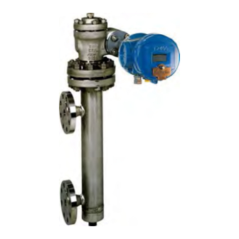
1.1. PRINCIPLE OF OPERATION The Masoneilan 12400 Series instrument from GE is a 2-wire, loop powered, digital displacement level transmitter/controller with HART communication that uses field proven buoyancy and torque tube principles. -
Page 7: Protection Standards
2. Protection standards Installation in a hazardous atmosphere must be performed in accordance with the requirements specified in the applicable standard for protection against explosion. WARNING: IMPROPER REPLACEMENT OR SUBSTITUTION OF ELECTRONIC COMPONENTS OR OF CERTAIN PARTS WHOSE CHARACTERISTICS DO NOT MEET REQUIREMENTS OF THE APPLICABLE STANDARDS FOR EXPLOSION PROTECTION MAY VOID THIS PROTECTION. -
Page 8: Fm / Fmc Certifications
2.2.3. I NTRINSICALLY AFE REQUIREMENTS Wiring must be in accordance with ES-749 (see Section 2.2.6) and must conform to national and local standards for intrinsically safe installation. 6 | GE Oil & Gas ® 2014 General Electric Company. All rights reserved. -
Page 9: Description Of Explosion Proof And Intrinsic Safety Marking
2.2.4. D ESCRIPTION OF EXPLOSION PROOF AND INTRINSIC SAFETY MARKING The label may not appear exactly as shown, but must contain the information listed below. Additional information NOT pertaining to FM approval is allowed on the label. SERIAL PERMANENTLY MARK WARNING: PROTECTION TYPE. -
Page 10: Repair
Only qualified service personnel are permitted to make repairs. Replace ONLY with genuine Masoneilan parts from GE. Only Masoneilan parts from GE are permitted. This includes not only the major assemblies but also mounting screws and “O” rings. No substitutions with non-Masoneilan parts are permitted. - Page 11 2.2.6. ES-479 I NTRINSICALLY NSTALLATION IRING EQUIREMENTS Each intrinsically safe cable must include a grounded shield or be run in a separate metal conduit. NON-HAZARDOUS LOCATION - UNSPECIFIED EXCEPT THAT BARRIERS MUST NOT BE SUPPLIED FROM NOR CONTAIN UNDER NORMAL OR ABNORMAL CONDITIONSA SOURCE OF POTENTIAL WITH RESPECT TO EARTH IN EXCESS OF 250 HAZARDOUS LOCATION VOLTS RMS OR 250 VOLTS DC.
-
Page 12: Notes For Intrinsically Safe Installation
A.C. test voltage of 500 Volts R.M.S. to earth or frame of the apparatus for one minute. Installation must be in accordance with GE’s guidelines. The installation including the barrier earthing requirements must comply with the installation requirements of the country of use. - Page 13 Note 8: Barrier type The barriers may be active or passive and from any certified manufacturer for FMRC and CSA as long as the barriers comply with the listed entity parameters. Note 9: Use in dust atmosphere Dust-tight conduit seal must be used when installed in dust hazard environments. Note 10: Multiple protection approvals A device which has previously been installed without an approved IS barrier must NEVER be used subsequently in an intrinsically safe system.
-
Page 14: Marking - Numbering System
6 – Other approvals Screwed, BW or SW (based on ATEX/IEC approvals) 7 – Other approvals (not based on ATEX/IEC approvals) Note: only the Transmitter function is SIL certified. 12 | GE Oil & Gas ® 2014 General Electric Company. All rights reserved. -
Page 15: Installation
4. Installation 4.1. STORAGE AND CONDITION AT DELIVERY Level instruments have been carefully packed in our premises to prevent them from damage during handling and transportation. Units must be stored in an area where temperatures are between -50 °C and +93 °C. Units are factory dry calibrated (simulation by weight) to the service specific gravity specified by the customer. -
Page 16: Internal Mounting
Right hand mounting is optional. To reverse instrument case mounting, refer to Section 9 - Maintenance. Right mounting Left mounting (top view) (top view) Figure 7 14 | GE Oil & Gas ® 2014 General Electric Company. All rights reserved. -
Page 17: Case Description
5. Case description The purpose of this section is to describe the various instrument sub-assemblies to facilitate their use and maintenance. See figures 8 to 13. 5.1. ELECTRONIC COMPARTMENT The electronics compartment, located at the front of the instrument, can be accessed by removing the main cover (281). This main cover is equipped with a glass (251) and three explosion proof pushbuttons (260). -
Page 18: Wiring And Connections
30 VDC across switch terminals and 1 A cannot exist simultaneously; doing so will result in failure of the digital output circuit. 16 | GE Oil & Gas ® 2014 General Electric Company. All rights reserved. - Page 19 Terminals for local HART ® communication 90 or 90A 90 or 90A Figure 11 Case External side view of case Cross-section back view Figure 12 Front view ® 2014 General Electric Company. All rights reserved. Masoneilan 12400 Series Transmitter/Controller Instruction Manual | 17...
- Page 20 Screw ■ 96 1 Clamp 124 1 Serial plate ● Recommended spare parts ■ Spare parts available 1) These 3 rings are part of a kit. 18 | GE Oil & Gas ® 2014 General Electric Company. All rights reserved.
-
Page 21: Operating The Instrument
All digital settings of the 12400 instrument are made by means of three pushbuttons and a liquid crystal display on the front of the instrument, or using HART communication handheld terminals or GE’s Masoneilan software: ValVue , ValVue AMS Snap-on and ValVue PRM . -
Page 22: Pushbuttons Menus Description
6.1.4.4. FILTERING Menu (Appendix D) This menu allows the setting of the two filterings available in the instrument: ♦ Damping adjustment (analog filtering). ♦ Smart filtering parameters tuning. 20 | GE Oil & Gas ® 2014 General Electric Company. All rights reserved. - Page 23 6.1.4.5. 4-20mA GENERATOR Menu (Appendix E) This menu enables generation of a loop current to a defined value independently of true level measurement. This function is of help to set another instrument (such a positioner) in series in the loop, by generating the required output current. 6.1.4.6.
-
Page 24: Commissioning
Curve of Half Level Simulation in a Liquid with S.G. be used for specific gravities (or the difference between 0.7 and 1.4 of SG) ranging from 0.15 to 2xd3. 22 | GE Oil & Gas ® 2014 General Electric Company. All rights reserved. - Page 25 c. Enter the BASIC SETUP menu to display [COUPLNG:%]. d. Look through the side orifice and verify that the screw (62) coupling end of the beam (54) is loose and that the spring arm (242) is disengaged from the pin (243). Through the 3/4 ” NPT hole at the bottom of the case, push the flexure (59) from left to right with your finger to verify it is possible to move the beam (54).
-
Page 26: Transmitter Configuration
In case of failsafe signal use ([FAIL LOW] or [FAIL HIGH]), check that loop current variations are in line with process and safety rules implemented into the Distributed Control System. ♦ See Appendixes A to G which describe operating and setting menus. 24 | GE Oil & Gas ® 2014 General Electric Company. All rights reserved. -
Page 27: Transmitter Calibration
7.3. TRANSMITTER CALIBRATION 7.3.1. O PERATING RULES AND CALIBRATION PRINCIPLE The purpose of this chapter is to detail internal device operating rules to understand names of functions and describe actions generated by the embedded firmware during calibration. Advanced settings are also described to answer user constraints. In some cases, the user can avoid doing a new calibration following a process change or can enable a level measurement on a specific range different than the standard one. - Page 28 The level indication corresponding to REF H is set through function [URV] via [VAR SET]; it is expressed in the unit set through [UNIT] function; if UNIT is "%", [URV] must be 100.00%. 26 | GE Oil & Gas ® 2014 General Electric Company. All rights reserved.
- Page 29 ♦ Calibration of transmitter for interface application: The level transmitter is used to measure the interface level of two immiscible liquids of different specific gravities. The displacer must always be fully immersed. The electronic circuit is calibrated towards two reference levels (REF L and REF H). See schematic below. REF L corresponds to the displacer completely immersed in the liquid of Lower Specific Gravity used for calibration [LSG ...
- Page 30 Enter and validate the [ZERO]: the [LEVEL:%] value indicated on the display must equal to 0.0%. If not, restart the procedure until very close to this value. See Appendix B. 28 | GE Oil & Gas ® 2014 General Electric Company. All rights reserved.
- Page 31 d. High Level [SPAN] d1. Liquid application: Attach to the torque arm a set of weights equivalent to the apparent weight of the displacer fully immersed in the calibration fluid with Specific Gravity of Calibration [SG CALIB], i.e.: Displacer Apparent Weight for REF H = Displacer Actual Weight - (Displacer Actual Volume X [SG CALIB]) i.e.
-
Page 32: Calibration On Site With Process Fluids
See Appendix B h. Press the * button when [SAVE] is displayed to validate the [ZERO] and [SPAN] settings. 30 | GE Oil & Gas ® 2014 General Electric Company. All rights reserved. -
Page 33: Calibration With Mechanical Stops
7.3.4. C ALIBRATION WITH MECHANICAL STOPS CAUTION: This procedure is only possible if mechanical stops (adjusting screws) have been previosuly adjusted upon process fluids. See mechanical stops setting Section 7.5. This calibration procedure is very useful on site and for interface application when there is no capability to make level variations into the tank. - Page 34 See Appendix B. h. Press the * button when [SAVE] is displayed to validate the [ZERO] and [SPAN] settings. Reinstall all plugs (107), (190), and (115). 32 | GE Oil & Gas ® 2014 General Electric Company. All rights reserved.
-
Page 35: Calibration Of Specific Gravity Meter
7.4. CALIBRATION OF SPECIFIC GRAVITY METER This adjustment is made at the factory for complete instruments. The specific gravity function [SG METER] is very useful in performing on site new calibrations, simulations with or without liquid and direct reading of specific gravity of liquids on the application. -
Page 36: Mechanical Stops Setting
Press the flexure (59) against the adjusting screw shoulder (114), which corresponds to the lowest specific gravity [LSG CALIB]. While maintaining contact and using a 3 mm hex wrench, turn the adjusting screw until LCD displays this specific gravity. 34 | GE Oil & Gas ® 2014 General Electric Company. All rights reserved. - Page 37 [SPAN] IGH LEVEL REFERENCE f1. Liquid application: Press the flexure (59) against the adjusting screw shoulder (114) which corresponds to the high level (on displacer side). While maintaining contact and using a 3 mm hex wrench, turn the adjusting screw until LCD displays the value of process specific gravity [SG CALIB].
-
Page 38: Torque Tube Temperature Compensation
To define the expected process temperature, click the Process Temperature checkbox and enter the corresponding temperature value in degC. d. Validate by clicking on Apply. 36 | GE Oil & Gas ® 2014 General Electric Company. All rights reserved. - Page 39 7.6.2. T EMPERATURE COMPENSATION SETTING Through ValVue suite software, the temperature compensation parameters can be set on the Advanced Setup menu. a. On the Advanced Setup tab, click on Database. b. Click on the arrow of the drop down list, located at the right of the Torque Tube Matl. c.
-
Page 40: Controller Function
7.7.2. C ONTROLLER ACTIVATION The activation of the controller function can be performed in the Advanced Setup menu trough the push-buttons or ValVue suite software only. 38 | GE Oil & Gas ® 2014 General Electric Company. All rights reserved. - Page 41 Activation through push-buttons (see Annex C): a. Change device mode to Setup mode and go to the Advanced Setup menu. b. By pressing two times the push-buttons +, go the Controller (CTRL) menu and press * to enter. c. Activate or disable the Controller function. d.
- Page 42 These two parameters are automatically calculated to convert controller setpoint range Ratio Gain and Ration Bias (%) and units into level measurement range and units. 40 | GE Oil & Gas ® 2014 General Electric Company. All rights reserved.
- Page 43 7.7.3.2. Controller configuration Click either Direct or Reverse. Direct action means that the 4-20mA controller output increases when the process variable is greater than the setpoint when process variable (is Controller Action lower than setpoint for Reverse action). Click either PV or Error. This determines whether calculations are based on process variable Derivative Source or error.
- Page 44 This screen allows to change the 4-20mA output signal (when in MANUAL mode) by dragging the controller output indicator or entering a detailed value, or to change the process setpoint (in AUTO mode) by dragging the setpoint indicator (right bargraph) or entering a specific value. 42 | GE Oil & Gas ® 2014 General Electric Company. All rights reserved.
- Page 45 ® 2014 General Electric Company. All rights reserved. Masoneilan 12400 Series Transmitter/Controller Instruction Manual | 43...
-
Page 46: Safety Manual For Sil Applications
"Complex" component (using micro controllers or programmable logic); for details see IEC 61508-2 λ Rate for Safe Detected failure λ Rate for Safe Undetected failure λ Rate for Dangerous Detected failure λ Rate for Dangerous Undetected failures 44 | GE Oil & Gas ® 2014 General Electric Company. All rights reserved. -
Page 47: Safety Requirements
8.3. SAFETY REQUIREMENTS 8.3.1. P (PFD ROBABILITY OF FAILURE ON DEMAND This table reflects the achievable Safety Integrity Level (SIL) depending on the mean provability of failure on demand. The specified failure tolerances in this case apply to a safety function operated in the Low Demand mode. Safety Integrity Level (SIL) with Low Demand mode ≥... -
Page 48: Hardware Lock Jumper Adjustment
In such case, LOCK message is indicated on LCD display when the user presses a button. Parameters setting lock jumper Figure 19 Front view of instrument head, with main cover removed 46 | GE Oil & Gas ® 2014 General Electric Company. All rights reserved. -
Page 49: Characteristics
HARACTERISTICS Device Level (SIL) Unit type λ λ λ λ 12400 Series 0 FIT 192 FIT 575 FIT 72 FIT 91.4% Digital Level Instrument 8.5. SAFETY FUNCTION The Safety Function of the 12400 series Digital Level Transmitter must be to monitor the level or interface of a liquid and transmit a 4-20 mA analog signal within the measurement safety accuracy. -
Page 50: Maintenance
3. Use only GE’s Masoneilan original parts. Pay particular attention to the plug (90) which includes a compressible gasket (192). 4. Read carefully instructions from the ATEX instruction Manual 400152322. -
Page 51: On A 12120 Or 12800 Series Torque Tube
g. Verify that the screw (62) on the beam (54) is loose. h. Position the case correctly oriented toward the front and in line with the axis of the torque tube. Slide the case into the torque tube flange while observing through the side opening that the pin (72) is inserted into the beam coupling end. -
Page 52: Removal Of 12400 Case And Torque Tube S
Torque arm screw Upper flange Torque arm screw block Upper flange stud Torque arm Upper flange stud nut Torque tube housing S/A Upper flange gasket Stud nut 50 | GE Oil & Gas ® 2014 General Electric Company. All rights reserved. -
Page 53: Mounting Of Dlt Case And Torque Tube S
9.4. MOUNTING OF DLT CASE AND TORQUE TUBE SUB-ASSEMBLY (FIGURE 24) CAUTION: The following procedure is valid only if the coupling between beam and torque rod has already been adjusted for the required mounting direction (see Section 7.1). The case mounting direction for which the coupling has been made may be identified as follows: When the case is mounted and coupled to the torque tube (without torque arm or displacer), the tip of the conical pin (53) is aligned with one side of the oval hole in the flexure (59). -
Page 54: Reverse Instrument Case Mounting Position Versus To Displacer Position ( Left Or Right )
Replacement of the main electronic module, terminal board, sensor S/A or mechanism S/A must be performed using high accuracy tools and requires the instrument head to be returned to a GE’s Operations. If the actions done according to Section 10 failed to correct a default, please contact our local After-Sales Department. -
Page 55: Troubleshooting
10. Troubleshooting 10.1. NO SIGNAL ♦ Check connection wires to 12400 Series instrument. ♦ Check polarities of the connection wires. 10.2. EXISTING SIGNAL BUT NOTHING ON LCD DISPLAY ♦ The electronic module might be damaged and must be replaced at factory. 10.3. -
Page 56: N Ohart ® Communication
Recalibrate the transmitter according to Section 7.3. If the problem remains, contact our After-Sales Department. 54 | GE Oil & Gas ® 2014 General Electric Company. All rights reserved. -
Page 57: View Error Diagnostics Messages
10.7. VIEW ERROR DIAGNOSTICS MESSAGES Diagnostic messages are viewed with VIEW ERROR from the SETUP Mode Menu or from NORMAL Mode Menu. The VIEW ERROR menu item allows you to read the current status information. To clear the error messages, press * at CLR ERR on either the SETUP or NORMAL mode menus. Exiting from the VIEW ERR menu returns to the previous menu. - Page 58 Clear the condition using ValVue TEST process is over test is not completed in 2 hours software or HART host If the failure persists, replace the device 56 | GE Oil & Gas ® 2014 General Electric Company. All rights reserved.
- Page 59 Message on LCD / ValVue Description Probable Cause Recommended Action (English)) SOFTWARE Software error. The operating system A valid hidden record (in RAM) existing Clear the condition using ValVue ERROR failed in conducting a task upon reset indicating that a CPU software or HART host exception (such as invalid instruction ) If the failure persists, replace the...
- Page 60 Perform an instrument reset or OUTPUT FAILURE 4-20 mA loop output (lower than 0.64 mA) have changed switch off then switch on. (SIL) If the failure persists, replace the device 58 | GE Oil & Gas ® 2014 General Electric Company. All rights reserved.
- Page 61 APPENDICES ® 2014 General Electric Company. All rights reserved. Masoneilan 12400 Series Transmitter/Controller Instruction Manual | 59...
- Page 62 VIEW ERR RESET To FAILSAFE Menu Annex G VIEW ERR CLR ERR CLR ERR To VIEW ERR Menu To VIEW DATA Menu Annex G Annex F 60 | GE Oil & Gas ® 2014 General Electric Company. All rights reserved.
-
Page 63: Appendix A - Normal Menu / Setup Menu
APPENDIX A SCREEN DESCRIPTION FOR NORMAL MENU → NORMAL In Normal Mode, the screen displays in sequence the value of the level and of the output current. Validate by pressing the * to stay in Normal mode. ↓ SETUP Validate by pressing the * to enter the Setup Menu. ↓... - Page 64 APPENDIX B BASIC SETUP Menu 62 | GE Oil & Gas ® 2014 General Electric Company. All rights reserved.
- Page 65 APPENDIX B SCREEN DESCRIPTION FOR BASIC SETUP MENU – 1/2 BASIC SETUP Validate by pressing the * to enter the Basic Setup Menu. CONFIGURATION Validate by pressing the * to enter the Configuration sub-menu. LEVEL The instrument measures the level of a liquid in which the displacer is partially immersed. INTERFACE The instrument is used to measure the interface level between 2 non-miscible liquids of different specific gravities.
-
Page 66: Appendix B - Basic Setup Menu
Validate by pressing the * to start the saving procedure of configuration parameters previously entered in the instrument memory. CANCEL Validate by pressing the * to cancel the parameters saving procedure. ↑ BACK Return to previous menu. 64 | GE Oil & Gas ® 2014 General Electric Company. All rights reserved. - Page 67 APPENDIX C (see following pages) ® 2014 General Electric Company. All rights reserved. Masoneilan 12400 Series Transmitter/Controller Instruction Manual | 65...
- Page 68 APPENDIX C ADVANCED SETUP Menu Note: Fail Low position is mandatory on SIL certified instruments 66 | GE Oil & Gas ® 2014 General Electric Company. All rights reserved.
- Page 69 APPENDIX C SCREEN DESCRIPTION FOR ADVANCED SETUP MENU – 1/2 Validate by pressing the * to enter the Advanced Setup menu. ADVANCED SETUP Validate by pressing the * to define the failsafe position direction in case of activation of FAILSAFE POSITION Failsafe mode (severe faults).
-
Page 70: Appendix C - Advanced Setup Menu
Validate by pressing the * to cancel the parameters saving procedure. SAVE Validate by pressing the * to start the saving procedure of parameters previously entered in the instrument memory. 68 | GE Oil & Gas ® 2014 General Electric Company. All rights reserved. - Page 71 APPENDIX D (see following pages) ® 2014 General Electric Company. All rights reserved. Masoneilan 12400 Series Transmitter/Controller Instruction Manual | 69...
- Page 72 APPENDIX D 70 | GE Oil & Gas ® 2014 General Electric Company. All rights reserved.
-
Page 73: Appendix D - Engineering Unit Menu
APPENDIX D SCREEN DESCRIPTION FOR ENGINEERING UNIT MENU ↓ ENG:% Validate by pressing the * to enter the sub-menu related to the level variable setting in engineering units. UNIT:% Validate by pressing the * to select the desired engineering unit (%, cm, m, inch…) used to express the level variable. - Page 74 APPENDIX E 4-20mA GENERATION Menu 12420 Model 12410 or 12430 Models AUTOMATIC TUNING Menu 72 | GE Oil & Gas ® 2014 General Electric Company. All rights reserved.
-
Page 75: Appendix E - 4-20Ma Generator Menu
APPENDIX E SCREEN DESCRIPTION FOR 4-20mA GENERATION MENU SIGNAL GENERATOR Validate by pressing the * to enter the sub-menu allowing to generate a loop current to a defined value independently of true level measurement. SIGNAL:mA Validate by pressing the * to set the loop current to a value between 3.6 and 23 mA. SAVE Validate by pressing the * to save the data. - Page 76 *CTRL ON TIME HIGH MODL TEMP ou OFF Lock ##### ↑ FILTERING *BACK* TIME WORK To “FILTERING” menu ##.### ↑ *BACK* SGM CALIB Annex D ↑ *BACK* 74 | GE Oil & Gas ® 2014 General Electric Company. All rights reserved.
-
Page 77: Appendix F - View Data Menu
APPENDIX F SCREEN DESCRIPTION FOR VIEW DATA MENU * DLT REVISION Indicates current instrument revision (firmware and hardware). * SIL 2 / NON SIL Indicates if the device is configured as a SIL 2 certified instrument or not. * BASIC SETUP Validate by pressing the * to read current Basic Setup data. - Page 78 APPENDIX G FAILSAFE Menu VIEW ERROR Menu Please consult Section 10.7 to get the full list of errors or faults. 76 | GE Oil & Gas ® 2014 General Electric Company. All rights reserved.
-
Page 79: Appendix G - Failsafe / View Error Menus
APPENDIX G SCREEN DESCRIPTION FOR FAILSAFE MENU FAILSAFE Indicates that instrument is in Failsafe mode. If FAIL LOW was configured, the instrument will generate a current safety signal below 3.6 mA. If FAIL HIGH was configured, the instrument will generate a current safety signal above 23 mA. - Page 80 DISTRIBUTOR E.P. & S. - FRANCE 24 bis rue de Picpus 75012 PARIS Tel: +33 (0)9 83 01 21 01 ventes@fr-eps.com E.P. & S. - CAMEROON Immeuble Carré d'Or, Rue Njo-Njo Bonapriso, DOUALA Tel: +237 6 52 12 70 95 ventes@fr-eps.com Visit your web-site: www.fr-eps.com...
Need help?
Do you have a question about the Masoneilan 12420 and is the answer not in the manual?
Questions and answers