Table of Contents
Advertisement
Quick Links
INSTALLATION AND OPERATION MANUAL
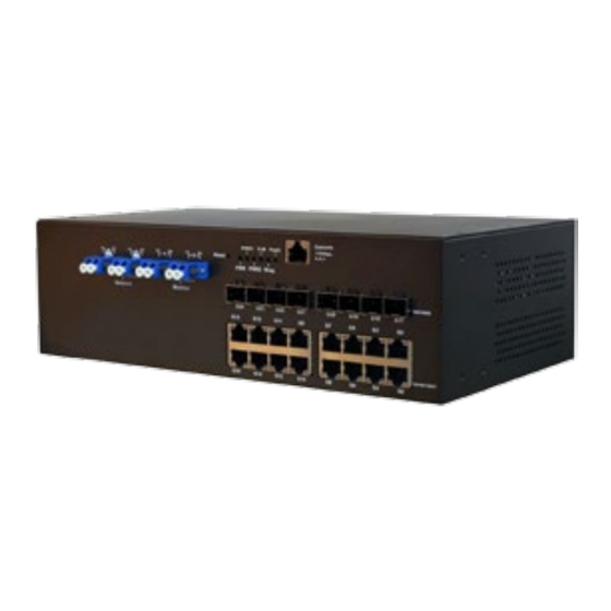
CNGE24MS-OB(M,S)
INDUSTRIAL 24-PORT ALL GIGABIT MANAGED ETHERNET SWITCH
WITH 16 TX PORTS AND 8 SFP PORTS PLUS OPTICAL BYPASS
The ComNet CNGE24MS-OB is a Managed Ethernet Switch with sixteen
10/100/1000 Mbps TX ports and eight 100/1000 Mbps SFP* ports that use
ComNet SFPs for fiber type, connector type and distance. This switch also
includes two sets of bypass ports that ensure network integrity during power
loss or maintenance. The CNGE24MS-OB is IEEE802.3-compliant and offers
multiple Ethernet redundancy protocols (ComRing, C-Ring, and MSTP/RSTP/
STP) which protect your applications from network interruptions or temporary
malfunctions by redirecting transmission within the network. Unlike most
Ethernet switches, these environmentally hardened units are designed for
deployment in difficult operating environments, and are available for use
with either conventional CAT-5e copper or optical transmission media.
Rev. 11.18.16
Advertisement
Table of Contents

Related Manuals for Comnet CNGE24MS-OB


Summary of Contents for Comnet CNGE24MS-OB
- Page 1 The ComNet CNGE24MS-OB is a Managed Ethernet Switch with sixteen 10/100/1000 Mbps TX ports and eight 100/1000 Mbps SFP* ports that use ComNet SFPs for fiber type, connector type and distance. This switch also includes two sets of bypass ports that ensure network integrity during power loss or maintenance.
-
Page 2: Table Of Contents
INSTALLATION AND OPERATION MANUAL CNGE24MS-OB(M,S) Contents Regulatory Compliance Statement Warranty Disclaimer Safety Information Overview Introduction Software Features Hardware Features Hardware Overview Front Panel Front Panel LEDs Rack-mount Installation Wiring Fault Relay AC Power Connection Cables Ethernet Cables Bypass Ports Console Cable... -
Page 3: Regulatory Compliance Statement
ComNet warrants that all ComNet products are free from defects in material and workmanship for a specified warranty period from the invoice date for the life of the installation. ComNet will repair or replace products found by ComNet to be defective within this warranty period, with shipment expenses apportioned by ComNet and the distributor. -
Page 4: Overview
Overview Introduction The CNGE24MS-OB(M,S) is powerful managed Ethernet switch that has many features. These switches can work under a wide temperature range, dusty environment and humidity condition They can be managed by Windows Utility, WEB, TELNET and Console or other third-party SNMP software as well. -
Page 5: Software Features
INSTALLATION AND OPERATION MANUAL CNGE24MS-OB(M,S) Software Features » Redundant Ethernet Ring (Recovery time < 30ms over 250 unit connection) » Supports Ring Coupling, Dual Homing, RSTP over Ring » Supports SNMPv1/v2c/v3 & RMON & Port base/IEEE 802.1Q VLAN Network Management »... -
Page 6: Hardware Overview
16 × 10/100/1000BASE-T(X) Console Use RS-232 with RJ-45 connector to manage switch. 2 3 4 5 6 7 11 12 13 CNGE24MS-OB(M,S) Front Panel 1. Fiber bypass ports 2. Power LED 3. Power 1 LED 4. Power 2 LED 5. Ring master LED 6. -
Page 7: Front Panel Leds
Gigabit SFP ports LNK/ACT Green Blinking Data transmitted. Port is Connected CNGE24MS-OB(M,S) Rear Panel 1. Power socket of power input for AC 100V~240V / 50~60Hz 2. Relay output to carry capacity of 1A at 24VDC INS_CNGE24MS-OB(M,S)_REV– TECH SUPPORT: 1.888.678.9427 09/12/12 PAGE 7... -
Page 8: Rack-Mount Installation
INSTALLATION AND OPERATION MANUAL CNGE24MS-OB(M,S) Rack-mount Installation The device comes with two mounting kits for you to install the device to a rack. Before installation, keep the following guidelines in mind. Elevated Operating Ambient: If installed in a closed environment, make sure the operating ambient temperature is compatible with the maximum ambient temperature (Tma) specified by the manufacturer. -
Page 9: Wiring
INSTALLATION AND OPERATION MANUAL CNGE24MS-OB(M,S) Step 1: Install the L-shape mounting kits provided in the package to the left and right of the device. Step 2: With front brackets orientated in front of the rack, mount the device in the rack with four rack-mounting screws. -
Page 10: Ac Power Connection
INSTALLATION AND OPERATION MANUAL CNGE24MS-OB(M,S) AC Power Connection For power supply, simply insert the AC power cable to the power connector at the back of the switch and turn on the power switch. The input voltage is 100V~240V / 50~60Hz. -
Page 11: Cables
Cables Ethernet Cables The CNGE24MS-OB(M,S) switch has standard Ethernet ports. According to the link type, the switch uses CAT3, CAT4, CAT5 or CAT5-e UTP cables to connect to any other network device (PCs, servers, switches, routers, or hubs). Please refer to the following table for cable specifications. - Page 12 BI_DD+ BI_DD- 1000 BASE-T RJ-45 Pin Assignments The CNGE24MS-OB(M,S) switch supports auto MDI/MDI-X operation. You can use a straight- through cable to connect a PC to the switch. The table below shows the 10/100BASE-T(X) MDI and MDI-X port pin outs.
-
Page 13: Bypass Ports
ComNet Bypass Switch PC1 Packet Bypass to PC2 The CNGE24MS-OB(M,S) provides two sets of bypass fiber ports, giving the SFP fiber ports addition redundancy capabilities. Connect a LC fiber cable from a fiber port to a monitor port on the front panel and another LC fiber cable from the corresponding network port to another switch. -
Page 14: Console Cable
Console Cable The CNGE24MS-OB(M,S) switch can be managed by the console port. The DB-9 to RJ-45 cable can be found in the package. You can connect them to the PC via a RS-232 cable with DB-9 female connector and the other end (RJ-45 connector) connects to console port of the switch. - Page 15 INSTALLATION AND OPERATION MANUAL CNGE24MS-OB(M,S) DB9 Male DB9 Female Male Connector Female Connector Received Line Signal Detect (Received by DTE Received Line Signal Detect (Transmitted Device) from DCE Device) Received Data (Received by DTE Device) Transmitted Data (Transmitted from DCE...
-
Page 16: Web Management
INSTALLATION AND OPERATION MANUAL CNGE24MS-OB(M,S) WEB Management Attention: While installing and upgrading firmware, please remove physical loop connection first. DO NOT power off equipment while the firmware is upgrading! Configuration by Web Browser This section details configuration through the Web browser. -
Page 17: Main Interface
INSTALLATION AND OPERATION MANUAL CNGE24MS-OB(M,S) Login screen Main Interface Main interface INS_CNGE24MS-OB(M,S)_REV– TECH SUPPORT: 1.888.678.9427 09/12/12 PAGE 17... - Page 18 INSTALLATION AND OPERATION MANUAL CNGE24MS-OB(M,S) Basic Setting System Information The switch system information is provided here. System Information interface Label Description System Contact The textual identification of the contact person for this managed node, together with information on how to contact this person. The allowed string length is 0 to 255, and the allowed content is the ASCII characters from 32 to 126.
- Page 19 INSTALLATION AND OPERATION MANUAL CNGE24MS-OB(M,S) Admin & Password This page allows you to configure the system password required to access the web pages or log in from the CLI. Label Description Old Password Enter the current system password. If this is incorrect, the new password will not be set.
-
Page 20: Authentication Method
INSTALLATION AND OPERATION MANUAL CNGE24MS-OB(M,S) Authentication Method This page allows you to configure how a user is authenticated when he logs into the switch via one of the management client interfaces. Label Description Client The management client for which the configuration below applies. - Page 21 INSTALLATION AND OPERATION MANUAL CNGE24MS-OB(M,S) IP Setting Configure the managed switch IP information on this page. Label Description DHCP Client Enable the DHCP client by checking this box. If DHCP fails and the configured IP address is zero, DHCP will retry. If DHCP fails and the configured IP address is non- zero, DHCP will stop and the configured IP settings will be used.
- Page 22 INSTALLATION AND OPERATION MANUAL CNGE24MS-OB(M,S) IPv6 Setting Configure the switch-management IPv6 information on this page. Label Description Auto Enable IPv6 auto-configuration by checking this box. If the system cannot obtain the Configuration stateless address in time, the configured IPv6 settings will be used. The router may delay responding to a router solicitation for a few seconds, the total time needed to complete auto-configuration can be significantly longer.
- Page 23 INSTALLATION AND OPERATION MANUAL CNGE24MS-OB(M,S) HTTPS Label Description Mode Indicates the HTTPS mode operation. Possible modes are: Enabled: Enable HTTPS mode operation. Disabled: Disable HTTPS mode operation. Save Select to save changes. Reset Select to undo any changes made locally and revert to previously saved values.
- Page 24 INSTALLATION AND OPERATION MANUAL CNGE24MS-OB(M,S) LLDP LLDP Parameters This page allows the user to inspect and configure the current LLDP port settings. Label Description Enabled The switch will send out LLDP information, and will analyze LLDP information received from neighbors.
- Page 25 INSTALLATION AND OPERATION MANUAL CNGE24MS-OB(M,S) LLDP Neighbor Information This page provides a status overview for all LLDP neighbors. The displayed table contains a row for each port on which an LLDP neighbor is detected. The columns hold the following information:...
- Page 26 INSTALLATION AND OPERATION MANUAL CNGE24MS-OB(M,S) LLDP Statistics This page provides an overview of all LLDP traffic. Two types of counters are shown. Global counters are counters that refer to the whole stack, switch, while local counters refer to counters for the currently selected switch.
- Page 27 INSTALLATION AND OPERATION MANUAL CNGE24MS-OB(M,S) Local Counters Label Description Local Port The port on which LLDP frames are received or transmitted. Tx Frames The number of LLDP frames transmitted on the port. Rx Frames The number of LLDP frames received on the port.
- Page 28 INSTALLATION AND OPERATION MANUAL CNGE24MS-OB(M,S) DHCP Server Setting The system provides with DHCP server function. Enable the DHCP server function, the switch system will be a DHCP server. DHCP Dynamic Client List When the DHCP server function is activated, the system will collect the DHCP client information and display in here.
-
Page 29: Port Setting
INSTALLATION AND OPERATION MANUAL CNGE24MS-OB(M,S) Port Setting Port Control This page displays current port configurations. Ports can also be configured here. INS_CNGE24MS-OB(M,S)_REV– TECH SUPPORT: 1.888.678.9427 09/12/12 PAGE 29... - Page 30 INSTALLATION AND OPERATION MANUAL CNGE24MS-OB(M,S) Label Description Port This is the logical port number for this row. Link The current link state is displayed graphically. Green indicates the link is up and red that it is down. Current Link Provides the current link speed of the port.
- Page 31 INSTALLATION AND OPERATION MANUAL CNGE24MS-OB(M,S) Port Trunk Trunk Configuration This page is used to configure the Aggregation hash mode and the aggregation group. Label Description Source MAC The Source MAC address can be used to calculate the destination port for the frame.
- Page 32 INSTALLATION AND OPERATION MANUAL CNGE24MS-OB(M,S) LACP Port Configuration This page allows the user to inspect the current LACP port configurations, and possibly change them as well. Label Description Port Indicates the group ID for the settings contained in the same row. Group ID “Normal”...
- Page 33 INSTALLATION AND OPERATION MANUAL CNGE24MS-OB(M,S) LACP System Status This page provides a status overview for all LACP instances. Label Description Aggr ID The Aggregation ID associated with this aggregation instance. For LLAG the id is shown as ‘isid:aggr-id’ and for GLAGs as ‘aggr-id’...
- Page 34 INSTALLATION AND OPERATION MANUAL CNGE24MS-OB(M,S) LACP Status This page provides a status overview for LACP status for all ports. Label Description Port The switch port number. LACP ‘Yes’ means that LACP is enabled and the port link is up. ‘No’ means that LACP is not enabled or that the port link is down.
- Page 35 INSTALLATION AND OPERATION MANUAL CNGE24MS-OB(M,S) LACP Statistics This page provides an overview for LACP statistics for all ports. Label Description Port The switch port number LACP TransmittedShows how many LACP frames have been sent from each port LACP Received Shows how many LACP frames have been received at each port.
- Page 36 INSTALLATION AND OPERATION MANUAL CNGE24MS-OB(M,S) Redundancy C-Ring C-Ring is the most powerful Ring in the world. The recovery time of C-Ring is less than 30ms. It can reduce unexpected damage caused by network topology change. C-Ring Supports 3 Ring topologies: C-Ring, Coupling Ring and Dual Homing.
- Page 37 INSTALLATION AND OPERATION MANUAL CNGE24MS-OB(M,S) Legacy Ring Legacy ring provides support for the switch to be used in an existing ring of ComNet X-Ring enabled switches. X-Ring provides a faster redundant recovery than Spanning Tree topology. The action is similar to STP or RSTP, but the algorithms between them are not the same.
- Page 38 INSTALLATION AND OPERATION MANUAL CNGE24MS-OB(M,S) MSTP Bridge Settings This page allows you to configure RSTP system settings. The settings are used by all RSTP Bridge instances in the Switch Stack. Label Description Protocol Version The STP protocol version setting. Valid values are STP, RSTP and MSTP.
- Page 39 INSTALLATION AND OPERATION MANUAL CNGE24MS-OB(M,S) MSTI Mapping This page allows the user to inspect the current STP MSTI bridge instance priority configurations, and possibly change them as well. Label Description Configuration The name identifying the VLAN to MSTI mapping. Bridges must share the name and...
- Page 40 INSTALLATION AND OPERATION MANUAL CNGE24MS-OB(M,S) MSTI Priorities This page allows the user to inspect the current STP MSTI bridge instance priority configurations, and possibly change them as well. Label Description MSTI The bridge instance. The CIST is the default instance, which is always active.
- Page 41 INSTALLATION AND OPERATION MANUAL CNGE24MS-OB(M,S) CIST Ports This page allows the user to inspect the current STP CIST port configurations, and possibly change them as well. This page contains settings for physical and aggregated ports. The aggregation settings are stack global.
- Page 42 INSTALLATION AND OPERATION MANUAL CNGE24MS-OB(M,S) Label Description Priority Controls the port priority. This can be used to control priority of ports having identical port cost. (See above). OpenEdge (state Operational flag describing whether the port is connecting directly to edge devices. (No flag) Bridges attached).
- Page 43 INSTALLATION AND OPERATION MANUAL CNGE24MS-OB(M,S) MSTI Ports This page allows the user to inspect the current STP MSTI port configurations, and possibly change them as well. A MSTI port is a virtual port, which is instantiated separately for each active CIST (physical) port for each MSTI instance configured and applicable for the port.
- Page 44 INSTALLATION AND OPERATION MANUAL CNGE24MS-OB(M,S) STP Bridges This page provides a status overview for all STP bridge instances. The displayed table contains a row for each STP bridge instance, where the column displays the following information: Label Description MSTI The Bridge Instance. This is also a link to the STP Detailed Bridge Status.
- Page 45 INSTALLATION AND OPERATION MANUAL CNGE24MS-OB(M,S) STP Port Status This page displays the STP CIST port status for port physical ports in the currently selected switch. Label Description Port The switch port number of the logical STP port. CIST Role The current STP port role of the CIST port. The port role can be one of the following values: AlternatePort BackupPort RootPort DesignatedPort.
- Page 46 INSTALLATION AND OPERATION MANUAL CNGE24MS-OB(M,S) STP Statistics This page displays the RSTP port statistics counters for bridge ports in the currently selected switch. Label Description Port The switch port number of the logical RSTP port. RSTP The number of RSTP Configuration BPDU’s received/transmitted on the port.
- Page 47 INSTALLATION AND OPERATION MANUAL CNGE24MS-OB(M,S) VLAN VLAN Membership Configuration The VLAN membership configuration for the selected stack switch unit switch can be monitored and modified here. Up to 64 VLANs are supported. This page allows for adding and deleting VLANs as well as adding and deleting port members of each VLAN.
-
Page 48: Vlan Port Configuration
INSTALLATION AND OPERATION MANUAL CNGE24MS-OB(M,S) VLAN Port Configuration INS_CNGE24MS-OB(M,S)_REV– TECH SUPPORT: 1.888.678.9427 09/12/12 PAGE 48... - Page 49 INSTALLATION AND OPERATION MANUAL CNGE24MS-OB(M,S) Label Description Ethertype for This field specifies the ether type used for Custom S-ports. This is a global setting for all customer S-Ports the Custom S-ports. Port This is the logical port number of this row.
- Page 50 INSTALLATION AND OPERATION MANUAL CNGE24MS-OB(M,S) How to use Unaware / C-Port / S-Port / S-Custom-Port Port can be one of the following types: Unaware, C-port, S-port, and S-custom-port. Ingress action Egress action Unaware When the port received untagged frames, an...
- Page 51 INSTALLATION AND OPERATION MANUAL CNGE24MS-OB(M,S) Packet Packet No VLAN No VLAN QinQ Packet Packet CNGE24MS-OB(M,S) VID: 5 VID: 5 Unaware VID: PVID TPID: 8100 TPID: 8100 TPID: 8100 Packet Packet VID: 5 Discarded TPID: 88A8 Packet Packet No VLAN No VLAN...
-
Page 52: Vlan Setting Example
INSTALLATION AND OPERATION MANUAL CNGE24MS-OB(M,S) VLAN Setting Example VLAN Access Mode Setting VLAN 10 VLAN 10 CNGE24MS-OB(M,S) CNGE24MS-OB(M,S) CNGE24MS-OB(M,S) Switch A Switch B Switch C VLAN Trunk VLAN Trunk 10,20 10,20 VLAN 20 VLAN 20 In the topology above, for Switch A,... - Page 53 INSTALLATION AND OPERATION MANUAL CNGE24MS-OB(M,S) VLAN 1Q Trunk mode VLAN 10 VLAN 10 CNGE24MS-OB(M,S) CNGE24MS-OB(M,S) CNGE24MS-OB(M,S) Switch A Switch B Switch C VLAN Trunk VLAN Trunk 10,20 10,20 VLAN 20 VLAN 20 In the topology above, for Switch B, Port 1 = VLAN 1Qtrunk mode = tagged 10,20...
-
Page 54: Vlan Qinq Mode
INSTALLATION AND OPERATION MANUAL CNGE24MS-OB(M,S) VLAN Hybrid mode To set Port 1 VLAN Hybrid mode = untagged 10 Tagged 10,20 Configure the VLAN for the Switch as shown VLAN QinQ mode Below is an example of the VLAN QinQ Mode, which is typically used in an environment with unknown VLAN. - Page 55 INSTALLATION AND OPERATION MANUAL CNGE24MS-OB(M,S) VLAN Management VLAN ID Setting If Management VLAN is set, only the same VLAN ID port can control the switch. INS_CNGE24MS-OB(M,S)_REV– TECH SUPPORT: 1.888.678.9427 09/12/12 PAGE 55...
- Page 56 INSTALLATION AND OPERATION MANUAL CNGE24MS-OB(M,S) Private VLAN The Private VLAN membership configurations for the switch can be monitored and modified here. Private VLANs can be added or deleted here. Port members of each Private VLAN can be added or removed here. Private VLANs are based on the source port mask, and there are no connections to VLANs.
- Page 57 INSTALLATION AND OPERATION MANUAL CNGE24MS-OB(M,S) Label Description Port Members A check box is provided for each port of a private VLAN. When checked, port isolation is enabled for that port. When unchecked, port isolation is disabled for that port. By default, port isolation is disabled for all ports.
- Page 58 INSTALLATION AND OPERATION MANUAL CNGE24MS-OB(M,S) SNMP SNMP-System Label Description Mode Indicates the SNMP mode operation. Possible modes are: Enabled: Enable SNMP mode operation. SNMP v2c: Set SNMP supported version 2c. Disabled: Disable SNMP mode operation. Version Indicates the SNMP supported version. Possible versions are: SNMP v1: Set SNMP supported version 1.
- Page 59 INSTALLATION AND OPERATION MANUAL CNGE24MS-OB(M,S) Label Description Trap Mode Indicates the SNMP trap mode operation. Possible modes are: Enabled: Enable SNMP trap mode operation. Disabled: Disable SNMP trap mode operation. Trap Version Indicates the SNMP trap supported version. Possible versions are: SNMP v1: Set SNMP trap supported version 1.
- Page 60 INSTALLATION AND OPERATION MANUAL CNGE24MS-OB(M,S) Label Description Trap Inform Retry Indicates the SNMP trap inform retry times. The allowed range is 0 to 255. Times Trap Probe Indicates the SNMP trap probe security engine ID mode of operation. Possible values...
- Page 61 INSTALLATION AND OPERATION MANUAL CNGE24MS-OB(M,S) SNMP-Users Configure SNMPv3 users table on this page. The entry index keys are Engine ID and User Name. Label Description Delete Check to delete the entry. It will be deleted during the next save. Engine ID An octet string identifying the engine ID that this entry should belong to.
- Page 62 INSTALLATION AND OPERATION MANUAL CNGE24MS-OB(M,S) SNMP-Groups Configure SNMPv3 groups table on this page. The entry index keys are Security Model and Security Name. Label Description Delete Check to delete the entry. It will be deleted during the next save. Security Model Indicates the security model that this entry should belong to.
- Page 63 INSTALLATION AND OPERATION MANUAL CNGE24MS-OB(M,S) SNMP-Views Configure SNMPv3 views table on this page. The entry index keys are View Name and OID Subtree. Label Description Delete Check to delete the entry. It will be deleted during the next save. View Name A string identifying the view name that this entry should belong to.
- Page 64 INSTALLATION AND OPERATION MANUAL CNGE24MS-OB(M,S) SNMP-Accesses Configure SNMPv3 accesses table on this page. The entry index keys are Group Name, Security Model and Security Level. Label Description Delete Check to delete the entry. It will be deleted during the next save.
- Page 65 INSTALLATION AND OPERATION MANUAL CNGE24MS-OB(M,S) Traffic Prioritization Storm Control There is a unicast storm rate control, multicast storm rate control, and a broadcast storm rate control. These only affect flooded frames, i.e. frames with a (VLAN ID, DMAC) pair not present on the MAC Address table.
- Page 66 INSTALLATION AND OPERATION MANUAL CNGE24MS-OB(M,S) Port Classification QoS is an acronym for Quality of Service. It is a method to guarantee a bandwidth relationship between individual applications or protocols. Label Description Port The port number for which the configuration below applies QoS Class Controls the default QoS class.
- Page 67 INSTALLATION AND OPERATION MANUAL CNGE24MS-OB(M,S) Label Description DP level Controls the default Drop Precedence Level. All frames are classified to a DP level. If the port is VLAN aware and the frame is tagged, then the frame is classified to a DP level that is equal to the DEI value in the tag.
- Page 68 INSTALLATION AND OPERATION MANUAL CNGE24MS-OB(M,S) Port Tag Remarking This page provides an overview of QoS Egress Port Tag Remarking for all switch ports. Label Description Port The logical port for the settings contained in the same row. Click on the port number in order to configure tag remarking Mode Shows the tag remarking mode for this port.
- Page 69 INSTALLATION AND OPERATION MANUAL CNGE24MS-OB(M,S) Port DSCP This page allows you to configure the basic QoS Port DSCP Configuration settings for all switch ports. Label Description Port The Port column shows the list of ports for which you can configure dscp ingress and egress settings.
- Page 70 INSTALLATION AND OPERATION MANUAL CNGE24MS-OB(M,S) This page allows you to configure the Policer settings for all switch ports. Label Description Port The port number for which the configuration below applies Enable Controls whether the policer is enabled on this switch port.
- Page 71 INSTALLATION AND OPERATION MANUAL CNGE24MS-OB(M,S) Queue Policing This page allows you to configure the Queue Policer settings for all switch ports. Label Description Port The port number for which the configuration below applies. Enable(E) Controls whether the queue policer is enabled on this queue.
- Page 72 INSTALLATION AND OPERATION MANUAL CNGE24MS-OB(M,S) Port Shaping This page provides an overview of QoS Egress Port Shapers for all switch ports. Label Description Port The logical port for the settings contained in the same row. Click on the port number in order to configure the shapers.
- Page 73 INSTALLATION AND OPERATION MANUAL CNGE24MS-OB(M,S) DSCP Translation This page allows you to configure the basic QoS DSCP Translation settings for all switches. DSCP translation can be done in Ingress or Egress. Label Description DSCP Maximum number of supported DSCP values are 64 and valid DSCP value ranges from 0 to 63.
-
Page 74: Dscp Classification
INSTALLATION AND OPERATION MANUAL CNGE24MS-OB(M,S) DSCP Classification This page allows you to configure the mapping of QoS class and Drop Precedence Level to DSCP value. Label Description QoS Class Actual QoS class Actual Drop Precedence Level. DSCP Select the classified DSCP value (0-63). - Page 75 INSTALLATION AND OPERATION MANUAL CNGE24MS-OB(M,S) QoS Control List This page allows to edit|insert a single QoS Control Entry at a time. A QCE consists of several parameters. These parameters vary according to the frame type that you select. Label Description Port Members Check the checkbox button to include the port in the QCL entry.
- Page 76 INSTALLATION AND OPERATION MANUAL CNGE24MS-OB(M,S) Label Description 1. Any Allow all types of frames. 2. Ethernet Ethernet Type Valid Ethernet type can have a value within 0x600-0xFFFF or ‘Any’ but excluding 0x800(IPv4) and 0x86DD(IPv6), default value is ‘Any’. 3. LLC SSAP Address Valid SSAP(Source Service Access Point) can vary from 0x00 to 0xFF or ‘Any’, the default value is ‘Any’.
- Page 77 INSTALLATION AND OPERATION MANUAL CNGE24MS-OB(M,S) QoS Counters This page provides statistics for the different queues for all switch ports. Label Description Port The logical port for the settings contained in the same row. There are 8 QoS queues per port. Q0 is the lowest priority queue.
- Page 78 INSTALLATION AND OPERATION MANUAL CNGE24MS-OB(M,S) QCL Status This page shows the QCL status by different QCL users. Each row describes the QCE that is defined. It is a conflict if a specific QCE is not applied to the hardware due to hardware limitations.
- Page 79 INSTALLATION AND OPERATION MANUAL CNGE24MS-OB(M,S) IGMP Snooping This page provides IGMP Snooping related configuration. Label Description Snooping Enable the Global IGMP Snooping. Enabled Unregistered Enable unregistered IPMC traffic flooding. IPMC Flooding enabled Router Port Specify which ports act as router ports. A router port is a port on the Ethernet switch that leads towards the Layer 3 multicast device or IGMP query.
- Page 80 INSTALLATION AND OPERATION MANUAL CNGE24MS-OB(M,S) IGMP Snooping- VLAN Configuration- Each page shows up to 99 entries from the VLAN table, default being 20, selected through the “entries per page” input field. When first visited, the web page will show the first 20 entries from the beginning of the VLAN Table.
- Page 81 INSTALLATION AND OPERATION MANUAL CNGE24MS-OB(M,S) IGMP Snooping Status Label Description VLAN ID The VLAN ID of the entry. Querier Version The current working Querier version. Host Version The current working Host version. Querier Status Show the Querier status is “ACTIVE” or “IDLE”.
- Page 82 INSTALLATION AND OPERATION MANUAL CNGE24MS-OB(M,S) IGMP Snooping Groups Information Entries in the IGMP Group Table are shown on this page. The IGMP Group Table is sorted first by VLAN ID, and then by group. Label Description VLAN ID VLAN ID of the group.
- Page 83 INSTALLATION AND OPERATION MANUAL CNGE24MS-OB(M,S) Security Configure the ACL parameters (ACE) of each switch port. These parameters will affect frames received on a port unless the frame matches a specific ACE. Label Description Port The logical port for the settings contained in the same row.
- Page 84 INSTALLATION AND OPERATION MANUAL CNGE24MS-OB(M,S) Rate Limiters Configure the rate limiter for the ACL of the switch. Label Description Rate Limiter ID The rate limiter ID for the settings contained in the same row. Rate The rate unit is packet per second (pps), configure the rate as 1, 2, 4, 8, 16, 32, 64, 128, 256, 512, 1K, 2K, 4K, 8K, 16K, 32K, 64K, 128K, 256K, 512K, or 1024K.
- Page 85 INSTALLATION AND OPERATION MANUAL CNGE24MS-OB(M,S) ACL Control List Configure an ACE (Access Control Entry) on this page. An ACE consists of several parameters. These parameters vary according to the frame type that you select. First select the ingress port for the ACE, and then select the frame type. Different parameter options are displayed depending on the frame type that you selected.
- Page 86 INSTALLATION AND OPERATION MANUAL CNGE24MS-OB(M,S) Label Description SMAC Filter (Only displayed when the frame type is Ethernet Type or ARP.) Specify the source MAC filter for this ACE. Any: No SMAC filter is specified. (SMAC filter status is “don’t-care”.) Specific: If you want to filter a specific source MAC address with this ACE, choose this value.
- Page 87 INSTALLATION AND OPERATION MANUAL CNGE24MS-OB(M,S) Label Description VLAN ID Filter Specify the VLAN ID filter for this ACE. Any: No VLAN ID filter is specified. (VLAN ID filter status is “don’t-care”.) Specific: If you want to filter a specific VLAN ID with this ACE, choose this value. A field for entering a VLAN ID number appears.
- Page 88 INSTALLATION AND OPERATION MANUAL CNGE24MS-OB(M,S) Label Description IP Protocol Filter Specify the IP protocol filter for this ACE. Any: No IP protocol filter is specified (“don’t-care”). Specific: If you want to filter a specific IP protocol filter with this ACE, choose this value.
- Page 89 INSTALLATION AND OPERATION MANUAL CNGE24MS-OB(M,S) Label Description SIP Filter Specify the source IP filter for this ACE. Any: No source IP filter is specified. (Source IP filter is “don’t-care”.) Host: Source IP filter is set to Host. Specify the source IP address in the SIP Address field that appears.
- Page 90 INSTALLATION AND OPERATION MANUAL CNGE24MS-OB(M,S) Label Description ARP/RARP Specify the available ARP/RARP opcode (OP) flag for this ACE. Any: No ARP/RARP OP flag is specified. (OP is “don’t-care”.) ARP: Frame must have ARP/RARP opcode set to ARP. RARP: Frame must have ARP/RARP opcode set to RARP.
- Page 91 INSTALLATION AND OPERATION MANUAL CNGE24MS-OB(M,S) Label Description RARP SMAC Specify whether frames can hit the action according to their target hardware address Match field (THA) settings. 0: RARP frames where THA is not equal to the SMAC address. 1: RARP frames where THA is equal to the SMAC address.
- Page 92 INSTALLATION AND OPERATION MANUAL CNGE24MS-OB(M,S) Label Description TCP/UDP Source Specify the TCP/UDP source filter for this ACE. Filter Any: No TCP/UDP source filter is specified (TCP/UDP source filter status is “don’t-care”). Specific: If you want to filter a specific TCP/UDP source filter with this ACE, you can enter a specific TCP/UDP source value.
- Page 93 INSTALLATION AND OPERATION MANUAL CNGE24MS-OB(M,S) Label Description TCP SYN Specify the TCP “Synchronize sequence numbers” (SYN) value for this ACE. 0: TCP frames where the SYN field is set must not be able to match this entry. 1: TCP frames where the SYN field is set must be able to match this entry.
- Page 94 INSTALLATION AND OPERATION MANUAL CNGE24MS-OB(M,S) RADIUS Authentication Server Configuration The table has one row for each RADIUS Authentication Server and a number of columns, which are: Label Description The RADIUS Authentication Server number for which the configuration below applies. Enabled Enable the RADIUS Authentication Server by checking this box.
- Page 95 INSTALLATION AND OPERATION MANUAL CNGE24MS-OB(M,S) RADIUS Overview This page provides an overview of the status of the RADIUS servers configurable on the Authentication configuration page. RADIUS Authentication Servers Label Description The RADIUS server number. Click to navigate to detailed statistics for this server.
- Page 96 INSTALLATION AND OPERATION MANUAL CNGE24MS-OB(M,S) RADIUS Accounting Servers Label Description The RADIUS server number. Click to navigate to detailed statistics for this server. IP Address The IP address and UDP port number (in <IP Address>:<UDP Port> notation) of this server.
- Page 97 INSTALLATION AND OPERATION MANUAL CNGE24MS-OB(M,S) RADIUS Details The statistics map closely to those specified in RFC4668 – RADIUS Authentication Client MIB. Use the server select box to switch between the backend servers to show details for. The statistics map closely to those specified in RFC4668 – RADIUS Authentication Client MIB.
- Page 98 INSTALLATION AND OPERATION MANUAL CNGE24MS-OB(M,S) Label Description Packet Counters RADIUS accounting server packet counter. There are five receive and four transmit counters. Other Info This section contains information about the state of the server and the latest INS_CNGE24MS-OB(M,S)_REV– TECH SUPPORT: 1.888.678.9427...
- Page 99 INSTALLATION AND OPERATION MANUAL CNGE24MS-OB(M,S) NAS(802.1x) This page allows you to configure the IEEE 802.1X and MAC-based authentication system and port settings. The IEEE 802.1X standard defines a port-based access control procedure that prevents unauthorized access to a network by requiring users to first submit credentials for authentication.
- Page 100 INSTALLATION AND OPERATION MANUAL CNGE24MS-OB(M,S) Overview of MAC-Based Authentication Unlike 802.1X, MAC-based authentication is not a standard, but merely a best-practices method adopted by the industry. In MAC-based authentication, users are called clients, and the switch acts as the supplicant on behalf of clients. The initial frame (any kind of frame) sent by a client is snooped by the switch, which in turn uses the client’s MAC address as both username and...
- Page 101 INSTALLATION AND OPERATION MANUAL CNGE24MS-OB(M,S) Label Description Mode Indicates if 802.1X and MAC-based authentication is globally enabled or disabled on the switch. If globally disabled, all ports are allowed forwarding of frames. Reauthentication If checked, clients are reauthenticated after the interval specified by the Enabled Reauthentication Period.
- Page 102 INSTALLATION AND OPERATION MANUAL CNGE24MS-OB(M,S) Label Description Admin State If NAS is globally enabled, this selection controls the port’s authentication mode. The following modes are available: Force Authorized In this mode, the switch will send one EAPOL Success frame when the port link comes up, and any client on the port will be allowed network access without authentication.
- Page 103 INSTALLATION AND OPERATION MANUAL CNGE24MS-OB(M,S) Label Description Port State The current state of the port. It can undertake one of the following values: Globally Disabled: NAS is globally disabled. Link Down: NAS is globally enabled, but there is no link on the port.
- Page 104 INSTALLATION AND OPERATION MANUAL CNGE24MS-OB(M,S) Label Description Last ID The user name (supplicant identity) carried in the most recently received Response Identity EAPOL frame for EAPOL-based authentication, and the source MAC address from the most recently received frame from a new client for MAC-based authentication.
- Page 105 INSTALLATION AND OPERATION MANUAL CNGE24MS-OB(M,S) Label Description Backend Server These backend (RADIUS) frame counters are available for the following administrative Counters states: • 802.1X • MAC-based Auth. Last Supplicant/ Information about the last supplicant/client that attempted to authenticate. This Client Info information is available for the following administrative states: •...
- Page 106 INSTALLATION AND OPERATION MANUAL CNGE24MS-OB(M,S) Warning Fault Alarm When any selected fault event is happened, the Fault LED in switch panel will light up and the electric relay will signal at the same time. The following table describes the labels in this screen.
- Page 107 INSTALLATION AND OPERATION MANUAL CNGE24MS-OB(M,S) System Warning SYSLOG Setting The SYSLOG is a protocol to transmit event notification messages across networks. Please refer to RFC 3164 – The BSD SYSLOG Protocol System Warning – SYSLOG Setting interface The following table describes the labels in this screen.
- Page 108 INSTALLATION AND OPERATION MANUAL CNGE24MS-OB(M,S) Event Selection SYSLOG is the warning method supported by the system. Check the corresponding box to enable system event warning method you wish to choose. Please note that the checkbox cannot be checked when SYSLOG is disabled.
- Page 109 INSTALLATION AND OPERATION MANUAL CNGE24MS-OB(M,S) Monitor and Diag MAC Table The MAC Address Table is configured on this page. Set timeouts for entries in the dynamic MAC Table and configure the static MAC table here. Aging Configuration By default, dynamic entries are removed from the MAC after 300 seconds. This removal is also called aging.
- Page 110 INSTALLATION AND OPERATION MANUAL CNGE24MS-OB(M,S) MAC Table Learning If the learning mode for a given port is grayed out, another module is in control of the mode, so that it cannot be changed by the user. An example of such a module is the MAC-Based Authentication under 802.1X.
- Page 111 INSTALLATION AND OPERATION MANUAL CNGE24MS-OB(M,S) MAC Table Each page shows up to 999 entries from the MAC table, default being 20, selected through the “entries per page” input field. When first visited, the web page will show the first 20 entries from the beginning of the MAC Table.
- Page 112 INSTALLATION AND OPERATION MANUAL CNGE24MS-OB(M,S) Traffic Overview This page provides an overview of general traffic statistics for all switch ports. Label Description Port The logical port for the settings contained in the same row. Packets The number of received and transmitted packets per port.
- Page 113 INSTALLATION AND OPERATION MANUAL CNGE24MS-OB(M,S) Detailed Statistics-Receive & Transmit Total Label Description Rx and Tx Packets The number of received and transmitted (good and bad) packets. Rx and Tx Octets The number of received and transmitted (good and bad) bytes. Includes FCS, but excludes framing bits.
- Page 114 INSTALLATION AND OPERATION MANUAL CNGE24MS-OB(M,S) Label Description Tx Drops The number of frames dropped due to output buffer congestion. Tx Late / Exc.Coll. The number of frames dropped due to excessive or late collisions. Short frames are frames that are smaller than 64 bytes.
- Page 115 INSTALLATION AND OPERATION MANUAL CNGE24MS-OB(M,S) Port Monitoring Configure port Mirroring on this page. To debug network problems, selected traffic can be copied, or mirrored, to a mirror port where a frame analyzer can be attached to analyze the frame flow.
- Page 116 INSTALLATION AND OPERATION MANUAL CNGE24MS-OB(M,S) System Log Information The switch system log information is provided here. Label Description The ID (>= 1) of the system log entry. Level The level of the system log entry. The following level types are supported: Info: Information level of the system log.
- Page 117 INSTALLATION AND OPERATION MANUAL CNGE24MS-OB(M,S) VeriPHY This page is used for running the VeriPHY Cable Diagnostics. Press Start to run the diagnostics. This will take approximately 5 seconds. If all ports are selected, this can take approximately 15 seconds. When completed, the page refreshes automatically, and you can view the cable diagnostics results in the cable status table.
- Page 118 INSTALLATION AND OPERATION MANUAL CNGE24MS-OB(M,S) SFP Monitor The DDM function allows an SFP module which supports DDM function, measure the temperature of the apparatus along with other information. INS_CNGE24MS-OB(M,S)_REV– TECH SUPPORT: 1.888.678.9427 09/12/12 PAGE 118...
- Page 119 INSTALLATION AND OPERATION MANUAL CNGE24MS-OB(M,S) Ping This page allows you to issue ICMP PING packets to troubleshoot IP connectivity issues. After you press Start, 5 ICMP packets are transmitted, and the sequence number and roundtrip time are displayed upon reception of a reply. The page refreshes automatically until responses to all packets are received, or until a timeout occurs.
- Page 120 INSTALLATION AND OPERATION MANUAL CNGE24MS-OB(M,S) IPv6 Ping PING6 server ::192.168.10.1 sendto sendto sendto sendto sendto Sent 5 packets, received 0 OK, 0 bad INS_CNGE24MS-OB(M,S)_REV– TECH SUPPORT: 1.888.678.9427 09/12/12 PAGE 120...
- Page 121 INSTALLATION AND OPERATION MANUAL CNGE24MS-OB(M,S) Synchronization-PTP This page allows the user to configure and inspect the current PTP clock settings. Label Description One_pps_mode This Selection box will allow you to select the One_pps_mode configuration. The following values are possible: 1. Output : Enable the 1 pps clock output 2.
- Page 122 INSTALLATION AND OPERATION MANUAL CNGE24MS-OB(M,S) Label Description Delete Check this box and click on ‘Save’ to delete the clock instance. Clock Instance Indicates the Instance of a particular Clock Instance [0..3]. Click on the Clock Instance number to edit the Clock details.
- Page 123 INSTALLATION AND OPERATION MANUAL CNGE24MS-OB(M,S) System Reboot You can reset the stack switch on this page. After reset, the system will boot normally as if you had powered-on the devices Label Description Select to reboot device. Select to return to the Port State page without rebooting.
-
Page 124: Command Line Interface Management
CNGE24MS-OB(M,S) Command Line Interface Management About CLI Management Besides WEB-base management, CNGE24MS-OB(M,S) also support CLI management. You can use console or telnet to management switch by CLI. CLI Management by RS-232 Serial Console (115200, 8, none, 1, none) Before Configuring by RS-232 serial console, use an RJ45 to DB9-F cable to connect the Switches’... - Page 125 INSTALLATION AND OPERATION MANUAL CNGE24MS-OB(M,S) Step 2. Input a name for new connection Step 3. Select the COM port number INS_CNGE24MS-OB(M,S)_REV– TECH SUPPORT: 1.888.678.9427 09/12/12 PAGE 125...
- Page 126 INSTALLATION AND OPERATION MANUAL CNGE24MS-OB(M,S) Step 4. The COM port properties setting, 115200 for Bits per second, 8 for Data bits, None for Parity, 1 for Stop bits and none for Flow control. Step 5. The Console login screen will appear. Use the keyboard to enter the Username and Password (The same with the password for Web Browser), then press Enter.
- Page 127 INSTALLATION AND OPERATION MANUAL CNGE24MS-OB(M,S) CLI Management by Telnet Users can use “TELNET” to configure the switches. The default value is as below: IP Address: 192.168.10.1 Subnet Mask: 255.255.255.0 Default Gateway: 192.168.10.254 User Name: admin Password: admin Follow the steps below to access the console via Telnet.
- Page 128 INSTALLATION AND OPERATION MANUAL CNGE24MS-OB(M,S) Command Sets System Configuration [all] [<port_list>] Reboot Restore Default [keep_ip] Contact [<contact>] Name [<name>] System> Location [<location>] Description [<description>] Password <password> Username [<username>] Timezone [<offset>] Log [<log_id>] [all|info|warning|error] [clear] Configuration DHCP [enable|disable] IP> Setup [<ip_addr>] [<ip_mask>] [<ip_router>] [<vid>] Ping <ip_addr_string>...
- Page 129 INSTALLATION AND OPERATION MANUAL CNGE24MS-OB(M,S) Configuration [<port_list>] Add <mac_addr> <port_list> [<vid>] Delete <mac_addr> [<vid>] Lookup <mac_addr> [<vid>] MAC> Agetime [<age_time>] Learning [<port_list>] [auto|disable|secure] Dump [<mac_max>] [<mac_addr>] [<vid>] Statistics [<port_list>] Flush VLAN Configuration [<port_list>] PVID [<port_list>] [<vid>|none] FrameType [<port_list>] [all|tagged|untagged] IngressFilter [<port_list>] [enable|disable] tx_tag [<port_list>] [untag_pvid|untag_all|tag_all]...
- Page 130 INSTALLATION AND OPERATION MANUAL CNGE24MS-OB(M,S) Security Switch Switch security setting Security> Network Network security setting Authentication, Authorization and Accounting setting Security Switch Password <password> Auth Authentication Security/switch> Secure Shell HTTPS Hypertext Transfer Protocol over Secure Socket Layer RMON Remote Network Monitoring...
- Page 131 INSTALLATION AND OPERATION MANUAL CNGE24MS-OB(M,S) Security Network Psec Port Security Status Network Access Server (IEEE 802.1X) Security/Network> Access Control List DHCP Dynamic Host Configuration Protocol Security Network Psec Switch [<port_list>] Security/Network/Psec> Port [<port_list>] Security Network NAS Configuration [<port_list>] Mode [enable|disable] State [<port_list>] [auto|authorized|unauthorized|macbased]...
- Page 132 INSTALLATION AND OPERATION MANUAL CNGE24MS-OB(M,S) Security Network ACL Configuration [<port_list>] Action [<port_list>] [permit|deny] [<rate_limiter>][<port_redirect>] [<mirror>] [<logging>] [<shutdown>] Policy [<port_list>] [<policy>] Rate [<rate_limiter_list>] [<rate_unit>] [<rate>] Add [<ace_id>] [<ace_id_next>][(port <port_list>)] [(policy <policy> <policy_ bitmask>)][<tagged>] [<vid>] [<tag_prio>] [<dmac_type>][(etype [<etype>] [<smac>] [<dmac>]) | (arp [<sip>] [<dip>] [<smac>] [<arp_opcode>] [<arp_flags>]) | (ip [<sip>] [<dip>] [<protocol>] [<ip_flags>]) |...
- Page 133 INSTALLATION AND OPERATION MANUAL CNGE24MS-OB(M,S) Configuration Version [<stp_version>] Non-certified release, v Txhold [<holdcount>]lt 15:15:15, Dec 6 2007 MaxAge [<max_age>] FwdDelay [<delay>] bpduFilter [enable|disable] bpduGuard [enable|disable] recovery [<timeout>] CName [<config-name>] [<integer>] Status [<msti>] [<port_list>] Msti Priority [<msti>] [<priority>] Msti Map [<msti>] [clear] Msti Add <msti>...
- Page 134 INSTALLATION AND OPERATION MANUAL CNGE24MS-OB(M,S) LACP Configuration [<port_list>] Mode [<port_list>] [enable|disable] Key [<port_list>] [<key>] LACP> Role [<port_list>] [active|passive] Status [<port_list>] Statistics [<port_list>] [clear] LLDP Configuration [<port_list>] Mode [<port_list>] [enable|disable] LLDP> Statistics [<port_list>] [clear] Info [<port_list>] DSCP Map [<dscp_list>] [<class>] [<dpl>] DSCP Translation [<dscp_list>] [<trans_dscp>]...
- Page 135 INSTALLATION AND OPERATION MANUAL CNGE24MS-OB(M,S) Mirror Configuration [<port_list>] Mirror> Port [<port>|disable] Mode [<port_list>] [enable|disable|rx|tx] Dot1x Configuration [<port_list>] Mode [enable|disable] State [<port_list>] [macbased|auto|authorized|unauthorized] Authenticate [<port_list>] [now] Reauthentication [enable|disable] Dot1x> Period [<reauth_period>] Timeout [<eapol_timeout>] Statistics [<port_list>] [clear|eapol|radius] Clients [<port_list>] [all|<client_cnt>] Agetime [<age_time>] Holdtime [<hold_time>]...
- Page 136 INSTALLATION AND OPERATION MANUAL CNGE24MS-OB(M,S) Configuration [<port_list>] Action [<port_list>] [permit|deny] [<rate_limiter>] [<port_copy>] [<logging>] [<shutdown>] Policy [<port_list>] [<policy>] Rate [<rate_limiter_list>] [<packet_rate>] Add [<ace_id>] [<ace_id_next>] [switch | (port <port>) | (policy <policy>)] [<vid>] [<tag_prio>] [<dmac_type>] [(etype [<etype>] [<smac>] [<dmac>]) | ACL> (arp [<sip>] [<dip>] [<smac>] [<arp_opcode>] [<arp_flags>]) | (ip [<sip>] [<dip>] [<protocol>] [<ip_flags>]) |...
- Page 137 INSTALLATION AND OPERATION MANUAL CNGE24MS-OB(M,S) SNMP Trap Inform Retry Times [<retries>] Trap Probe Security Engine ID [enable|disable] Trap Security Engine ID [<engineid>] Trap Security Name [<security_name>] Engine ID [<engineid>] Community Add <community> [<ip_addr>] [<ip_mask>] Community Delete <index> Community Lookup [<index>] User Add <engineid>...
- Page 138 INSTALLATION AND OPERATION MANUAL CNGE24MS-OB(M,S) Configuration [<clockinst>] PortState <clockinst> [<port_list>] [enable|disable|internal] ClockCreate <clockinst> [<devtype>] [<twostep>] [<protocol>] [<oneway>] [<clockid>] [<tag_enable>] [<vid>] [<prio>] ClockDelete <clockinst> [<devtype>] DefaultDS <clockinst> [<priority1>] [<priority2>] [<domain>] CurrentDS <clockinst> ParentDS <clockinst> Timingproperties <clockinst> [<utcoffset>] [<valid>] [<leap59>] [<leap61>] [<timetrac>] [<freqtrac>] [<ptptimescale>] [<timesource>]...
- Page 139 INSTALLATION AND OPERATION MANUAL CNGE24MS-OB(M,S) IPMC Configuration [igmp] Mode [igmp] [enable|disable] Flooding [igmp] [enable|disable] VLAN Add [igmp] <vid> VLAN Delete [igmp] <vid> State [igmp] [<vid>] [enable|disable] IPMC> Querier [igmp] [<vid>] [enable|disable] Fastleave [igmp] [<port_list>] [enable|disable] Router [igmp] [<port_list>] [enable|disable] Status [igmp] [<vid>] Groups [igmp] [<vid>]...
- Page 140 INSTALLATION AND OPERATION MANUAL CNGE24MS-OB(M,S) Event Configuration Syslog SystemStart [enable|disable] Syslog PowerStatus [enable|disable] Syslog SnmpAuthenticationFailure [enable|disable] Syslog RingTopologyChange [enable|disable] Event> Syslog Port [<port_list>] [disable|linkup|linkdown|both] SMTP SystemStart [enable|disable] SMTP PowerStatus [enable|disable] SMTP SnmpAuthenticationFailure [enable|disable] SMTP RingTopologyChange [enable|disable] SMTP Port [<port_list>] [disable|linkup|linkdown|both]...
- Page 141 INSTALLATION AND OPERATION MANUAL CNGE24MS-OB(M,S) DeviceBinding Mode [enable|disable] Port Mode [<port_list>] [disable|scan|binding|shutdown] Port DDOS Mode [<port_list>] [enable|disable] Port DDOS Sensibility [<port_list>] [low|normal|medium|high] Port DDOS Packet [<port_list>] [rx_total|rx_unicast|rx_multicast|rx_broadcast|tcp|udp] Port DDOS Low [<port_list>] [<socket_number>] Port DDOS High [<port_list>] [<socket_number>] Port DDOS Filter [<port_list>] [source|destination] Port DDOS Action [<port_list>] [do_nothing|block_1_min|block_10_mins|...
-
Page 142: Technical Specifications
INSTALLATION AND OPERATION MANUAL CNGE24MS-OB(M,S) Technical Specifications Physical Ports 10/100/1000Base-T(X) 16 Ports in RJ45 Auto MDI/MDIX 100/1000Base-X 8 SFP port LC Bypass 4 in Simplex mode, 2 in Duplex Mode Multimode or Single Mode, dependent on model selection Technology Ethernet Standards IEEE 802.3 for 10Base-T... - Page 143 INSTALLATION AND OPERATION MANUAL CNGE24MS-OB(M,S) Software Features STP/RSTP/MSTP (IEEE 802.1D/w/s) Redundant Ring (C-Ring) with recovery time less than 30ms over 250 units TOS/Diffserv supported Quality of Service (802.1p) for real-time traffic VLAN (802.1Q) with VLAN tagging and GVRP supported IGMP Snooping...
- Page 144 8 TURNBERRY PARK ROAD | GILDERSOME | MORLEY | LEEDS, UK LS27 7LE T: +44 (0)113 307 6400 | F: +44 (0)113 253 7462 | INFO-EUROPE@COMNET.NET © 2016 Communications Networks Corporation. All Rights Reserved. “ComNet” and the “ComNet Logo” are registered trademarks of Communication Networks, LLC.
Need help?
Do you have a question about the CNGE24MS-OB and is the answer not in the manual?
Questions and answers