Table of Contents
Advertisement
Quick Links
This manual serves the following
ComNet Model Numbers:
CNGE20FX4TX16MS
INSTALLATION AND OPERATION MANUAL
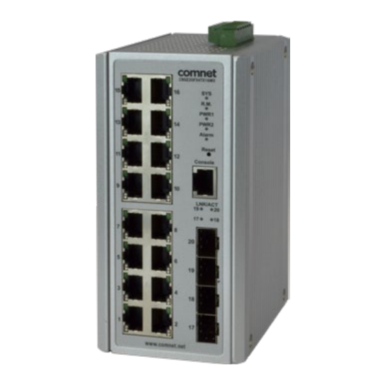
CNGE20FX4TX16MS
All Gigabit Managed Ethernet Switch
with (16) 10/100/1000TX + (4) 100/1000FX SFP Ports
The ComNet CNGE20FX4TX16MS Managed Ethernet Switch provides robust
transmission of (16) 10/100/1000BASE-TX and (4) 100/1000FX SFP ports, of gigabit
Ethernet data. Unlike most Ethernet switches, these environmentally hardened units
are designed for direct deployment in difficult out-of-plant or roadside operating
environments, and are available for use with either conventional CAT-5e copper or
optical transmission media. Diverse media selection allows for easy implementation
of point-to-point, linear add-drop, drop-and-repeat, star, or true self-healing ring and
mesh network system architectures. The 16 electrical ports support the 10/100/1000
Mbps Ethernet IEEE 802.3 protocol, and auto-negotiating and auto-MDI/ MDIX features
are provided for simplicity and ease of installation. All SFP ports utilize ComNet SFP
modules for fiber and connector type and distance. These network managed layer 2
switches are optically (100/1000 BASE-FX) and electrically compatible with any IEEE
802.3 compliant Ethernet devices. Plug-and-play design ensures ease of installation,
and no electrical or optical adjustments are ever required. The CNGE20FX4TX16MS
incorporates LED indicators for monitoring the operating status of the managed
switch and network. These units are DIN-rail or wall mountable.
Advertisement
Table of Contents

Related Manuals for Comnet CNGE20FX4TX16MS


Summary of Contents for Comnet CNGE20FX4TX16MS
- Page 1 The 16 electrical ports support the 10/100/1000 Mbps Ethernet IEEE 802.3 protocol, and auto-negotiating and auto-MDI/ MDIX features are provided for simplicity and ease of installation. All SFP ports utilize ComNet SFP modules for fiber and connector type and distance. These network managed layer 2 switches are optically (100/1000 BASE-FX) and electrically compatible with any IEEE 802.3 compliant Ethernet devices.
-
Page 2: Table Of Contents
INSTALLATION AND OPERATION MANUAL CNGE20FX4TX16MS Contents Regulatory Compliance Statement Warranty Disclaimer Safety Indications Federal Communication Commission Interference Statement 5 Declaration of Conformity Safety Instructions 1.0 Product Overview 1.1 Specifications 1.2. Hardware Views 1.4. Packing List 2.0 Installation Guidelines 2.1. Warnings 2.2. - Page 3 INSTALLATION AND OPERATION MANUAL CNGE20FX4TX16MS 4.0. Switch Management 4.1. Log In 4.2. Recommended Practices 4.3. Monitoring 4.4. System 4.5. L2 Switching 4.6. MAC Address Table 4.7. Security 4.8. QoS 4.9. Management 4.10 Diagnostics 4.11. Tools APPENDIX Troubleshooting INS_CNGE20FX4TX16MS TECH SUPPORT: 1.888.678.9427...
-
Page 4: Regulatory Compliance Statement
ComNet warrants that all ComNet products are free from defects in material and workmanship for a specified warranty period from the invoice date for the life of the installation. ComNet will repair or replace products found by ComNet to be defective within this warranty period, with shipment expenses apportioned by ComNet and the distributor. -
Page 5: Federal Communication Commission Interference Statement
INSTALLATION AND OPERATION MANUAL CNGE20FX4TX16MS Federal Communication Commission Interference Statement For further certification information, please go to www.comnet.net Declaration of Conformity This product has passed the CE test for environmental specifications when shielded cables are used for external wiring. We recommend the use of shielded cables. Please contact your local supplier for ordering information. -
Page 6: Safety Instructions
INSTALLATION AND OPERATION MANUAL CNGE20FX4TX16MS Safety Instructions Read these safety instructions carefully. » Keep this user manual for later reference. » Disconnect this equipment from any AC outlet before cleaning. Use damp cloth. Do not use liquid or spray detergents for cleaning. -
Page 7: Product Overview
INSTALLATION AND OPERATION MANUAL CNGE20FX4TX16MS 1.0 Product Overview 1.1 Specifications Specifications Description Interface I/O Port 16 × 10/100/1000BaseT(X) + 4 × 100/1000Base-X SFP Port Power Connector 4-pin screw terminal Relay Connector 2-pin screw terminal Physical Enclosure Metal Shell Protection Class... -
Page 8: Hardware Views
INSTALLATION AND OPERATION MANUAL CNGE20FX4TX16MS 1.2. Hardware Views 1.2.1 Front View Front View Item Description Terminal Strip Power Supply Connector System Indicating LED R.M. Ring Master Indicating LED PWR1 Power 1 Indicating LED PWR2 Power 2 Indicating LED Alarm Alarm Indicating LED... - Page 9 INSTALLATION AND OPERATION MANUAL CNGE20FX4TX16MS System LED Panel Table 1-3. System LED Panel (Continued) LED Name LED Color Description Green System is operational System is powered down / powering up R.M. Solid Green System is serving as Ring Master PWR1...
-
Page 10: Packing List
INSTALLATION AND OPERATION MANUAL CNGE20FX4TX16MS 1.4. Packing List The product package you have received should contain the following items. If any of them are not included or are damaged, please contact your local vendor for support. » 1 × Industrial Ethernet Switch »... -
Page 11: Installation Guidelines
INSTALLATION AND OPERATION MANUAL CNGE20FX4TX16MS 2.0 Installation Guidelines 2.1. Warnings Warning: Before working on equipment that is connected to power lines, remove any jewelry (including rings, necklaces, and watches). Metal objects can heat up when connected to power and ground, which can cause serious burns or weld the metal object to the terminals. -
Page 12: Installation Guidelines
INSTALLATION AND OPERATION MANUAL CNGE20FX4TX16MS 2.2. Installation Guidelines » The following guidelines are provided to optimize the device performance. Review the guidelines before installing the device. » Make sure cabling is away from sources of electrical noise. Radios, power lines, and flu orescent lighting fixtures can interference with the device performance. -
Page 13: Verifying Switch Operation
INSTALLATION AND OPERATION MANUAL CNGE20FX4TX16MS 2.4. Verifying Switch Operation Before installing the device in a rack or on a wall, power on the switch to verify that the switch passes the power-on self-test (POST). To connect the cabling to the power source see “Power Supply Installation”... -
Page 14: Hardware Installation
INSTALLATION AND OPERATION MANUAL CNGE20FX4TX16MS 2.5. Hardware Installation 2.5.1 Installing Switch on DIN-Rail Each switch has a DIN-Rail kit on the rear panel. The DIN-Rail kit affixes the switch to the DIN-Rail. It is easy to install the switch on the DIN-Rail: INS_CNGE20FX4TX16MS TECH SUPPORT: 1.888.678.9427... - Page 15 INSTALLATION AND OPERATION MANUAL CNGE20FX4TX16MS 2.5.2 Mount Switch on DIN-Rail Step 1: Tilt the switch and mount the metal spring to DIN-Rail. Step 2: Push the switch toward the DIN-Rail until you hear the spring snap into place INS_CNGE20FX4TX16MS TECH SUPPORT: 1.888.678.9427...
- Page 16 INSTALLATION AND OPERATION MANUAL CNGE20FX4TX16MS 2.5.3 Wall Mounting Installation Each switch has another installation method for users to install the switch. A wall mount kit can be found in the package. The following steps show how to mount the switch on the wall: Mounting the switch on a Wall Step 1: Remove Din-Rail kit if it is attached to the switch.
-
Page 17: Installing And Removing Sfp Modules
The Gigabit Ethernet ports on the switch are 100/1000Base SFP Fiber ports, which require using the 100M or 1G mini-GBIC fiber transceivers to work properly. ComNet provides completed transceiver models for different distance requirement. The concept behind the LC port and cable is quite straight forward. Suppose that you are connecting devices I and II;... - Page 18 INSTALLATION AND OPERATION MANUAL CNGE20FX4TX16MS Handle Figure 2-4. Installing an SFP Transceiver If you are attaching fiber optic cables to the transceiver, continue with the following step. Otherwise, repeat the previous steps to install the remaining SFP transceivers in the device.
- Page 19 INSTALLATION AND OPERATION MANUAL CNGE20FX4TX16MS Figure 2-6. Removing a Fiber Optic Cable to a Transceiver 3. Hold the handle on the transceiver and pull the transceiver out of the slot. Handle Figure 2-7. Removing an SFP Transceiver Replace the dust plug on the slot if you are not installing a transceiver. The dust plug protects hardware from dust contamination.
-
Page 20: Connecting The Switch To Ethernet Ports
INSTALLATION AND OPERATION MANUAL CNGE20FX4TX16MS 2.7. Connecting the Switch to Ethernet Ports 2.7.1 RJ45 Ethernet Cable Wiring For RJ45 connectors, data-quality, twisted pair cabling (rated CAT5 or better) is recom mended. The connector bodies on the RJ45 Ethernet ports are metallic and connected to the GND terminal. -
Page 21: Connecting The Switch To Console Port
INSTALLATION AND OPERATION MANUAL CNGE20FX4TX16MS 2.8. Connecting the Switch to Console Port The industrial switch supports a secondary means of management. By connecting the RJ45 to RS232 serial cable between a COM port on your PC (9-pin D-sub female) and the switch’s RJ45 (RJ45) port, a wired connection for management can be established. -
Page 22: Reset Button
INSTALLATION AND OPERATION MANUAL CNGE20FX4TX16MS 2.10. Reset Button Reset configuration to factory default Press and hold Reset button for 5 seconds. System reboot Press and hold Reset button for 2 seconds. Do NOT power off the Ethernet switch when loading default settings. -
Page 23: Setup
INSTALLATION AND OPERATION MANUAL CNGE20FX4TX16MS 3.0 Setup 3.1. First Time Setup 3.1.1 Overview The Industrial Ethernet Managed Switch is a configurable device that facilitates the intercon nection of Ethernet devices on an Ethernet network. This includes computers, operator interfaces, I/O, controllers, RTUs, PLCs, other switches/hubs or any device that supports the standard IEEE 802.3 protocol. - Page 24 INSTALLATION AND OPERATION MANUAL CNGE20FX4TX16MS 3.1.3 Administrative Interface Access There are several administrative interfaces to the switch: 1. A graphical web interface accessible via the switch’s built-in web server. Both HTTP and secure HTTPS with SSL are supported. This is the recommended method for managing the switch.
- Page 25 INSTALLATION AND OPERATION MANUAL CNGE20FX4TX16MS 3.1.5 Configuring the Switch for Network Access To control and monitor the switch via the network, it must be configured with basic network settings, including an IP address and subnet mask. Refer to the quick start guide in Section 1 for how to initially access your switch.
- Page 26 INSTALLATION AND OPERATION MANUAL CNGE20FX4TX16MS 3.1.6 Configuring the Ethernet Ports The switch comes with default port settings that should allow you to connect to the Ethernet Ports with out any necessary configuration. Should there be a need to change the name of the ports, negotiation settings or flow control settings, you can do this in the Port Configura tion menu.
-
Page 27: Command Line Interface Configuration
INSTALLATION AND OPERATION MANUAL CNGE20FX4TX16MS 3.2. Command Line Interface Configuration 3.2.1 Introduction to Command-Line Interface (CLI) The command-line interface (CLI) is constructed with an eye toward automation of CLI-based configuration. The interaction is modeled on that used in many Internet protocols such as Telnet, FTP, and SMTP. -
Page 28: Web Browser Configuration
INSTALLATION AND OPERATION MANUAL CNGE20FX4TX16MS 3.3. Web Browser Configuration The switch has an HTML based user interface embedded in the flash memory. The interface offers an easy to use means to manage basic and advanced switch functions. The interface allows for local or remote switch configuration anywhere on the network. -
Page 29: Switch Management
INSTALLATION AND OPERATION MANUAL CNGE20FX4TX16MS 4.0. Switch Management 4.1. Log In To access the login window, connect the device to the network, see “Connecting the Switch to Ethernet Ports” on page 13. Once the switch is installed and connected, power on the switch see the following procedures to log into your switch. -
Page 30: Recommended Practices
INSTALLATION AND OPERATION MANUAL CNGE20FX4TX16MS 4.2. Recommended Practices One of the easiest things to do to help increase the security posture of the network infrastructure is to implement a policy and standard for secure management. This practice is an easy way to maintain a healthy and secure network. -
Page 31: Monitoring
INSTALLATION AND OPERATION MANUAL CNGE20FX4TX16MS 4.3. Monitoring 4.3.1 Device Information The Device Information menu lists information, such as: System Name, System Location, MAC Address, Firmware version, and more, pertaining to the system. The information is for review only. To modify the device information, see the respective item within the user interface. - Page 32 INSTALLATION AND OPERATION MANUAL CNGE20FX4TX16MS 4.3.2 Logging Message The Logging Message Filter page allows you to enable the display of logging message filter. To access this page, click Monitoring > Logging Message. Figure 4-4. Monitoring > Logging Message Table 4-2. Monitoring > Logging Message...
- Page 33 INSTALLATION AND OPERATION MANUAL CNGE20FX4TX16MS 4.3.3 Port Monitoring Port Network Monitor is a bandwidth and network monitoring tool for the purpose of capturing network traffic and measuring of network throughput. The monitoring functionality includes listing of port statistics as well as port utilization.
- Page 34 INSTALLATION AND OPERATION MANUAL CNGE20FX4TX16MS Port Utilization To access this page, click Monitoring > Port Monitoring > Port Utilization. Figure 4-6. Monitoring > Port Monitoring > Port Utilization Table 4-4. Monitoring > Port Monitoring > Port Utilization Item Description Refresh period Click the drop-down menu to select and designate a period (second intervals) to refresh the information (TX and RX) listings.
- Page 35 INSTALLATION AND OPERATION MANUAL CNGE20FX4TX16MS 4.3.5 LLDP Statistics The LLDP Statistics page displays the LLDP statistics. To access this page, click Monitoring > LLDP Statistics. Figure 4-7. Monitoring > LLDP Statistics Table 4-5. Monitoring > LLDP Statistics Item Description Clear Click Clear to reset LLDP Statistics of all the interfaces.
- Page 36 INSTALLATION AND OPERATION MANUAL CNGE20FX4TX16MS 4.3.6 IGMP Statistics The IGMP Statistics function displays statistical package information for IP multicasting. To access this page, click Monitoring > IGMP Statistics. Figure 4-8. Monitoring > IGMP Statistics Table 4-6. Monitoring > IGMP Statistics...
-
Page 37: System
INSTALLATION AND OPERATION MANUAL CNGE20FX4TX16MS 4.4. System 4.4.1 IP Settings The IP Settings menu allows you to select a static or DHCP network configuration. The Static displays the configurable settings for the static option. To access this page, click System > IP Settings. - Page 38 INSTALLATION AND OPERATION MANUAL CNGE20FX4TX16MS 4.4.2 DHCP Client Option 82 The DHCP Client Option 82 configurable Circuit ID and Remote ID feature enhances validation security by allowing you to select naming choices suboptions. You can select a switch-configured hostname or specify an ASCII test string for the remote ID. You can also configure an ASCII text string to override the circuit ID.
- Page 39 INSTALLATION AND OPERATION MANUAL CNGE20FX4TX16MS Table 4-8. System > DHCP Client Option 82 Item Description Mode Click the radio button to enable or disable the DHCP Client Option 82 mode. Circuit ID Format Click the drop-down menu to set the ID format: String, Hex, User Definition.
- Page 40 INSTALLATION AND OPERATION MANUAL CNGE20FX4TX16MS 4.4.4 IPv6 Settings To access this page, click System > IPv6 Settings. Figure 4-12. System > IPv6 Settings Table 4-10. System > IPv6 Settings Item Description Auto Configuration Select the radio button to enable or disable the IPv6.
- Page 41 INSTALLATION AND OPERATION MANUAL CNGE20FX4TX16MS 4.4.5 Management VLAN By default the VLAN is the management VLAN providing communication with the switch management interface. To access this page, click System > Management VLAN. Figure 4-13. System > Management VLAN Table 4-11. System > Management VLAN...
- Page 42 INSTALLATION AND OPERATION MANUAL CNGE20FX4TX16MS 4.4.6 System Time To access this page, click System > System Time. Figure 4-14. System > System Time INS_CNGE20FX4TX16MS TECH SUPPORT: 1.888.678.9427 04/30/18 PAGE 42...
- Page 43 INSTALLATION AND OPERATION MANUAL CNGE20FX4TX16MS Table 4-12. System > System Time Item Description Enable SNTP Click the radio button to enable or disable the SNTP. SNTP/NTP Server Enter the address of the SNTP server. This is a text string of up to 64 characters Address containing the encoded unicast IP address or hostname of a SNTP server.
-
Page 44: L2 Switching
INSTALLATION AND OPERATION MANUAL CNGE20FX4TX16MS 4.5. L2 Switching 4.5.1 Port Configuration Port Configuration describes how to use the user interface to configure LAN ports on the switch. To access this page, click L2 Switching > Port Configuration. Figure 4-15. L2 Switching > Port Configuration Table 4-13. - Page 45 INSTALLATION AND OPERATION MANUAL CNGE20FX4TX16MS 4.5.2 Port Mirror Port mirroring function allows the sending of a copy of network packets seen on one switch port to a network monitoring connection on another switch port. Port mirroring can be used to analyze and debug data or diagnose errors on a network or to mirror either inbound or outbound traffic (or both).
- Page 46 INSTALLATION AND OPERATION MANUAL CNGE20FX4TX16MS Table 4-14. L2 Switching > Port Mirror Item Description Session ID Click the drop-down menu to select a port mirroring session from the list. The number of sessions allowed is platform specific. Monitor session state Click the drop-down menu to enable or disable the session mode for a selected session ID.
- Page 47 INSTALLATION AND OPERATION MANUAL CNGE20FX4TX16MS Algorithm. LAG Management Link aggregation is also known as trunking. It is a feature available on the Ethernet gateway and is used with Layer 2 Bridging. Link aggregation allows for the logical merging of multiple ports into a single link.
- Page 48 INSTALLATION AND OPERATION MANUAL CNGE20FX4TX16MS LAG Port Settings The LAG Port Settings page allows you to enable or disable, set LAG status, speed and flow control functions. In this example we will configure a LAG between the following switches: To access this page, click L2 Switching > Link Aggregation > LAG Port Settings.
- Page 49 INSTALLATION AND OPERATION MANUAL CNGE20FX4TX16MS LACP Priority Settings The LACP Priority Settings page allows you to configure the system priority for LACP. To access this page, click L2 Switching > Link Aggregation > LACP Priority Settings. Figure 4-20. L2 Switching > Link Aggregation > LACP Priority Settings Table 4-18.
- Page 50 INSTALLATION AND OPERATION MANUAL CNGE20FX4TX16MS Table 4-19. L2 Switching > Link Aggregation > LACP Port Settings Item Description Port Select Select a port for the LACP Port Settings. The listed available settings are: FE1-FE8, GE1-GE2. However, the available settings are dependent on the connected LACP device and may not be listed as displayed in the current figure.
- Page 51 INSTALLATION AND OPERATION MANUAL CNGE20FX4TX16MS Table 4-20. L2 Switching > 802.1Q VLAN > VLAN Management Item Description VLAN list Enter the name of the VLAN entry to setup. VLAN Action Click the radio button to add or delete the VLAN entry shown in the previous field.
- Page 52 INSTALLATION AND OPERATION MANUAL CNGE20FX4TX16MS Table 4-21. L2 Switching > 802.1Q VLAN > PVID Settings Item Description Port Select Click the drop-down menu to select a port and edit its settings: FE1-FE8, GE1-GE2, or Trunk1 - Trunk8. PVID Enter the VLAN ID you want assigned to untagged or priority tagged frames received on this port.
- Page 53 INSTALLATION AND OPERATION MANUAL CNGE20FX4TX16MS Port to VLAN The Port to VLAN page allows you to add a port to a VLAN and select the related parameters. To access this page, click L2 Switching > 802.1Q VLAN > Port to VLAN.
- Page 54 INSTALLATION AND OPERATION MANUAL CNGE20FX4TX16MS Table 4-22. L2 Switching > 802.1Q VLAN > Port to VLAN Item Description Port Displays the assigned port to the entry. Interface VLAN Displays the assigned mode to the listed VLAN port. Mode Hybrid: Port hybrid model.
- Page 55 INSTALLATION AND OPERATION MANUAL CNGE20FX4TX16MS Global Settings The Global Settings page allows you to set the outer VLAN Ethertype setting. To access this page, click L2 Switching > Q-in-Q > Global Settings. Figure 4-25. L2 Switching > Q-in-Q > Global Settings Table 4-23.
- Page 56 INSTALLATION AND OPERATION MANUAL CNGE20FX4TX16MS Table 4-24. L2 Switching > Q-in-Q > Port Settings Item Description Port Select Enter the switch port (part of VLAN configuration) to configure the selection as a tunnel port. Outer PVID Enter the Port VLAN ID (PVID) to assigned the native VLAN ID. All untagged traffic coming in or out of the 802.1Q port is forwarded based on the PVID value...
- Page 57 INSTALLATION AND OPERATION MANUAL CNGE20FX4TX16MS 4.5.6 GARP The Generic Attribute Registration Protocol (GARP) is a local area network (LAN) protocol. The protocol defines procedures for the registration and de-registration of attributes (network identifiers or addresses) by end stations and switches with each other.
- Page 58 INSTALLATION AND OPERATION MANUAL CNGE20FX4TX16MS GVRP Settings The GVRP Settings page allows you to enable or disable the GVRP (GARP VLAN Registration Protocol or Generic VLAN Registration Protocol) protocol which facilitates control of virtual local area networks (VLANs) within a larger network.
- Page 59 INSTALLATION AND OPERATION MANUAL CNGE20FX4TX16MS 4.5.7 802.3az EEE The 802.3az Energy Efficient Ethernet (EEE) innovative green feature reduces energy consumption through intelligent functionality: » Traffic detection — Energy Efficient Ethernet (EEE) compliance » Inactive link detection Inactive link detection function automatically reduces power usage when inactive links or devices are detected.
- Page 60 INSTALLATION AND OPERATION MANUAL CNGE20FX4TX16MS 4.5.8 Multicast Multicast forwarding allows a single packet to be forwarded to multiple destinations. The service is based on L2 switch receiving a single packet addressed to a specific Multicast address. Multicast forwarding creates copies of the packet, and transmits the packets to the relevant ports.
- Page 61 INSTALLATION AND OPERATION MANUAL CNGE20FX4TX16MS IGMP Settings To access this page, click L2 Switching > Multicast > IGMP Snooping > IGMP Settings. Figure 4-31. L2 Switching > Multicast > IGMP Snooping > IGMP Settings Table 4-29. L2 Switching > Multicast > IGMP Snooping > IGMP Settings...
- Page 62 INSTALLATION AND OPERATION MANUAL CNGE20FX4TX16MS IGMP Querier IGMP Querier allows snooping to function by creating the tables for snooping. General queries must be unconditionally forwarded by all switches involved in IGMP snooping. To access this page, click L2 Switching > Multicast > IGMP Snooping > IGMP Querier.
- Page 63 INSTALLATION AND OPERATION MANUAL CNGE20FX4TX16MS IGMP Static Groups To access this page, click L2 Switching > Multicast > IGMP Snooping > IGMP Static Groups. Figure 4-33. L2 Switching > Multicast > IGMP Snooping > IGMP Static Groups Table 4-31. L2 Switching > Multicast > IGMP Snooping > IGMP Static Groups...
- Page 64 INSTALLATION AND OPERATION MANUAL CNGE20FX4TX16MS MLD Snooping The MLD Snooping page allows you to select the snooping status (enable or disable), the version (v1 or v2) and the enabling/disabling of the report suppression for the MLD querier, which sends out periodic general MLD queries and are forwarded through all ports in the VLAN.
- Page 65 INSTALLATION AND OPERATION MANUAL CNGE20FX4TX16MS MLD Querier The MLD Querier page allows you to select and enable/disable the MLD querier and define the version (IGMPv1 or IGMPv2) when enabled. To access this page, click L2 Switching > Multicast > MLD Snooping > MLD Querier.
- Page 66 INSTALLATION AND OPERATION MANUAL CNGE20FX4TX16MS MLD Static Group The MLD Static Group page allows you to configure specified ports as static member ports. To access this page, click L2 Switching > Multicast > MLD Snooping > MLD Static Group. Figure 4-36. L2 Switching > Multicast > MLD Snooping > MLD Static Group Table 4-34.
- Page 67 INSTALLATION AND OPERATION MANUAL CNGE20FX4TX16MS 4.5.9 Jumbo Frame Jumbo frames are frames larger than the standard Ethernet frame size of 1518 bytes. The Jumbo Frame function allows the configuration of Ethernet frame size. To access this page, click L2 Switching > Jumbo Frame.
- Page 68 INSTALLATION AND OPERATION MANUAL CNGE20FX4TX16MS 4.5.10 Spanning Tree The Spanning Tree Protocol (STP) is a network protocol to ensure loop-free topology for any bridged Ethernet local area network. STP Global Settings The STP Global Settings page allows you to set the STP status, select the configuration for a BPDU packet, choose the path overhead, force version and set the configuration revision range.
- Page 69 INSTALLATION AND OPERATION MANUAL CNGE20FX4TX16MS STP Port Settings The STP Port Settings page allows you to configure the ports for the setting, port’s contribution, configure edge port, and set the status of the BPDU filter. To access this page, click L2 Switching > Spanning Tree > STP Port Settings.
- Page 70 INSTALLATION AND OPERATION MANUAL CNGE20FX4TX16MS Cost, Edge Port and P2P MAC. STP Bridge Settings The STP Bridge Settings page allows you to configure the priority, forward delay, maximum age, Tx hold count, and the hello time for the bridge. To access this page, click L2 Switching > Spanning Tree > STP Bridge Settings.
- Page 71 INSTALLATION AND OPERATION MANUAL CNGE20FX4TX16MS STP Port Advanced Settings The STP Port Advanced Settings page allows you to select the port list to apply this setting. To access this page, click L2 Switching > Spanning Tree > STP Port Advanced Settings.
- Page 72 INSTALLATION AND OPERATION MANUAL CNGE20FX4TX16MS Table 4-40. L2 Switching > Spanning Tree > MST Config Identification Item Description Configuration Name Enter the identifier used to identify the configuration currently being used. It may be up to 32 characters. Revision Level Enter the identifier for the Revision Configuration, range: 0 to 65535 (default: 0).
- Page 73 INSTALLATION AND OPERATION MANUAL CNGE20FX4TX16MS MST Instance Priority Settings The MST Instance Priority Settings allows you to specify the MST instance and the bridge priority in that instance. To access this page, click L2 Switching > Spanning Tree > MST Instance Priority Set tings.
- Page 74 INSTALLATION AND OPERATION MANUAL CNGE20FX4TX16MS 4.5.11 X-Ring Elite The X-Ring Elite function provides an improvement over Spanning Tree and Rapid Spanning Tree and a rapid auto recovery in the event that the network suffers a corrupt or broken link and prevents network loops.
- Page 75 INSTALLATION AND OPERATION MANUAL CNGE20FX4TX16MS Table 4-44. L2 Switching > X-Ring Elite > X-Ring Elite Groups Item Description Ring ID Enter a number to specifies a ranging from 1 to 255 to identify a given X-Ring Elite group. Role Click the drop-down menu to select the ring role.
- Page 76 INSTALLATION AND OPERATION MANUAL CNGE20FX4TX16MS X-Ring Pro Groups The X-Ring Pro Groups page allows you to select the function and role for each ring ID and its connected ports. To access this page, click L2 Switching > X-Ring Pro > X-Ring Pro Groups.
- Page 77 INSTALLATION AND OPERATION MANUAL CNGE20FX4TX16MS 4.5.13 Loopback Detection The Loopback Detection function is used to detect looped links. By sending detection frames and then checking to see if the frames returned to any port on the device, the function is used to detect loops.
- Page 78 INSTALLATION AND OPERATION MANUAL CNGE20FX4TX16MS Port Settings The Port Settings page allows you to select ports that are detected by the loopback detection function and configure their status (enabled or disabled). To access this page, click L2 Switching > Loopback Detection > Port Settings.
-
Page 79: Mac Address Table
INSTALLATION AND OPERATION MANUAL CNGE20FX4TX16MS 4.6. MAC Address Table The MAC Address Table provides access to the Static MAC Settings, MAC Aging Time, and Dynamic Forwarding. 4.6.1 Static MAC The Static MAC page allows you to configure the address for forwarding of packets, the VLAN ID of the listed MAC address and the designated Port. - Page 80 INSTALLATION AND OPERATION MANUAL CNGE20FX4TX16MS 4.6.2 MAC Aging Time The MAC Aging Time page allows you to set the MAC address of the aging time to study. To access this page, click MAC Address Table > MAC Aging Time. Figure 4-53. MAC Address Table > MAC Aging Time Table 4-51.
- Page 81 INSTALLATION AND OPERATION MANUAL CNGE20FX4TX16MS 4.6.3 Dynamic Forwarding Table The Dynamic Forwarding function allows you to configure an address tables, which contain the following: » The port each hardware address is associated with » The VLAN to show or clear dynamic MAC entries »...
-
Page 82: Security
INSTALLATION AND OPERATION MANUAL CNGE20FX4TX16MS 4.7. Security The Security function allows for the configuration of Storm Control, Port Security, Protected Ports, DoS Prevention, Applications, 802.1x, and IP Security. 4.7.1 Storm Control The Storm Control page allows you to setup the units and Preamble/IFG to manage the occurrence of packet flooding on the LAN and consequent traffic to prevent the degrading of network performance. - Page 83 INSTALLATION AND OPERATION MANUAL CNGE20FX4TX16MS Port Settings The Port Settings page allows you to configure the port and the type of storm control association along with the value of the storm rate for the selected port. To access this page, click Security > Storm Control > Port Settings.
- Page 84 INSTALLATION AND OPERATION MANUAL CNGE20FX4TX16MS 4.7.2 Port Security The Port Security page allows you to configure port isolation behavior. To access this page, click Security > Port Security. Figure 4-57. Security > Port Security Table 4-55. Security > Port Security...
- Page 85 INSTALLATION AND OPERATION MANUAL CNGE20FX4TX16MS 4.7.3 Protected Ports The Protected Port page allows you to configure a single or multiple ports as a protected or unprotected type. To access this page, click Security > Protected Ports. Figure 4-58. Security > Protected Ports Table 4-56.
- Page 86 INSTALLATION AND OPERATION MANUAL CNGE20FX4TX16MS 4.7.4 DoS Prevention DoS Global Settings The DoS Global Settings page allows you to enabled or disable the setting for each function. To access this page, click Security > DoS Prevention > DoS Global Settings.
- Page 87 INSTALLATION AND OPERATION MANUAL CNGE20FX4TX16MS Figure 4-59. Security > DoS Prevention > DoS Global Settings Table 4-57. Security > DoS Prevention > DoS Global Settings Item Description DMAC = SMAC Click Enabled or Disabled to define DMAC-SMAC for the DoS Global settings.
- Page 88 INSTALLATION AND OPERATION MANUAL CNGE20FX4TX16MS DoS Port Settings The DoS Port Settings page allow you to configure DoS security (enabled or disabled) for the selected port. To access this page, click Security > DoS Prevention > DoS Port Settings. Figure 4-60. Security > DoS Prevention > DoS Port Settings Table 4-58.
- Page 89 INSTALLATION AND OPERATION MANUAL CNGE20FX4TX16MS 4.7.5 Applications The Applications function allows you to configure various types of AAA lists. TELNET The TELNET page allows you to combine all kinds of AAA lists with the Telnet line. To access this page, click Security > Applications > TELNET.
- Page 90 INSTALLATION AND OPERATION MANUAL CNGE20FX4TX16MS Table 4-60. Security > Applications > SSH Item Description SSH Service Click Enabled or Disabled to set up Ethernet encapsulation (remote access) through the Secure Shell (SSH) function. Apply Click Apply to save the values and update the screen.
- Page 91 INSTALLATION AND OPERATION MANUAL CNGE20FX4TX16MS HTTPS The HTTPS page allows you to combine all kinds of AAA lists on the HTTPS line. Attempts to access the switch’s Web UI from HTTPS are first authenticated. To access this page, click Security > Applications > HTTPS.
- Page 92 INSTALLATION AND OPERATION MANUAL CNGE20FX4TX16MS 4.7.6 802.1x The 802.1x function provides port-based authentication to prevent unauthorized devices (clients) from gaining access to the network. 802.1x Settings The 802.1x Settings page allows you to set the state (enabled or disabled) for the selected IP server address, port, accounting port and associated password, including a reauthentication period.
- Page 93 INSTALLATION AND OPERATION MANUAL CNGE20FX4TX16MS 802.1x Port Configuration The 802.1x Port Configuration page allows you to identify the authorization state for a port by using a MAC or Port authentication base. To access this page, click Security > 802.1x > 802.1x Port Configuration.
- Page 94 INSTALLATION AND OPERATION MANUAL CNGE20FX4TX16MS 4.7.7 IP Security This section provides you a means to configure the IP Security settings. Global Settings The Global Settings page allows you to set the IP Security status (enabled or disabled). To access this page, click Security > IP Security > Global Settings.
- Page 95 INSTALLATION AND OPERATION MANUAL CNGE20FX4TX16MS Entry Settings Once the Global Setting is enabled, use the Entry Settings to define an IP Security entry. To access this page, click Security > IP Security > Entry Settings. Figure 4-68. Security > IP Security > Entry Settings Table 4-66.
-
Page 96: Qos
INSTALLATION AND OPERATION MANUAL CNGE20FX4TX16MS 4.8. QoS The QoS function allows you to configure settings for the switch QoS interface and how the switch connects to a remote server to get services. 4.8.1 General Traditionally, networks operate on a best-effort delivery basis, all traffic has equal priority and an equal chance of being delivered in a timely manner. - Page 97 INSTALLATION AND OPERATION MANUAL CNGE20FX4TX16MS QoS Settings Once the QoS function is enabled, you can configure the available settings. To access this page, click QoS > General > QoS Settings. Figure 4-70. QoS > General > QoS Settings Table 4-68. QoS > General > QoS Settings...
- Page 98 INSTALLATION AND OPERATION MANUAL CNGE20FX4TX16MS Queue Scheduling The switch support eight CoS queues for each egress port. For each of the eight queues, two types of scheduling can be configured: Strict Priority and Weighted Round Robin (WRR). Strict Priority scheduling is based on the priority of queues. Packets in a high-priority queue are always sent first and packets in a low-priority queue are only sent after all the high priority queues are empty.
- Page 99 INSTALLATION AND OPERATION MANUAL CNGE20FX4TX16MS Table 4-69. QoS > General > QoS Scheduling Item Description Queue Queue entry for egress port. Strict Select Strict to assign the scheduling designation to the selected queue. Select WRR to assign the scheduling designation to the selected queue.
- Page 100 INSTALLATION AND OPERATION MANUAL CNGE20FX4TX16MS CoS Mapping The CoS Mapping allows you to apply CoS mapping. To access this page, click QoS > General > CoS Mapping. Figure 4-72. QoS > General > CoS Mapping INS_CNGE20FX4TX16MS TECH SUPPORT: 1.888.678.9427 04/30/18 PAGE 100...
- Page 101 INSTALLATION AND OPERATION MANUAL CNGE20FX4TX16MS Table 4-70. QoS > General > CoS Mapping Item Description CoS to Queue Mapping Class of Service Displays the CoS for the queue entry. Queue Click the drop-down menu to select the queue priority for selected CoS...
- Page 102 INSTALLATION AND OPERATION MANUAL CNGE20FX4TX16MS Table 4-71. QoS > General > DSCP Mapping Item Description DSCP to Queue Mapping DSCP Enter the DSCP entry to define the precedence values. Queue Click the drop-down menu to select the queue designation for the DSCP value.
- Page 103 INSTALLATION AND OPERATION MANUAL CNGE20FX4TX16MS Table 4-72. QoS > General > IP Precedence Mapping Item Description IP Precedence to Queue Mapping IP Precedence Displays the IP precedence value for the queue map. Queue Click the drop-down menu to map a queue value to the selected IP precedence.
- Page 104 INSTALLATION AND OPERATION MANUAL CNGE20FX4TX16MS Table 4-73. QoS > QoS Basic Mode > Global Settings Item Description Trust Mode Click the drop-down menu to select the trust state of the QoS basic mode. Apply Click Apply to save the values and update the screen.
- Page 105 INSTALLATION AND OPERATION MANUAL CNGE20FX4TX16MS 4.8.3 Rate Limit Rate Limits features control on a per port basis. Bandwidth control is supported for the following: Ingress Bandwidth Control, Egress Bandwidth Control and Egress Queue. Ingress Bandwidth Control The Ingress Bandwidth Control page allows you to configure the bandwidth control for a listed port.
- Page 106 INSTALLATION AND OPERATION MANUAL CNGE20FX4TX16MS Egress Bandwidth Control The Egress Bandwidth Control page allows you to set the egress bandwidth control for a listed port. To access this page, click QoS > Rate Limit > Egress Bandwidth Control. Figure 4-78. QoS > Rate Limit > Egress Bandwidth Control Table 4-76.
- Page 107 INSTALLATION AND OPERATION MANUAL CNGE20FX4TX16MS Egress Queue The Egress Queue page allows you to set the egress bandwidth parameters. To access this page, click QoS > Rate Limit > Egress Queue. Figure 4-79. QoS > Rate Limit > Egress Queue Table 4-77.
-
Page 108: Management
INSTALLATION AND OPERATION MANUAL CNGE20FX4TX16MS 4.9. Management 4.9.1 LLDP LLDP is a one-way protocol without request/response sequences. Information is advertised by stations implementing the transmit function, and is received and processed by stations implementing the receive function. LLDP System Settings... - Page 109 INSTALLATION AND OPERATION MANUAL CNGE20FX4TX16MS The ensuing table for LLDP Global Config settings are informational only: LLDP Enabled, LLDP PDU Disable Action, Transmission Interval, Holdtime Multiplier, Reinitialization Delay and Transmit Delay. LLDP Port Settings The LLDP Port Settings page allows you to configure the state (enabled or disabled) of the selected port.
- Page 110 INSTALLATION AND OPERATION MANUAL CNGE20FX4TX16MS Table 4-80. Management > LLDP > LLDP Port Settings > Optional TLVs Selection Item Description Port Select Enter the port number associated with the TLV (optional) selection. Optional TLV Click the drop-down menu to select the LLDP optional TLVs to be carried (multiple Select selections are allowed).
- Page 111 INSTALLATION AND OPERATION MANUAL CNGE20FX4TX16MS LLDP Local Device Info The LLDP Local Device Info page allows you to view information regarding network devices, providing that the switch has already obtained LLDP information on the devices. To access this page, click Management > LLDP > LLDP Local Device Info.
- Page 112 INSTALLATION AND OPERATION MANUAL CNGE20FX4TX16MS 4.9.2 SNMP Simple Network Management Protocol (SNMP) is a protocol to facilitate the monitoring and exchange of management information between network devices. Through SNMP, the health of the network or status of a particular device can be determined.
- Page 113 INSTALLATION AND OPERATION MANUAL CNGE20FX4TX16MS Table 4-84. Management > SNMP > SNMP Community Item Description Community Name Enter a community name (up to 20 characters). Access Right Click the radio box to specify the access level (read only or read write) Apply Click Apply to save the values and update the screen.
- Page 114 INSTALLATION AND OPERATION MANUAL CNGE20FX4TX16MS Table 4-85. Management > SNMP > SNMP User Settings Item Description User Name Enter a user name (up to 32 characters) to create an SNMP profile. Access Click read-only or read-write to define the access right for the profile.
- Page 115 INSTALLATION AND OPERATION MANUAL CNGE20FX4TX16MS SNMP Trap The SNMP Trap page allows you to set the IP address of the node and the SNMP credentials corresponding to the version that is included in the trap message. To access this page, click Management > SNMP > SNMP Trap.
- Page 116 INSTALLATION AND OPERATION MANUAL CNGE20FX4TX16MS 4.9.3 TCP Modbus The TCP Modbus function allows for client-server communication between a switch module (server) and a device in the networking running MODBUS client software (client). TCP Modbus Settings The TCP Modbus Settings page allows you to configure the modbus function.
- Page 117 INSTALLATION AND OPERATION MANUAL CNGE20FX4TX16MS 4.9.4 DHCP Server The Dynamic Host Configuration Protocol (DHCP) is a network protocol enabling a server to automatically assign an IP address to a computer from a defined range of numbers configured for a given network.
- Page 118 INSTALLATION AND OPERATION MANUAL CNGE20FX4TX16MS Global Settings The Global Settings page allows you to configure the global settings for the DHCP function. To access this page, click Management > DHCP Server > Global Settings. Figure 4-93. Management > DHCP Server > Global Settings Table 4-91.
- Page 119 INSTALLATION AND OPERATION MANUAL CNGE20FX4TX16MS Port Settings The Port Settings page allows you to configure selected ports for the DHCP function. To access this page, click Management > DHCP Server > Port Settings. Figure 4-94. Management > DHCP Server > Port Settings Table 4-92.
- Page 120 INSTALLATION AND OPERATION MANUAL CNGE20FX4TX16MS Option 82 Settings The Option 82 Settings, also known as the DHCP relay agent information option, provide information about the network location of a DHCP client. In turn, the DHCP server uses the information to implement IP addresses or other parameters for the client.
- Page 121 INSTALLATION AND OPERATION MANUAL CNGE20FX4TX16MS Table 4-93. Management > DHCP Server > Option 82 Settings Item Description Entry Click the drop-down menu to select an entry for the Option 82 setting. Circuit ID Format Click the drop-down menu to select the format of the circuit ID: string or hex.
- Page 122 INSTALLATION AND OPERATION MANUAL CNGE20FX4TX16MS 4.9.5 SMTP Client Simple Mail Transfer Protocol (SMTP) is a protocol to send e-mail messages between servers. SMTP is used to send messages from a mail client to a mail server. SMTP by default uses TCP port Global Settings The Global Settings page allows you to set the active profile for the SMTP client.
- Page 123 INSTALLATION AND OPERATION MANUAL CNGE20FX4TX16MS Profile Settings The Profile Settings page allows you to select the server IP, the server port, and sender mail for the listed profile. To access this page, click Management > SMTP Client > Profile Settings.
- Page 124 INSTALLATION AND OPERATION MANUAL CNGE20FX4TX16MS Table 4-96. Management > SMTP Client > Profile Settings > Profile Target Mail Settings Item Description Profile ID Click the drop-down menu to select the identification type for the profile (1 or 2). Target Mail Enter the email address of the target client.
- Page 125 INSTALLATION AND OPERATION MANUAL CNGE20FX4TX16MS 4.9.6 RMON Remote monitoring (RMON) uses a client-server model to monitor/manage remote devices on a network. RMON Statistics The RMON Statistics page allows you to view information regarding packet sizes and information for physical layer errors. The information displayed is according to the RMON standard.
- Page 126 INSTALLATION AND OPERATION MANUAL CNGE20FX4TX16MS RMON History The RMON History page allows you to configure the display of history entries. To access this page, click Management > RMON > RMON History. Figure 4-101. Management > RMON > RMON History Table 4-99. Management > RMON > RMON History...
- Page 127 INSTALLATION AND OPERATION MANUAL CNGE20FX4TX16MS RMON Alarm The RMON Alarm page allows you to configure RMON statistics group and alarm groups. To access this page, click Management > RMON > RMON Alarm. Figure 4-102. Management > RMON > Rmon Alarm INS_CNGE20FX4TX16MS TECH SUPPORT: 1.888.678.9427...
- Page 128 INSTALLATION AND OPERATION MANUAL CNGE20FX4TX16MS Table 4-100. Management > RMON > RMON Alarm Item Description Index Enter the index entry (1 to 65535) to define a specific Alarm Collection history entry. Interval Enter a value (1 to 2147483647) to define the interval value for the Alarm Collection history.
- Page 129 INSTALLATION AND OPERATION MANUAL CNGE20FX4TX16MS RMON Event The RMON Event page is used to configure RMON event groups. To access this page, click Management > RMON > RMON Event. Figure 4-103. Management > RMON > RMON Event Table 4-101. Management > RMON > RMON Event...
-
Page 130: Diagnostics
INSTALLATION AND OPERATION MANUAL CNGE20FX4TX16MS 4.10 Diagnostics Through the Diagnostics function configuration of settings for the switch diagnostics is available. 4.10.1 Cable Diagnostics The Cable Diagnostics page allows you to select the port for applying a copper test. To access this page, click Diagnostics >... - Page 131 INSTALLATION AND OPERATION MANUAL CNGE20FX4TX16MS 4.10.2 Ping Test The Ping Test page allows you to configure the test log page. To access this page, click Diagnostics > Ping Test. Figure 4-105. Diagnostics > Ping Test INS_CNGE20FX4TX16MS TECH SUPPORT: 1.888.678.9427 04/30/18 PAGE 131...
- Page 132 INSTALLATION AND OPERATION MANUAL CNGE20FX4TX16MS Table 4-103. Diagnostics > Ping Test Item Description IP Address Enter the IP address or host name of the station to ping. The initial value is blank. The IP Address or host name you enter is not retained across a power cycle. Host names are composed of series of labels concatenated with periods.
- Page 133 INSTALLATION AND OPERATION MANUAL CNGE20FX4TX16MS 4.10.3 IPv6 Ping Test The IPv6 Ping Test page allows you to configure the Ping Test for IPv6. To access this page, click Diagnostics > IPv6 Ping Test. Figure 4-106. Diagnostics > IPv6 Ping Test INS_CNGE20FX4TX16MS TECH SUPPORT: 1.888.678.9427...
- Page 134 INSTALLATION AND OPERATION MANUAL CNGE20FX4TX16MS Table 4-104. Diagnostics > IPv6 Ping Test Item Description IPv6 Address Enter the IP address or host name of the station you want the switch to ping. The initial value is blank. The IP Address or host name you enter is not retained across a power cycle.
- Page 135 INSTALLATION AND OPERATION MANUAL CNGE20FX4TX16MS 4.10.4 System Log Logging Service The Logging Service page allows you to setup the logging services feature for the system log. To access this page, click Diagnostics > System Log > Logging Service. Figure 4-107. Diagnostics > System Log > Logging Services Table 4-105.
- Page 136 INSTALLATION AND OPERATION MANUAL CNGE20FX4TX16MS Local Logging The Local Logging page allows you to designate a local target when the severity criteria is reached. To access this page, click Diagnostics > System Log > Local Logging. Figure 4-108. Diagnostics > System Log > Local Logging Table 4-106.
- Page 137 INSTALLATION AND OPERATION MANUAL CNGE20FX4TX16MS System Log Server The System Log Server page allows you to configure the log server. To access this page, click Diagnostics > System Log > System Log Server. Figure 4-109. Diagnostics > System Log > System Log Server Table 4-107.
- Page 138 INSTALLATION AND OPERATION MANUAL CNGE20FX4TX16MS 4.10.5 DDM The DDM page allows you to setup the diagnostic alarm status. To access this page, click Diagnostics > DDM. Figure 4-110. Diagnostics > DDM Table 4-108. Diagnostics > DDM Item Description Diagnostic Click the drop-down menu to designate the announcement method: Disabled, SysLog, Alarm E-mail, or SNMP.
- Page 139 INSTALLATION AND OPERATION MANUAL CNGE20FX4TX16MS Table 4-109. Diagnostics > DDM Item Description High Alarm Click Enabled or Disabled to set the alarm state. High Warning Click Enabled or Disabled to set the alarm state. Low Alarm Click Enabled or Disabled to set the alarm state.
-
Page 140: Tools
INSTALLATION AND OPERATION MANUAL CNGE20FX4TX16MS 4.11. Tools 4.11.1 IXM The IXM tool is an industrial Ethernet switch solution to help the users deploy industrial Ethernet switch hardware by allowing users with multiple, managed Ethernet switches in the field to eliminate the need to individually connect to each device to configure it. - Page 141 INSTALLATION AND OPERATION MANUAL CNGE20FX4TX16MS 4.11.2 Backup Manager The Backup Manager page allows you to configure a remote TFTP sever or host file system in order to backup the firmware image or configuration file. To access this page, click Tools > Backup Manager.
- Page 142 INSTALLATION AND OPERATION MANUAL CNGE20FX4TX16MS 4.11.3 Upgrade Manager The Upgrade Manager page allows you to configure a remote TFTP sever or host file system in order to upload firmware upgrade images or configuration files. To access this page, click Tools > Upgrade Manager.
- Page 143 INSTALLATION AND OPERATION MANUAL CNGE20FX4TX16MS 4.11.4 Dual Image The Dual Image page allows you to setup an active and backup partitions for firmware image redundancy. To access this page, click Tools > Dual Image. Figure 4-115. Tools > Dual Image Table 4-113.
- Page 144 INSTALLATION AND OPERATION MANUAL CNGE20FX4TX16MS 4.11.6 User Account The User Account page allows you to setup a user and the related parameters. To access this page, click Tools > User Account. Figure 4-116. Tools > User Account Table 4-114. Tools > User Account...
- Page 145 INSTALLATION AND OPERATION MANUAL CNGE20FX4TX16MS 4.11.7 Reset System To access this page, click Tools > Reset System. Click Restore to have all configuration parameters reset to their factory default values. All changes that have been made will be lost, even if you have issued a save.
-
Page 146: Appendix
INSTALLATION AND OPERATION MANUAL CNGE20FX4TX16MS APPENDIX Troubleshooting » Verify that is using the right power cord/adapter (DC 12-48V), please don’t use the power adapter with DC output higher than 48V, or it may damage this device. » Select the proper UTP/STP cable to construct the user network. Use unshielded twisted-pair... - Page 147 INSTALLATION AND OPERATION MANUAL CNGE20FX4TX16MS INS_CNGE20FX4TX16MS TECH SUPPORT: 1.888.678.9427 04/30/18 PAGE 147...
- Page 148 INSTALLATION AND OPERATION MANUAL CNGE20FX4TX16MS INS_CNGE20FX4TX16MS TECH SUPPORT: 1.888.678.9427 04/30/18 PAGE 148...
- Page 149 INSTALLATION AND OPERATION MANUAL CNGE20FX4TX16MS INS_CNGE20FX4TX16MS TECH SUPPORT: 1.888.678.9427 04/30/18 PAGE 149...
- Page 150 INSTALLATION AND OPERATION MANUAL CNGE20FX4TX16MS INS_CNGE20FX4TX16MS TECH SUPPORT: 1.888.678.9427 04/30/18 PAGE 150...
- Page 151 INSTALLATION AND OPERATION MANUAL CNGE20FX4TX16MS INS_CNGE20FX4TX16MS TECH SUPPORT: 1.888.678.9427 04/30/18 PAGE 151...
- Page 152 INSTALLATION AND OPERATION MANUAL CNGE20FX4TX16MS INS_CNGE20FX4TX16MS TECH SUPPORT: 1.888.678.9427 04/30/18 PAGE 152...
- Page 153 INSTALLATION AND OPERATION MANUAL CNGE20FX4TX16MS INS_CNGE20FX4TX16MS TECH SUPPORT: 1.888.678.9427 04/30/18 PAGE 153...
- Page 154 INSTALLATION AND OPERATION MANUAL CNGE20FX4TX16MS INS_CNGE20FX4TX16MS TECH SUPPORT: 1.888.678.9427 04/30/18 PAGE 154...
- Page 155 8 TURNBERRY PARK ROAD | GILDERSOME | MORLEY | LEEDS, UK LS27 7LE T: +44 (0)113 307 6400 | F: +44 (0)113 253 7462 | INFO-EUROPE@COMNET.NET © 2018 Communications Networks Corporation. All Rights Reserved. “ComNet” and the “ComNet Logo” are registered trademarks of Communication Networks, LLC.
Need help?
Do you have a question about the CNGE20FX4TX16MS and is the answer not in the manual?
Questions and answers