
Subscribe to Our Youtube Channel
Related Manuals for Mellanox Technologies SwitchX-2


Summary of Contents for Mellanox Technologies SwitchX-2
- Page 1 SwitchX®-2 60 Port Ethernet Switch System Hardware User Manual P/N: MSX1024B-1BFS, MSX1024B-1BRS, MSX1024B-2BFS, MSX1024B-2BRS Rev 1.1 www.mellanox.com...
- Page 2 KIND AND SOLELY FOR THE PURPOSE OF AIDING THE CUSTOMER IN TESTING APPLICATIONS THAT USE THE PRODUCTS IN DESIGNATED SOLUTIONS. THE CUSTOMER'S MANUFACTURING TEST ENVIRONMENT HAS NOT MET THE STANDARDS SET BY MELLANOX TECHNOLOGIES TO FULLY QUALIFY THE PRODUCTO(S) AND/OR THE SYSTEM USING IT. THEREFORE, MELLANOX TECHNOLOGIES CANNOT AND DOES NOT GUARANTEE OR WARRANT THAT THE PRODUCTS WILL OPERATE WITH THE HIGHEST QUALITY.
-
Page 3: Table Of Contents
5.2 Extracting and Inserting the Fan Units ....... . 44 Mellanox Technologies... - Page 4 Appendix H Installation - Sicherheitshinweise (German) ..... . . 69 Appendix I Advertencias de seguridad para la instalación (Spanish) ... . 72 Mellanox Technologies...
-
Page 5: List Of Figures
Figure 35: QSFP Connector Male and Female Views ........60 Mellanox Technologies... - Page 6 Figure 36: Rear View of Module With Pin Placement ........61 Mellanox Technologies...
-
Page 7: List Of Tables
OPNs for Replacement Parts ..........64 Mellanox Technologies... -
Page 8: Revision History
Added SFP+ cable and module removal tool to contents. Added figures to appendix. Added note use only FCC compliant Ethernet cables. Added note concerning USB insertion Replaced wizard tables from MLNX-OS doc added section opening the CLI January 2013 Initial Release Mellanox Technologies... -
Page 9: About This Manual
This requires a customer support login. Look up the relevant SwitchX®- based switch system/series release note file. This document contains information regarding configuring and manag- Mellanox MLNX-OS® Software User ing Mellanox Technologies Switch Platforms. Manual Command Reference Guide for MLNX-OS® listing all of the commands MLNX-OS® Software Command Ref- available through MLNX-OS®... -
Page 10: Mellanox Part Numbering Legend
Depth of the Unit S = standard depth, B = short depth R= Connector side to Power side airflow Air Flow direction F= Power Side side to Connector side airflow Chip Generation R – SwitchX S – SwitchX-2 Mellanox Technologies... -
Page 11: Chapter 1 Overview
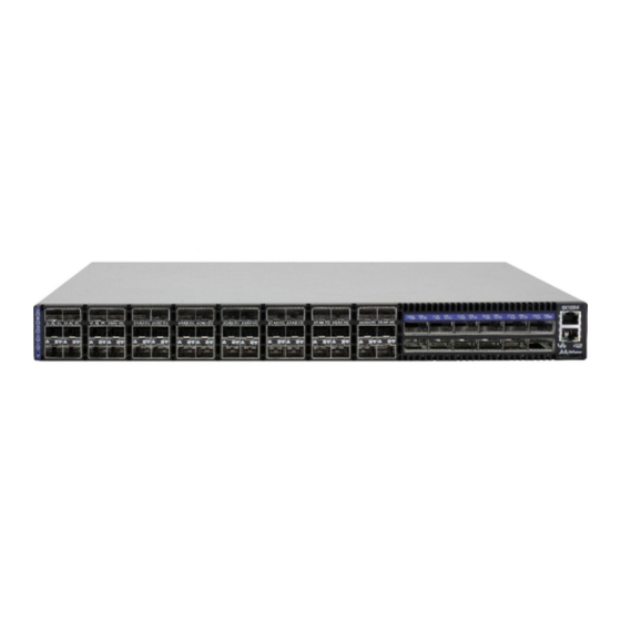
Ethernet Data-Centers. Figure 1: Connector Side View of the Switch Features • Based on Mellanox SwitchX-2 • Supports 48 SFP+ ports of 10 GbE • Supports 12 QSFP ports of 40 GbE Upgradable with a license to 56 GbE •... -
Page 12: Figure 2: Pull Out Tab
Rev 1.1 Overview Figure 2: Pull Out Tab SX1024 mgmt0 Mellanox S/N: MT1244X03494 P/N: MSX1024B‐1BFS Rev:A1 MAC: 0002C9020040 Pull out tab Mellanox Technologies... -
Page 13: Chapter 2 Ethernet Ports
Each of the 12 QSFP ports is capable of up to 40GbE, upgradable to 56 GbE with a license, as well as 10GbE with a QSA QSFP to SFP+ adapter or QSFP to SFP+ Mellanox cables. Each of the 48 SFP+ ports is capable of up to 10GbE. Mellanox Technologies... -
Page 14: Chapter 3 Basic Operation
Figure 4: System Status Indicators Green – OK Yellow – a fault in the system Led Color shows the switch status Red – Major Fault or Fatal Error Connector side Power side status LED status LED Mellanox Technologies... -
Page 15: Table 3: System Status Led Assignments
Major Error – Possible damage can result to the switch. Turn off immediately. e.g. bad firmware, can’t boot, overheated. If the system is booting up, it can take up to 5 minutes for the status led to change to green. Off – The system has no power. Mellanox Technologies... -
Page 16: Fan Status Indicators
Error – One or more fans is not operating properly. The system should be powered down and troubleshoot the fan module. Off – The fan unit is not receiving any power. Check that the fan unit is properly and completely inserted. Mellanox Technologies... -
Page 17: Power Supply Status Indicators
Fan status LEDs PS unit 1 status LED Mellanox Primary Power Supply Unit Fan Units Each PS unit has a single 2 color LED on the right side of the PS unit, that indicates the internal status of the unit. Mellanox Technologies... -
Page 18: Figure 9: Ps Unit Status Leds
This is a one color LED Flashing Orange — received symbol error The Bad Port indicator is located on the left side of the connector side panel of the unit. Table 6 shows the fan status LED assignment. Mellanox Technologies... -
Page 19: Figure 11: Port Led To Port Location Assignment
3.2.3.3 Port Connector LED Indicators The SFP+ ports come three rows to a column. The LEDs refer to the ports according to the color coding in Figure 11. Figure 11: Port LED to Port Location Assignment 43 44 45 47 48 Mellanox Technologies... -
Page 20: Air Flow
All components need to have the same air flow. A mismatch in the air flow will affect the heat dissipation. All PS units must have the same air flow as the fan modules. Figure 13 shows a mismatch in component airflow. Mellanox Technologies... -
Page 21: Figure 13: Component Airflow Mismatch (Wrong)
Rev 1.1 Figure 13: Component Airflow Mismatch (Wrong) All air flow labels must be the same. Any mismatch of these labels will affect the switch temperature. Table 8 shows the icons that indicate airflow using arrows and colors. Mellanox Technologies... -
Page 22: Sfp+ Cable Power Budget Classification
All SwitchX®-2 SX10XX SFP+ switches are designed for active cables with a maximum power per module of 1.5W. Typical power per port is 1W. Interfaces 3.5.1 Port Connector Interfaces There are 48 SFP+ ports and 12 QSFP ports. They are arranged according to the figure below. Mellanox Technologies... -
Page 23: Port Speed Configuration
This interface can be used to update software or firmware. • 1 connector that is labeled Use this connector to connect to the host PC. • 1 reset button • 1 I2C banana connector on the power supply side for FAE use only Mellanox Technologies... - Page 24 This connector can be used to install firmware upgrades, should Debug and Troubleshooting only. the firmware image be damaged and cannot be upgraded through a host PC or remotely. This interface is for support personnel and advanced users only. Mellanox Technologies...
-
Page 25: Reset Button
A quick push of this button performs this reset. When the button is held down for 15 sec- onds the switch is reset and the password is deleted. You will then be able to enter without a pass- word and make a new password for the user “admin”. Mellanox Technologies... -
Page 26: Chapter 4 Installation
6. During Lightning - Electrical Hazard During periods of lightning activity, do not work on the equipment or connect or dis- connect cables. Mellanox Technologies... - Page 27 Caution – Use of controls or adjustment or performance of procedures other than those specified herein may result in hazardous radiation exposure. CLASS 1 LASER PRODUCT and reference to the most recent laser standards: IEC 60 825-1:1993 + A1:1997 + A2:2001 and EN 60825-1:1994+A1:1996+ A2:2001 Mellanox Technologies...
- Page 28 The rack mounting holes conform to the EIA-310 standard for 19-inch racks. Take pre- cautions to guarantee proper ventilation in order to maintain good airflow at ambient temperature. Cable routing in particular should not impede the air exhaust from the chassis. Mellanox Technologies...
-
Page 29: Installation Kits
Parts included in the rail kit: • 2 rails • 16 recessed flat head screws You will have extras! • 2 rail slides • 10 caged nuts • 2 switch slides • 10 pan head screws M6 Mellanox Technologies... -
Page 30: Figure 18: Rack Rail Kit Parts
2. Choose which side of the switch you want even with the rack vertical support. Either the side with the power supply units or the side with the QSFP connectors can be even with one of the vertical rack supports. Mellanox Technologies... -
Page 31: Figure 19: Placement Of Switch In Rack
See Figure 20,“Mounting Options”. • Will the connector side be recessed past other equipment in the rack and will this be problematic? • The installation kit allows for a 2” (5cm) recess of the switch past the vertical support. Mellanox Technologies... -
Page 32: Figure 20: Mounting Options
7 screws per side are needed for the standard switch. 7 screws per side are needed for the standard switch. There are 16 screws in the kit; you will have left over screws. There are 16 screws in the kit; you will have left over screws. Mellanox Technologies... -
Page 33: Figure 22: Inserting The Caged Nuts
Figure 23: Slide the Rail into the Rail Slide This side of the rail kit goes on the side of the rack you will slide the switch into. This is the same side of the switch that will be next to the vertical support. Mellanox Technologies... -
Page 34: Grounding The Switch
Power Connections and Initial Power On The switch platform ships witone or twoh power supply units. For switches with only one unit installed, a second PS unit may be installed at a later time. Each supply has a separate AC recep- Mellanox Technologies... -
Page 35: Battery Replacement
Battery Replacement Mellanox Technologies does not support battery replacement. Customer removal of the switch cover will void the warrantee. Only Remove the cover to comply with WEEE directives or to dis- assemble for environmentally approved disposal. -
Page 36: Configuring The Switch The First Time
Figure 26: Console Port SX1024 Connect the host PC to this Mellanox Make sure to connect to the Console RJ-45 port of the switch and not to the (Ethernet) MGT port. No remote IP connection is available at this stage. Mellanox Technologies... -
Page 37: Table 10: Serial Terminal Program Configuration
Step 3: Enable IPv6? [yes] yes The management interface will be able to use IPv6 addresses. Step 4: Enable IPv6 autoconfig (SLAAC) on This turns on autoconfiguration of the IPv6 addresses. This is mgmt0 interface? [no] no unsuitable for DHCPv6. Mellanox Technologies... - Page 38 Config mode. return to. Otherwise hit <enter> to save changes and exit. Choice: <Enter> Configuration changes saved. To return to the wizard from the CLI, enter the “configuration jump-start” command from con- figuration mode. Launching CLI... <switch name> Mellanox Technologies...
-
Page 39: Table 12: Configuration Wizard Session - Ip Zeroconf Configuration
To change an answer, enter the step number to return to. Otherwise hit <enter> to save changes and exit. Choice: Configuration changes saved. To return to the wizard from the CLI, enter the "configuration jump-start" command from configure mode. Launching CLI... <switch name> [standalone: master] > Mellanox Technologies... -
Page 40: Table 13: Configuration Wizard Session - Static Ip Configuration
<switch name>[standalone: master] > 5. Before attempting a remote (for example, SSH) connection to the switch, check the mgmt0 interface configuration. Specifically, verify the existence of an IP address. To check the cur- rent mgmt0 configuration, enter the following commands: Mellanox Technologies... - Page 41 1. Set up an Ethernet connection between the switch and a local network machine using a stan- dard RJ-45 connector. 2. Start a remote secured shell (SSH) to the switch using the command “ssh -l <username> <switch ip address>.” rem_mach1 > ssh -l <username> <ip address> Mellanox Technologies...
-
Page 42: Rerunning The Wizard
<switch_IP_address> is the IP address of the switch. rem_mach1 > ssh -l <username> <switch ip address> Mellanox MLNX-OS® Switch Management Password: Last login: March 13, 2013 from 192.168.10.1 Mellanox Switch sx-43 [standalone: master] > 4. You can enter any supported command now. Mellanox Technologies... -
Page 43: Chapter 5 Extracting And Inserting Frus
Figure 28: Power Supply Unit Extraction Push Here Latch release If you are not immediately installing a new PSU you must install a blank so that the air flow for cooling the switch is not compromised. Mellanox Technologies... -
Page 44: Extracting And Inserting The Fan Units
Each fan module has two integral fans. This unit is intended for installation in a Restricted Access Location. A restricted access area can be accessed only through the use of a special tool, lock and key, or other means of security. Mellanox Technologies... -
Page 45: Figure 30: Air Flow Labels
1. Grasping the handle with your right hand, push the latch release with your thumb while pull- ing the handle outward. As the fan unit unseats, the fan unit status indicators will turn off. 2. Remove the fan unit. Mellanox Technologies... -
Page 46: Figure 31: Fan Module Latches
The green fan status indicator should light. If not, extract the fan unit and reinsert it. After two unsuccessful attempts to install the fan unit, power off the switch before attempting any system debug. Mellanox Technologies... -
Page 47: Chapter 6 Cabling
(unmapped). When using this feature you MUST go into the MLNX-OS® chassis management system and reconfigure the individual ports to split -4. See the MLNX-OS® Software Command Reference Guide for instructions on port configuration. Mellanox Technologies... -
Page 48: Cable Installation
Care should be taken not to impede the air flow through the ventilation holes next to the connec- tor ports. Cable lengths should be used which allow for routing horizontally around to the side of the chassis before bending upward or downward in the rack. Mellanox Technologies... -
Page 49: Chapter 7 Switch Shut Down Procedure
Switch Shut Down Procedure To shut down the switch run the command: Reload halt [noconfirm] The switch cannot be restarted remotely! To restart the switch you must physically go to the switch and unplug and plug in the power cord. Mellanox Technologies... -
Page 50: Chapter 8 Disassembly Of The Switch From The Rack
A quick push of this button performs this reset. When the button is held down for 15 sec- Mellanox Technologies... -
Page 51: Upgrading Software
Use the CLI in order to perform software upgrades. For further information please refer to the the MLNX-OS Software User Manual section Upgrading MLNX-OS® Software. Be sure to read and follow all of the instructions regarding the updating of the software on your switch system. Mellanox Technologies... -
Page 52: Chapter 9 Troubleshooting
When running IB check that the Subnet Manager has been started. The switch is off: Issue 7. Unplug the switch. Wait 5 minutes. Plug in the switch. If the switch does not come on, check the power supplies. Mellanox Technologies... - Page 53 Bus Dev VenId DevId Class Int PCIE0: link is not up. PCIE1: successfully set as root-complex 01 00 15b3 bd34 0c06 00 Net: ppc_4xx_eth0, ppc_4xx_eth1 Hit Ctrl+B to stop autoboot: 0 Mellanox MLNX-OS Boot Menu: 1. SX_PPC_M460EX 3.2.0000-dev-HA 2013-04-10 12:02:49 ppc Mellanox Technologies...
- Page 54 Rev 1.1 Troubleshooting 2. SX_PPC_M460EX 3.2.0000-dev-HA 2013-04-11 14:05:39 ppc 3. U-Boot prompt Choice: Select the image to boot. Mellanox Technologies...
-
Page 55: Appendix A Specification
Cable power / MAX 2.0 W Operating 0° to 45° Celsius Temperature TYP: 1.5 W Non-operating -40° to 70° Celsius Shock and Humidity: Shock and Vibration: ETSI EN 300 019-2-2: 1999-09 Operating 5% - 95% non-condensing Vibration/ Humidity Mellanox Technologies... -
Page 56: Approved Cables
For a list of all approved cables see: http://www.mellanox.com/related-docs/user_manuals/Mellanox_approved_cables.pdf EMC Certifications The list of approved certifications per switch in different regions of the world is located on the Mellanox Website at: http://www.mellanox.com/related-docs/user_manuals/Regulatory_and_Compliance_Guide.pdf EMC statements are also in the Regulatory and Compliance Guide. Mellanox Technologies... -
Page 57: China Ccc Warning Statement
SwitchX®-2 60 Port Ethernet Switch System Hardware User Manual Rev 1.1 China CCC Warning Statement Mellanox Technologies... -
Page 58: Appendix B Sfp+ Removal Tool Instructions
Rev 1.1 Appendix B: SFP+ Removal Tool Instructions Mellanox Technologies... -
Page 59: Appendix C Qsfp Interface
+3.3 V Power supply transmitter Vcc 1 +3.3 V Power Supply LPMode Low Power Mode Ground Tx3p Transmitter Non-Inverted Data Input Tx3n Transmitter Inverted Data Input Ground Tx1p Transmitter Non-Inverted Data Input Tx1n Transmitter Inverted Data Input Ground Mellanox Technologies... -
Page 60: Figure 35: Qsfp Connector Male And Female Views
Rev 1.1 Figure 35: QSFP Connector Male and Female Views 18.35 View into Rear of Connector 8.50 18.35 View into Front of Cage 8.50 Mellanox Technologies... -
Page 61: Appendix D Sfp+ Interface
SwitchX®-2 60 Port Ethernet Switch System Hardware User Manual Rev 1.1 Appendix D: SFP+ Interface 56.50 13.90 Mellanox Technologies 11.85 13.60 14.80 13.70 MTSFPP-SR Module 1.55 0.50 8.50 0.60 2.55 1.80 44.95 Figure 36: Rear View of Module With Pin Placement 13.70... - Page 62 MOD_ABS pulls line low to indicate module is plugged in. e. LOS is open collector output. Should be pulled up with 4.7kΩ – 10kΩ on host board to a voltage between 2.0V and 3.6V. Logic 0 indicates normal operation; logic 1 indicates loss of signal. Mellanox Technologies...
-
Page 63: Appendix E Rj-45 Console And I2C Interface
Looking into the Socket Bl/W RXD- RJ-45_RXD Br/W Table 16 - RJ-45 I2C Pinout Connection Signal Pin# Color TXD+ RJ-45_SDA TXD- RXD+ TXD+ Pin 1 TXD- RJ45_SDA Bl/W RXD+ RXD- RJ-45_SCL RXD- RJ45_SCL Br/W Pin 8 Looking into the Socket Mellanox Technologies... -
Page 64: Appendix F Accessory And Replacement Parts
300W Power Supply w/ Connector side to Power Supply side air flow MSX60-PR Power cord Type C13-C14 ACC000500 Installation Kit for short switches in racks 40-60 cm deep MSX60-BKIT Installation Kit for short or standard switches in racks 60-80 cm deep MSX60-SKIT Mellanox Technologies... -
Page 65: Appendix G Avertissements De Sécurité D'installation (French)
Les câbles InfiniBand en cuivre sont lourds et ne sont pas flexibles, il faut donc faire très attention en les branchant et en les débranchant des connecteurs. Consultez le fab- ricant des câbles pour connaître les mises en garde et les instructions spéciales. Mellanox Technologies... - Page 66 Avant de brancher l’appareil à la conduite d’alimentation, les vis de protection à la terre du terminal de l’appareil doivent être appliquées à l’installation de protection à la Terre du bâtiment. 14. Installation du matériel Ce matériel ne doit être installé, remplacé ou entretenu que par du personnel formé et qualifié. Mellanox Technologies...
- Page 67 CEI 60 825-1:1993 + A1:1997 + A2:2001 et NE 60825-1:1994+A1:1996+ A2:2001 20. S’assurer que les enceintes sont appropriées Des enceintes électriques, mécaniques et incendie adaptées doivent être fournies par le fabricant du produit final ou par l’utilisateur final. Mellanox Technologies...
- Page 68 Conformément à la Directive WEEE 2002/96/EC, les déchets d'équipements élec- triques et électroniques (EEE) doivent être triés et ne peuvent être éliminés avec les déchets ménagers. Veuillez disposer de ce produit et de tous ses composants de manière responsable et respectueuse de l’environnement. Mellanox Technologies...
-
Page 69: Appendix H Installation - Sicherheitshinweise (German)
Um alle Einhieten spannungsfrei zu machen sind die Netzstecker aller Netz- teile zu entfernen Risk of electric shock and energy hazard. The PSUs are all independent. Disconnect all power supplies to ensure a powered down state inside of the switch platform. Mellanox Technologies... - Page 70 Für die europäischen Zusammenhang, wählen Sie ein Netzkabel, das international harmonisiert und der Aufschrift "<HAR>", 3 - Leiter, mindestens 0,75 mm2 Draht, bewertet mit 300 V, mit einem PVC-Mantel isoliert. Das Kabel muss eine angespritztem Stecker bewertet bei 250 V, 10 A. " Mellanox Technologies...
- Page 71 20. Bodily Injury Due to Weight Use enough people to safely lift this product. <40 lbs 70 - 121 lbs >121 lbs 40 - 70 lbs <18 kgs 32 - 55 kgs >55 kgs 18 - 32 kgs Mellanox Technologies...
-
Page 72: Appendix I Advertencias De Seguridad Para La Instalación (Spanish)
6. Dos fusibles, uno en el polo y otro en el neutro Dos fusibles, uno en el polo y otro en el neutro. Quitar los cables de corriente antes de abrir la tapa de este producto o tocar cualquier componente interno. Mellanox Technologies... - Page 73 12. Eliminación de equipos La eliminación definitiva de este equipo se debe efectuar conforme a todas las leyes y reglamentaciones nacionales. 13. Códigos eléctricos locales y nacionales Este equipo se debe instalar conforme a los códigos eléctricos locales y nacio- nales. Mellanox Technologies...
- Page 74 (EEE) se deben recolectar por separado y no se deben eliminar junto con residuos domésticos. Al deshacerse de este producto y de todas sus partes, hágalo de una manera respon- sable y respetuosa con el medio ambiente. Mellanox Technologies...
Need help?
Do you have a question about the SwitchX-2 and is the answer not in the manual?
Questions and answers