Sign In
Upload
Manuals
Brands
Mellanox Technologies Manuals
Network Router
SwitchX-2 SX1012
Mellanox Technologies SwitchX-2 SX1012 Manuals
Manuals and User Guides for Mellanox Technologies SwitchX-2 SX1012. We have
2
Mellanox Technologies SwitchX-2 SX1012 manuals available for free PDF download: User Manual
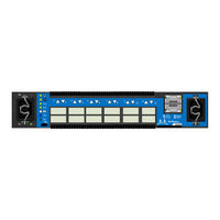
Mellanox Technologies SwitchX-2 SX1012 User Manual (86 pages)
SwitchX-2 12 Port Ethernet Switch System
Brand:
Mellanox Technologies
| Category:
Switch
| Size: 1.75 MB
Table of Contents
Table of Contents
3
List of Figures
5
List of Tables
6
Revision History
7
Table 1: Revision History Table
7
About this Manual
8
Intended Audience
8
Related Documentation
8
Conventions
8
Table 2: Reference Documents and Web Sites
8
Mellanox Part Numbering Legend
9
Chapter 1 Overview
10
Features
10
Figure 1: 12 Port Ethernet Switch
10
Figure 2: Connector Side View of the Switch
10
Table 3: General System Features
11
Table 4: Management Software
11
Table 5: Ethernet Features
12
Serial Number and Product Version Information
13
Ethernet Ports
13
Figure 3: Pull out Tab
13
Chapter 2 Basic Operation
14
Switch Platform Hardware Overview
14
Status Leds
14
Figure 4: Switch System Connector Side Panels
14
Figure 5: System Status LEDS
14
Table 6: System Status Leds
15
Figure 6: Switch Status LED
16
Table 7: Switch Status LED Assignments
16
Figure 7: Fan Status LED Connector Side
17
Table 8: Fan Status LED Assignments
17
Figure 8: Power Status LED Connector Side
18
Table 9: PS Unit Status LED Assignments
18
Figure 9: Bad Port LED
19
Table 10: Bad Port LED Assignments
19
Port Connector Leds
20
Figure 10: Identifier LED
20
Figure 11: Port Leds
20
Table 11: Port Connector Physical and Logical Link Assignments for Ethernet Mode
20
Air Flow
21
QSFP Cable Power Budget Classification
21
Interfaces
21
Figure 12: Management Interfaces
21
Figure 13: Rear of Switch
22
Figure 14: Reset Button
23
Figure 15: Port Numbering
23
Figure 16: Top and Bottom QSFP Port Orientation
24
Chapter 3 Installation
25
Installation Safety Warnings
25
Equipment Installation
26
Package Contents
29
Mechanical Installation
30
Figure 17: Placing the Bumpers
30
Figure 18: Installation Kit Parts for a Side by Side Installation
31
Figure 19: Screw on the Switch Mounted Rails
32
Figure 20: Two Switch Frame
33
Figure 21: Placement of Frame in the Rack
33
Figure 22: Placing the Spacer in the Rack
34
Figure 23: Using the Spacer Bushings
34
Figure 24: Insert Switch into Frame
35
Grounding the Switch
36
Power Connections and Initial Power on
36
Figure 25: Status Leds 5 Minutes after Power on
36
Configuration
37
Figure 26: Two Power Inlets - Electric Caution Notifications
37
Figure 27: Console Port
38
Table 12: Serial Terminal Program Configuration
38
Table 13: Configuration Wizard Session - DHCP Configuration (Example)
39
Table 14: Configuration Wizard Session - Static IP Configuration
40
Table 15: Configuration Wizard Session - Zeroconf Configuration
41
Starting a Remote Connection to the Switch
42
Chapter 4 Cabling
44
Cable Installation
44
Splitting the Data Stream Using Breakout (Fanout) Cables
44
Figure 28: Top and Bottom QSFP Cable Orientation
44
Figure 29: Breakout or Fanout Cable
45
Chapter 5 Switch Management
46
Upgrading Software
46
Chapter 6 Troubleshooting
47
Appendix A Specification
49
Table 16: SX1012 Specification Data
49
Approved Cables
50
EMC Certifications
50
A.1 Approved Cables
50
A.2 EMC Certifications
50
China CCC Warning Statement
51
Appendix B Thermal Threshold Definitions
52
Appendix C QSFP Interface
53
Figure 30: QSFP Connector Male and Female Views
54
Appendix D RJ-45 CONSOLE and I2C Interface
55
Table 17: RJ-45 CONSOLE Pinout
55
Table 18: RJ-45 I2C Pinout
55
Appendix E Accessory and Replacement Parts
56
Table 19: Opns for Replacement Parts
56
Appendix F Disassembly of the Switch from the Rack
57
F.1 Disposal
57
Appendix G Avertissements de Sécurité Pour L'installation (French)
58
Appendix H Installation - Sicherheitshinweise(German)
63
Appendix I Advertencias de Seguridad de Instalación(Spanish)
67
Appendix J Предупреждения По Технике Безопасности При Установке(Russian)
72
Appendix K Avertismente Privind Siguranţa la Instalare (Romanian)
77
Appendix L 安裝安全性警告 (Chinese)
82
Advertisement
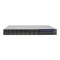
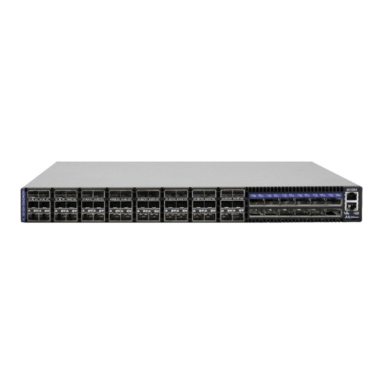
Mellanox Technologies SwitchX-2 SX1012 User Manual (74 pages)
60 Port Ethernet Switch System
Brand:
Mellanox Technologies
| Category:
Network Router
| Size: 1.2 MB
Table of Contents
Table of Contents
3
List of Figures
5
List of Tables
7
Revision History
8
Table 1: Revision History Table
8
About this Manual
9
Table 2: Reference Documents and Web Sites
9
Mellanox Part Numbering Legend
10
Chapter 1 Overview
11
Features
11
Serial Number and Product Version Information
11
Figure 1: Connector Side View of the Switch
11
Figure 2: Pull out Tab
12
Chapter 2 Ethernet Ports
13
Chapter 3 Basic Operation
14
Switch Platform Hardware Overview
14
Status Leds
14
System Status Indicators
14
Figure 3: QSFP Switch System Power and Connector Side Panels
14
Figure 4: System Status Indicators
14
Table 3: System Status LED Assignments
15
Fan Status Indicators
16
Figure 5: Fan Status LED Connector Side
16
Figure 6: Fan Status LED Power Side
16
Table 4: Fan Status LED Assignments
16
Power Supply Status Indicators
17
Figure 7: Power Status LED Connector Side
17
Figure 8: Power Side Panel
17
Figure 9: PS Unit Status Leds
18
Figure 10: Bad Port LED
18
Table 5: PS Unit Status LED Assignments
18
Figure 11: Port LED to Port Location Assignment
19
Table 6: Bad Port LED Assignments
19
Air Flow
20
Figure 12: Port Leds
20
Table 7: Port Connector Physical and Logical Link Assignments for Ethernet
20
Figure 13: Component Airflow Mismatch (Wrong)
21
SFP+ Cable Power Budget Classification
22
Interfaces
22
Port Connector Interfaces
22
Table 8: Air Flow Direction
22
Port Speed Configuration
23
Management and Firmware Updating Interfaces
23
Figure 14: Port Numbering
23
Figure 15: Top and Bottom QSFP Port Orientation
23
Figure 16: Top and Bottom SFP+ Port Orientation
23
Reset Button
25
Figure 17: Reset Button
25
Chapter 4 Installation
26
Installation Safety Warnings
26
Installation Kits
29
Package Contents
29
Mechanical Installation
29
Table 9: Installation Kit According to Rack Size
29
Figure 18: Rack Rail Kit Parts
30
Figure 19: Placement of Switch in Rack
31
Figure 20: Mounting Options
32
Figure 21: Screwing on the Rail
32
Figure 22: Inserting the Caged Nuts
33
Figure 23: Slide the Rail into the Rail Slide
33
Grounding the Switch
34
Power Connections and Initial Power on
34
Figure 24: Status Leds 5 Minutes after Power on
34
Battery Replacement
35
Figure 25: Two Power Inlets - Electric Caution Notifications
35
Configuring the Switch the First Time
36
Managed (Internally Managed) Switches
36
Figure 26: Console Port
36
Table 10: Serial Terminal Program Configuration
37
Table 11: Configuration Wizard Session - IP Configuration by DHCP
37
Table 12: Configuration Wizard Session - IP Zeroconf Configuration
39
Table 13: Configuration Wizard Session - Static IP Configuration
40
Rerunning the Wizard
42
Connecting to the Switch Platform
42
4.11.1 Starting a Remote Connection to the Switch
42
Starting an SSH Connection to the Switch (CLI)
42
Chapter 5 Extracting and Inserting Frus
43
Extracting and Inserting the Power Supply Unit
43
Figure 27: Fan and PS Unit Air Flow Direction
43
Figure 28: Power Supply Unit Extraction
43
Extracting and Inserting the Fan Units
44
Figure 29: PS Unit Pulled out
44
Figure 30: Air Flow Labels
45
Figure 31: Fan Module Latches
46
Chapter 6 Cabling
47
Splitting the Data Stream Using Breakout (Fanout) Cables
47
Figure 32: Breakout or Fanout Cable
47
Figure 33: Port Splitting Options
47
Cable Installation
48
Figure 34: SFP+ Cable Orientation
48
Chapter 7 Switch Shut down Procedure
49
Chapter 8 Disassembly of the Switch from the Rack
50
Disposal
50
Upgrading Software
51
Chapter 9 Troubleshooting
52
Appendix A Specification
55
Table 14: SX1024 Specification Data
55
A.1 Approved Cables
56
A.2 EMC Certifications
56
Approved Cables
56
EMC Certifications
56
China CCC Warning Statement
57
Appendix B SFP+ Removal Tool Instructions
58
Appendix C QSFP Interface
59
Figure 35: QSFP Connector Male and Female Views
60
Appendix D SFP+ Interface
61
Appendix E RJ-45 CONSOLE and I2C Interface
63
Table 15: RJ-45 CONSOLE Pinout
63
Table 16: RJ-45 I2C Pinout
63
Appendix F Accessory and Replacement Parts
64
Table 17: Opns for Replacement Parts
64
Appendix G Avertissements de Sécurité D'installation (French)
65
Appendix H Installation - Sicherheitshinweise (German)
69
Appendix I Advertencias de Seguridad para la Instalación (Spanish)
72
Advertisement
Related Products
Mellanox Technologies SwitchX-2 MSX1024B-1BRS
Mellanox Technologies SwitchX-2 MSX1024B-1BFS
Mellanox Technologies SwitchX-2 MSX1024B-2BFS
Mellanox Technologies SwitchX-2 MSX1024B-2BRS
Mellanox Technologies SX1018HP
Mellanox SX1016
Mellanox SX1410
Mellanox SX1710
Mellanox Technologies SwitchX-2 MSX1012B-2BFS
Mellanox Technologies SwitchX-2 MSX1012B-1BFS
Mellanox Technologies Categories
Switch
Computer Hardware
Adapter
Network Card
Network Router
More Mellanox Technologies Manuals
Login
Sign In
OR
Sign in with Facebook
Sign in with Google
Upload manual
Upload from disk
Upload from URL