Table of Contents
Advertisement
Advertisement
Table of Contents

Subscribe to Our Youtube Channel
Related Manuals for Advantech PCI-COMM Series


Summary of Contents for Advantech PCI-COMM Series
- Page 1 PCI-COMM Series Industrial Serial Communication Cards User Manual...
- Page 2 Acknowledgements Award is a trademark of Award Software International, Inc. VIA is a trademark of VIA Technologies, Inc. IBM, PC/AT, PS/2 and VGA are trademarks of International Business Machines Corporation. Intel and Pentium are trademarks of Intel Corporation.
- Page 3 Product Warranty (2 years) Advantech warrants to you, the original purchaser, that each of its prod- ucts will be free from defects in materials and workmanship for two years from the date of purchase. This warranty does not apply to any products which have been repaired or altered by persons other than repair personnel authorized by Advantech, or which have been subject to misuse, abuse, accident or improper instal- lation.
- Page 4 This product has passed the CE test for environmental specifications when shielded cables are used for external wiring. We recommend the use of shielded cables. This kind of cable is available from Advantech. Please contact your local supplier for ordering information. FCC Class A This equipment has been tested and found to comply with the limits for a Class A digital device, pursuant to Part 15 of the FCC Rules.
- Page 5 Technical Support and Assistance Step 1. Visit the Advantech web site at www.advantech.com/support where you can find the latest information about the product. Step 2. Contact your distributor, sales representative, or Advantech's cus- tomer service center for technical support if you need additional assistance.
- Page 6 PCI-COMMUNICATION User Manual...
-
Page 7: Table Of Contents
Contents Chapter 1 Introduction ............. 2 Description ................ 2 Features ................3 Specifications ..............3 Ordering Information ............5 1.4.1 Accessories ..............7 Table 1.1:PCI Communication Cards Selection Guide . 8 Chapter 2 Hardware Configuration ......10 Initial Inspection.............. 10 Jumper and Switch Locations ......... - Page 8 Figure 2.26:Passive Mode Jumper Setting ....33 Figure 2.27:Resistor Selection ........34 Card Installation .............. 35 Chapter 3 Driver Setup & Installation......38 Introduction ..............38 Driver Setup ..............38 3.2.1 Steps for Windows 98/2000/XP Driver Setup ..... 38 Reboot System after Win98/2000/XP Driver Setup ..44 3.3.1 PCI UARTs Device Driver Installation .......
- Page 9 Pin assignments ............... 74 5.1.1 PCI-1601A/AU/B/BU, PCI-1602A/AU/B/BU .... 74 Table 5.1:PCI-1601/1602 Male DB9 on bracket ..74 Figure 5.1:PCI-1601/1602 Pin Assignment ....74 5.1.2 PCI-1602UP ..............75 Table 5.2:PCI-1602UP Male DB9 on cable ....75 Table 5.3:PCI-1602UP Female DB25 on bracket ..75 5.1.3 PCI-1603 ..............
- Page 10 Table 5.28:Terminal or PC (DTE) Connections ..92 Table 5.29:Modem Connections ........93 Table 5.30:Terminal without Handshake ..... 93 5.2.2 RS-422 Signal Wiring ..........94 Table 5.31:RS-422 DB9 Pin Assignment ....94 5.2.3 RS-485 Signal Wiring ..........95 Figure 5.2:RS-485 Wiring Topology ......95 PCI-COMMUNICATION User Manual...
- Page 11 Introduction This chapter provides detailed specifi- cations for the PCI COMMUNICA- TION cards. Sections include: • Description • Features • Specifications • Ordering Information • Selection Guide...
-
Page 12: Chapter 1 Introduction
Chapter 1 Introduction 1.1 Description The PCI Local Bus is a high-performance bus that provides a processor- independent data path between the CPU and high-speed peripherals. PCI is a robust inter-connect mechanism designed specifically to accommo- date multiple high performance peripherals for series communication, SCSI, LAN, etc. -
Page 13: Features
1.2 Features • PCI Specification 2.1/2.2 compliant • Speeds up to 921.6 kbps • 16PCI952/954 , 16C954 UARTs with 128-byte FIFOs standard • I/O address automatically assigned by PCI plug-and play • OS supported: Windows 98/ME/2000/XP, Linux • Optional surge protection •... - Page 14 • Speed (bps) : PCI-1603: RS-232: 50~203.4k Current Loop: 50~57.6k Others: 50 ~ 921.6 k • Data Signals: TxD, RxD, RTS, CTS, DTR, DSR, DCD, GND (for RS-232) RI (for PCI-1603, PCI-1604UP, PCI-1610A/AJU/B/CU/AUP/UP) TxD, RxD, RTS, CTS (for RS-422/485) Tx+, Tx-, Rx+, Rx- (for PCI-1603 Current loop) Data+, Data-, GND (for PCI-1602UP RS-485) TxD, RxD, Rx+, Rx-, RTS+, RTS-, CTS+, CTS-, GND (for PCI- 1602UP RS-422)
-
Page 15: Ordering Information
• Operating Temperature: 0~ 65° C (See IEC 68-2-1, 2), (32~149° F) • Operating Humidity: 5 ~ 95% Relative Humidity, non-condensing (See IEC 68-2-3) • Storage Temperature: -25 ~ 85° C (-13~185° F) • Current-loop Interface Signal Driver/receiver: 6N136 Signals: TxD+, TxD-, RxD+, RxD- •... - Page 16 • PCI-1610AJU: 4-port RS-232 Universal PCI Comm. Card w/ RJ45 connector • PCI-1610AUP: 4-port RS-232 Low-Profile Universal PCI Comm. Card • PCI-1610B: 4-port RS-232 PCI Comm. Card, w/surge protection • PCI-1610CU: 4-port RS-232 Universal PCI Comm. Card, w/isolation and surge protection •...
-
Page 17: Accessories
1.4.1 Accessories • OPT8AP: 8-Port RS-232 Connection Box/Female DB25 Connectors (DCE) (1 m cable connectors with card and connection box included) • OPT8ASP: 8-Port RS-232 Connection Box/Female DB25 Connec- torsw/ surge protection (DCE) (1m cable connectors with card and connection box included) •... -
Page 18: Table 1.1:Pci Communication Cards Selection Guide
Table 1.1: PCI Communication Cards Selection Guide Model Name Form Factor Ports Comm. Protection Interface Surge Isolation Support PCI-1601 RS-422/485 2500V Universal Universal 2500V PCI-1602 3000V 2500V 3000V Universal 3000V Universal 2500V 3000V Low-Profile/ 2500V 2500V Universal PCI-1603 Universal RS-232/Cur- 3000V rent loop PCI-1604UP... - Page 19 Hardware Configuration This chapter provides information on the hardware configuration of PCI COMMUNICATION cards. Sections include: • Initial Inspection • Jumper and Switch Locations • Jumper Settings • Card Installation...
-
Page 20: Chapter 2 Hardware Configuration
Chapter 2 Hardware Configuration 2.1 Initial Inspection You should find the following items inside the shipping package: PCI communication interface card Industrial Communication Driver, Utility and PCI communication card user manual in ICOM CD-ROM We carefully inspected the PCI communication card series mechanically and electrically before we shipped it. -
Page 21: Figure 2.1: Pci-1601A/B Silk Screen
2.2 Jumper and Switch Locations Figure 2.1: PCI-1601A/B Silk Screen Chapter 2... -
Page 22: Figure 2.2:Pci-1601Au/Bu Silk Screen
Figure 2.2: PCI-1601AU/BU Silk Screen PCI-COMMUNICATION User Manual 12... -
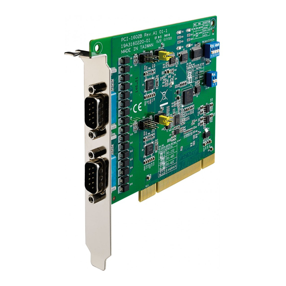
Page 23: Figure 2.3:Pci-1602A/B Silk Screen
Figure 2.3: PCI-1602A/B Silk Screen Chapter 2... -
Page 24: Figure 2.4:Pci-1602Au/Bu Silk Screen
Figure 2.4: PCI-1602AU/BU Silk Screen PCI-COMMUNICATION User Manual 14... -
Page 25: Figure 2.5:Pci-1602Up Silk Screen
Figure 2.5: PCI-1602UP Silk Screen Chapter 2... -
Page 26: Figure 2.6:Pci-1603 Silk Screen
Figure 2.6: PCI-1603 Silk Screen PCI-COMMUNICATION User Manual 16... -
Page 27: Figure 2.7:Pci-1604Up Silk Screen
Figure 2.7: PCI-1604UP Silk Screen Chapter 2... -
Page 28: Figure 2.8:Pci-1610A/B Silk Screen
Figure 2.8: PCI-1610A/B Silk Screen PCI-COMMUNICATION User Manual 18... -
Page 29: Figure 2.9:Pci-1610Cu Silk Screen
Figure 2.9: PCI-1610CU Silk Screen Chapter 2... -
Page 30: Figure 2.10:Pci-1610Aup/Up Silk Screen
Figure 2.10: PCI-1610AUP/UP Silk Screen PCI-COMMUNICATION User Manual 20... -
Page 31: Figure 2.11:Pci-1610Ajp Silk Screen
Figure 2.11: PCI-1610AJP Silk Screen Chapter 2... -
Page 32: Figure 2.12:Pci-1611U Silk Screen
Figure 2.12: PCI-1611U Silk Screen PCI-COMMUNICATION User Manual 22... -
Page 33: Figure 2.13:Pci-1612A/B Silk Screen
Figure 2.13: PCI-1612A/B Silk Screen Chapter 2... -
Page 34: Figure 2.14:Pci-1612Au/U Silk Screen
Figure 2.14: PCI-1612AU/U Silk Screen PCI-COMMUNICATION User Manual 24... -
Page 35: Figure 2.15:Pci-1612Cu Silk Screen
Figure 2.15: PCI-1612CU Silk Screen Chapter 2... -
Page 36: Figure 2.16:Pci-1620A/B Silk Screen
Figure 2.16: PCI-1620A/B Silk Screen PCI-COMMUNICATION User Manual 26... -
Page 37: Figure 2.17:Pci-1620Au/U Silk Screen
Figure 2.17: PCI-1620AU/U Silk Screen Chapter 2... -
Page 38: Figure 2.18:Pci-1622Cu Silk Screen
Figure 2.18: PCI-1622CU Silk Screen PCI-COMMUNICATION User Manual 28... -
Page 39: Jumper Settings
2.3 Jumper Settings This section tells how to set the jumpers to configure your card. It gives the card default configuration and your options for each jumper. 2.3.1 How to Set Jumpers You configure your card to match the needs of your application by setting jumpers. -
Page 40: Default Settings
2.3.2 Default Settings The board is shipped with default settings. If you need to change these settings, however, see the following sections. Otherwise, you can simply install the card. PCI-1601/1602/1611/1612/1622. Table 2.1: PCI-1601/1602/1611/1612/1622 Default Setting RS-422 RS-422/485 Mode Auto Enable Mode PCI-1603 The board will be shipped in the RS-232 mode, passive Rx and active Tx. -
Page 41: Mode Selection By Jumper/Dip Settings
2.3.3 Mode Selection by Jumper/DIP Settings RS-232/422/485 Selection (for PCI-1612A/B/AU/U/CU) Should you wish to configure the PCI-1612A/B/AU/U/CU to operate in the RS-232 mode, the bottom two pins of the 12*3 pin jumper should be connected. For RS-422/ RS-485 mode selection, the upper two pins of the 12*3 pin jumper should be connected as shown below. -
Page 42: Figure 2.23:Pci-1603 Rs-232 Mode Jumper Setting
PCI-1603 RS-232/Current-loop Mode Selection For RS-232 mode operations, the jumpers will be set as the default mode. The jumpers on the 10*2 pin jumper must be set to A, B, C, D and E. Figure 2.23: PCI-1603 RS-232 Mode Jumper Setting To enable the channel to operate in the current-loop mode, you should set F, G, H, I and J on the 10*2 pin jumpers. -
Page 43: Figure 2.26:Passive Mode Jumper Setting
C and D are set to be passive Rx, and F is set to be passive Tx. Figure 2.26: Passive Mode Jumper Setting You may configure both Tx and Rx on one port to operate in the same mode, or you can configure each Tx and Rx on one port to operate in dif- ferent modes. -
Page 44: Figure 2.27:Resistor Selection
Terminator resistor setup (for PCI-1601/1602/1611/1612/1622) You can install terminator resistors if necessary to match impedance. Each signal line (Tx, Rx) has a separate resistor. Especially in fields with serious electric noise, installing terminal resis- tors is helpful to stabilize communications. Make sure that both sides of the RS-485 communication ports are installed on BUS. -
Page 45: Card Installation
2.4 Card Installation Note: We strongly recommend that you install the soft- ware driver before you install the hardware into your system, since this will guarantee a smooth and trouble-free installation process. Turn off your PC’s power supply whenever you install or remove the PCI communication card or its cables. - Page 46 PCI-COMMUNICATION User Manual 36...
- Page 47 Driver Setup and Installation This chapter describes the driver instal- lation, configuration and removal pro- cedures for the Windows operating system, including Windows 98/2000/ Sections include: • Introduction • Driver Setup...
-
Page 48: Chapter 3 Driver Setup & Installation
Chapter 3 Driver Setup & Installation 3.1 Introduction This chapter describes the driver installation, configuration and removal procedures for the Windows operating system, including Windows 98/ NT/2000/XP. We strongly recommend that you install the software driver before you install the hardware into your system, since this will guarantee a smooth and trouble-free installation process. - Page 49 After the setup program is launched, you’ll see the following Screen. Click the Continue button and the catalogue select page appears. Then click the Installation button for installation Chapter 3...
- Page 50 Choose the driver you want to install, then click the hyperlink. Click Next to continue installation. PCI-COMMUNICATION User Manual 40...
- Page 51 Type user name and company name, then click Next. Just click Next to accept the default installation folder, or you can specify a folder by clicking the Browse button. Chapter 3...
- Page 52 Select a program folder or type a new folder name. Click Back to review or change your setting, or click Next to begin copying files. PCI-COMMUNICATION User Manual 42...
- Page 53 Perfom the requested operations and select Finish. Chapter 3...
-
Page 54: Reboot System After Win98/2000/Xp Driver Setup
3.3 Reboot System after Win98/2000/XP Driver Setup 3.3.1 PCI UARTs Device Driver Installation When you reboot your system, Windows 98/2000/XP will recog- nize your card devices and will automatically search for the device driver for PCI UARTs as shown in the following dialog box. Choose “Search for the best driver for your device”... - Page 55 You don’t have to choose the location of the device driver program, since it is already installed on your system. Just click Next to pro- ceed. Windows 98/2000/XP has found the driver location and is ready to install the driver. Click Next. Chapter 3...
-
Page 56: Pci Bridge Device Driver Installation
The driver installation is complete. Click Finish. 3.3.2 PCI Bridge Device Driver Installation After the PCI UARTs device driver has been installed, Windows 98/ 2000/XP will recognize the PCI Bridge device and automatically install the device driver for PCI Bridge. PCI-COMMUNICATION User Manual 46... -
Page 57: Verify Your Win98/2000/Xp Driver Setup
3.4 Verify your Win98/2000/XP Driver Setup After you have installed your card, go to Control Panel/System/Device Manager to look for the Device Name that will appear after you have installed the driver. Note: If your device has not been properly installed, there will be an exclamation mark (!) on the device name to indi- cate a conflicting device. - Page 58 You can also check the COM Port properties by double-clicking the spe- cific com port device configuration you want to see. On the Properties sheet, select the specific tabs to see relevant information. On the General tab, you can see whether the device is working properly. If your device functions normally, you can see a message under the Device status box, stating “This device is working properly”.
- Page 59 On the Settings tab, you can view relevant information about that specific port, as you can see on the figures below. Chapter 3...
-
Page 60: Configuring Serial Devices For Win 98/2000/Xp
If you want to configure FIFO Properties, select the FIFOs tab. On the tab, you can see the relevant FIFO configurations. We recommend you use the default settings. However, you can set the configurations manu- ally according to your preferences. If you want to restore the default set- tings, just click the Restore Default button. - Page 61 Select Device Manager tab on the System Properties sheet. Click the plus sign (+) on the right of the ADSPCIUART device category to expand it. As shown on the figure below, you can see Advantech PCI UARTs and Advantech PCI Bridge device names listed under the device category.
-
Page 62: Configuring A Pci Uarts Device
3.5.1 Configuring a PCI UARTs Device Double-click the Advantech PCI UARTs device to evoke its Prop- erties page, and then select the Resource tab on the Properties page to look up or configure the current settings of the PCI UARTs device. -
Page 63: Configuring A Pci Bridge Device
3.5.2 Configuring a PCI Bridge Device Double-click the Advantech PCI Bridge device to evoke its Properties page, and then select the Resources tab on the Properties page to look up or configure the current configuration of the PCI Bridge device to make sure there are no conflicting devices. -
Page 64: Remove Pci Icom Series Device
3.6 Remove PCI ICOM Series Device Access Control Panel/System to bring up the System Properties window. Select the Device Manager tab. PCI-COMMUNICATION User Manual 54... - Page 65 Click the plus sign (+) on the left of the Ports (COM & LPT) device category to expand it. Select the specific “Advantech PCI communication port” you want to remove, and click the Remove button to remove the device you had selected. The following dialog box will appear to prompt you again to make sure you really want to remove the device from your system.
- Page 66 Click the plus sign (+) on the left of the ADSPCIUART device cat- egory to expand it, and select the Advantech PCI UARTs or Advantech PCI Bridge you want to remove. Note: You must remove all used ports settings and device settings before you remove the device, or there may be a mistake in the port setting when you install another card.
-
Page 67: Driver Uninstall
Click the Remove button and the following dialog boxes appear to prompt you whether you really want to remove the device. Note: We recommend you to remove the original device before installing another model of Advantech PCI ICOM series device in the same PCI slot. 3.7 Driver Uninstall Insert the ICOM CD and click the driver you want to uninstall. - Page 68 Choose “Modify” radio button if you want to save another driver. Or choose “Remove” radio button to remove all installed compo- nents. Click “Finish“ button to complete the uninstall. PCI-COMMUNICATION User Manual 58...
- Page 69 ICOM Tools This chapter provides information on installation and usage of ICOM Tools. Sections include: • Introduction • Installation • User Interface of ICOM Tools...
-
Page 70: Chapter 4 Icom Tools
Chapter 4 ICOM Tools 4.1 Introduction Advantech ICOM Tools is a convenient utility that has been designed to help you test the performance of ICOM cards through analyzing the port status. It features an easy to use graphical user interface that will soon make you familiar with testing via menu commands and toolbar buttons. -
Page 71: User Interface Of Icom Tools
4.3 User Interface of ICOM Tools 4.3.1 Menu Bar On the Menu Bar you can select various menu commands to perform port-testing functions. You can also use the short-cut keys. Port Submenu Select: Select the ports you want to configure Setup: Setup the configuration of a specific port Close: Close a specific port Run: Run the test on a specific port... -
Page 72: Tool Bar
4.3.2 Tool Bar Using the Tool Bar buttons is a more intuitive way to implement the functions of ICOM Tools. Port Select: Selects the port(s) you want to perform test- ing on Port Setup: Sets up configuration of the port you have selected Port Close: Closes the port you have selected Port Run: Runs the port test on the port you have selected... -
Page 73: Com Port Tab
4.3.3 Com Port Tab Each Com Port tab represents a specific port you have selected for test and configuration. On the tab, you can see the Transfer Mode, Port Sta- tus, and Message Logo area. Transfer Modes You can specify the transfer mode to be Normal, loopback (active) or loopback (passive). -
Page 74: Port Status
4.3.4 Port Status DTR (data-terminal-ready) DSR (data-set-ready) RTS (request-to-send) CTS (clear-to-send) CD (carrier-detect) For RS-232 specifications, DTR and RTS are for output signals and can be toggled on and off by double-clicking the labels (such as DTR, DSR, RTS, CTS, CD) under the red/green marks. However, if you are using RTS/CTS for flow control to run the test, you will see the RTS mark appear in black. -
Page 75: Tx Slide Bar
4.3.6 Tx Slide Bar The Tx Slide Bar allows you to control the overall system loading. You can adjust the transmission rate of your port(s) from 0% to 100%. Just drag the slide button along the track to adjust the transmission rate. 4.3.7 Performance Listing Area On the performance listing area, you can see the relevant information, such as Rx Length (received packet byte length), Bytes/Sec (transmission... -
Page 76: Using The Icom Tools Utility
4.4 Using the ICOM Tools Utility To launch the ICOM Tools testing utility, access Start/Programs/Advan- tech PCI Comm Tools/COM Examine Tools to start the port testing util- ity. 4.4.1 Port Selection Please follow the steps below to make your port selection: Launch ICOM Tools. -
Page 77: Figure 4.2:Select Port Dialog Box
Select the port(s) you want to test by the Port/Select menu com- mand or by clicking the Port Select button on the Toolbar, and a dialog box such as Fig. 2 will appear. Figure 4.2: Select Port dialog box Select the port(s) you want to perform test on from the checkboxes next to each COM port. -
Page 78: Figure 4.4:Icom Tools User Interface
Click OK to bring up the ICOM Tools User Interface such as below: Figure 4.4: ICOM Tools User Interface 4.4.2 Configuring a Port You can choose to configure a specific port (or to configure all ports) before running your test. Just click a Com Port Tab to select the port you want to configure, and then click the Port Setup button or use the Port/Setup menu command (or if you want to configure all ports at once,... -
Page 79: Figure 4.5:Test Information On The Performance Listing Area
In the Configure Port dialog box, you can configure the Baud Rate, Data bits, Parity, Stop Bits and the flow control mode for that specific port (or for all ports). After you have configured all the settings you want to change, click OKto make this configuration active. -
Page 80: Close Port
The Performance Listing Area Port The com port number Rx length Received packet length in bytes Bytes/Sec Transmission rate in Bytes/Sec Last Abnormal Status Last abnormal status Stop the Test If you want to stop the test on a specific port, just click Port Stop but- ton or access Port/Stop menu command (or if you want to stop test on all ports, just click All Ports Stop... -
Page 81: Messages On Status Bar And Message Logo Area
4.5 Messages on Status Bar and Message Logo Area Messages appearing on the Status Bar and Message Logo area are helpful in understanding specific information of your system settings and perfor- mance. 4.5.1 Status Bar Messages BUSY: the port is currently used by another application. FAIL: the configuration parameters are not accepted by the port N/A PORT: the port is not available in the system READY: the port is ready to run or to be configured. -
Page 82: Message Logo Messages
4.5.2 Message Logo Messages Port Opened: The user has opened the port Port Setup Fail: The user has set up the port configuration with parame- ters that are either incorrect or unsupported. Port Running: The port is running a test Port Stopped: The test is stopped on the port Tx Starting/Tx Stopped: transmitting starting/transmitting stop Rx Starting/Rx Stopped : receiving starting/receiving stop... - Page 83 Pin Assignments and Wiring This chapter provides information on the pin assignments and wiring. Sections include: • Pin Assignments • Wiring...
-
Page 84: Chapter 5 Pin Assignments And Wiring
Chapter 5 Pin Assignments and Wiring 5.1 Pin assignments 5.1.1 PCI-1601A/AU/B/BU, PCI-1602A/AU/B/BU The following table and figure shows the pin assignments for the PCI- 1601A/B/AU/BU, and PCI-1602A/B/AU/BU cards’ male DB9 connec- tors on the bracket in RS-422 and RS-485 modes. Table 5.1: PCI-1601/1602 Male DB9 on bracket RS-422 RS-485... -
Page 85: Pci-1602Up
5.1.2 PCI-1602UP The following table and figure show the pin assignments for the PCI- 1602UP card’s male DB9 on the cable and female DB25 on the bracket in RS-422 and RS-485 modes. Table 5.2: PCI-1602UP Male DB9 on cable RS-422 RS-485 Data- Data+... -
Page 86: Pci-1603
5.1.3 PCI-1603 The following table and figure show the pin assignments for the PCI- 1603 card’s male DB9 on the bracket in RS-232 and current loop modes. Table 5.4: PCI-1603 Male DB9 on bracket RS-232 Current loop TxD- TxD+ RxD+ RxD- PCI-COMMUNICATION User Manual 76... -
Page 87: Pci-1604Up
5.1.4 PCI-1604UP The following table and figure show the pin assignments for the PCI- 1604UP card’s male DB9 on the cable and female DB25 on the bracket in RS-232 modes. Table 5.5: PCI-1604 Male DB9 on cable RS-232 Table 5.6: PCI-1604UP Female DB25 on bracket RS-232 RS-232 2_DCD... -
Page 88: Pci-1610A/B/Cu
5.1.5 PCI-1610A/B/CU The following table and figure show the pin assignments for the PCI- 1610A/B/CU card’s male DB9 and male DB25 on the cable and female DB37 on the bracket in RS-232 modes. Table 5.7: PCI-1610A/B/CU Male DB9 on cable RS-232 Table 5.8: PCI-1610A/B/CU male DB25 on cable RS-232... -
Page 89: Table 5.9:Pci-1610A/B/Cu Female Db37 On Bracket
Table 5.9: PCI-1610A/B/CU female DB37 on bracket RS-232 RS-232 3_RI 3_DCD 3_DTR 3_GND 3_DSR 3_CTS 3_RTS 3_RxD 3_TxD 4_RI 4_DCD 4_DTR 4_GND 4_DSR 4_CTS 4_RTS 4_RxD 4_TxD 2_RI 2_DCD 2_DTR 2_GND 2_DSR 2_CTS 2_RTS 2_RxD 2_TxD 1_RI 1_DCD 1_DTR 1_GND 1_DSR 1_CTS 1_RTS... -
Page 90: Pci-1610Aup/Up
5.1.6 PCI-1610AUP/UP The following tables and figures show the pin assignments for the PCI- 1610AUP/UP card’s male DB9 on the cable and female DB44 on the bracket in RS-232 mode. Table 5.10: PCI-1610AUP/UP male DB9 on cable RS-232 Table 5.11: PCI-1610AUP/UP female DB44 on bracket RS-232 Pin RS-232 Pin RS-232... -
Page 91: Pci-1610Aju
5.1.7 PCI-1610AJU The following table and figure show the pin assignments for the PCI- 1610AJU card’s male DB9 on the cable and RJ45 on the bracket in RS- 232 modes. Table 5.12: PCI-1610AJU male DB9 on cable RS-232 Table 5.13: PCI-1610AJU RJ45 on bracket RS-232 Chapter 5... -
Page 92: Pci-1611U
5.1.8 PCI-1611U The following table and figure show the pin assignments for the PCI- 1611U card’s male DB9 and male DB25 on the cable and female DB37 on the bracket in RS-422 and RS-485 modes. Table 5.14: PCI-1611U male DB9 on cable RS-422 RS-485 TxD-... -
Page 93: Table 5.16:Pci-1611U Female Db37 On Bracket
Table 5.16: PCI-1611U female DB37 on bracket RS-422 RS-485 RS-422 RS-485 3_CTS- 3_TxD- 3_Data- 3_RxD- 3_GND 3_GND 3_RTS- 3_CTS+ 3_RTS+ 3_TxD+ 3_Data+ 3_RxD+ 4_CTS- 4_TxD- 4_Data- 4_RxD- 4_GND 4_GND 4_RTS- 4_CTS+ 4_RTS+ 4_TxD+ 4_Data+ 4_RxD+ 2_CTS- 2_TxD- 2_Data- 2_RxD- 2_GND 2_GND 2_RTS- 2_CTS+... -
Page 94: Pci-1612A/B/Au/U/Cu
5.1.9 PCI-1612A/B/AU/U/CU The following table and figure show the pin assignments for the PCI- 1612A/B/AU/U/CU card’s male DB9 and male DB25 on the cable and female DB37 on the bracket in RS-232, RS-422 and RS-485 modes. Table 5.17: PCI-1612A/B/AU/U/CU male DB9 on cable RS-232 RS-422 RS-485... -
Page 95: Table 5.19:Pci-1612A/B/Au/U/Cu Female Db37 On Bracket
Table 5.19: PCI-1612A/B/AU/U/CU female DB37 on bracket RS-232 RS-422 RS-485 Pin RS-232 RS-422 RS-485 3_RI 3_CTS- 3_DCD 3_TxD- 3_Data- 3_DTR 3_RxD- 3_GND 3_GND 3_GND 3_DSR 3_RTS- 3_CTS 3_CTS+ 3_RTS 3_RTS+ 3_RxD 3_TxD+ 3_Data+ 3_TxD 3_RxD+ 4_RI 4_CTS- 4_DCD 4_TxD- 4_Data- 4_DTR 4_RxD- 4_GND... -
Page 96: Pci-1620A/B/Au/U
5.1.10 PCI-1620A/B/AU/U The following tables and figures show the pin assignments for the PCI- 1620A/B/AU/U card’s female DB62 on the bracket in RS-232 modes and male DB9 if you link cable OPT8H, male DB25 if you link cable or con- nection box with OPT8BP, OPT8C, and female DB25 if you link connec- tion box with OPT8AP. -
Page 97: (Opt8Bp,Opt8C)
Table 5.21: PCI-1620A/B/AU/U male DB9 on cable (OPT8H) RS-232 Table 5.22: PCI-1620A/B/AU/U male DB25 on cable (OPT8BP,OPT8C) RS-232 Chapter 5... -
Page 98: (Opt8Ap)
Table 5.23: PCI-1620A/B/AU/U female DB25 on cable (OPT8AP) RS-232 Table 5.24: PCI-1620A/B/AU/U female DB25 on cable (OPT8FP) RS-422 RxD+ TxD+ RxD- TxD- PCI-COMMUNICATION User Manual 88... -
Page 99: Table 5.25:Pci-1622Cu Male Db9 On Cable (Opt8J)
5.1.11 PCI-1622CU The following table and figure show the pin assignments for the PCI- 1622CU card’s female DB78 on the bracket in RS-422 and RS-485 modes and male DB9 if you link cable OPT8J, male DB25 if you link cable with OPT8I. Table 5.25: PCI-1622CU male DB9 on cable (OPT8J) RS-422 RS-485... -
Page 100: Table 5.27:Pci-1622Cu Female Db78 On Bracket
Table 5.27: PCI-1622CU female DB78 on bracket RS-422 RS-485 RS-422 RS-485 8_GND 8_GND 8_TxD- 8_Data- 8_RTS- 8_TxD+ 8_Data+ 8_RTS+ 7_GND 7_GND 7_RTS- 7_TxD- 7_Data- 7_RTS+ 7_TxD+ 7_Data+ 6_RTS- 6_TxD- 6_Data- 6_RTS+ 6_TxD+ 6_Data+ 5_GND 5_GND 5_RTS- 5_TxD- 5_Data- 5_RTS+ 5_TxD+ 5_Data+ 4_RTS- 4_TxD-... - Page 101 Table 5.27: PCI-1622CU female DB78 on bracket 4_CTS+ 4_RxD+ 4_CTS- 4_RxD- 3_CTS+ 3_RxD+ 3_CTS- 3_RxD- 2_GND 2_GND 2_CTS+ 2_RxD+ 2_CTS- 2_RxD- 1_CTS+ 1_RxD+ 1_CTS- 1_RxD- Chapter 5...
-
Page 102: Wiring
5.2 Wiring 5.2.1 RS-232 Signal Wiring Since the RS-232 interface is not strictly defined, many devices have their own connection methods which may ignore some signal lines or define reserved lines for other functions. It is best to refer to the user’s manual for your device for installation instructions. -
Page 103: Table 5.29:Modem Connections
Table 5.29: Modem Connections DB-25 Male Modem (DCE) Signal Signal For DTE to DCE connections, use a straight through cable (i.e., you don't have to reverse lines 2 and 3, lines 4 and 5, and lines 6 and 20 since, in general, the DCE RS-232 interfaces are reversed themselves). -
Page 104: Rs-422 Signal Wiring
5.2.2 RS-422 Signal Wiring The RS-422 interface wiring is based on one-to-one principles. The trans- mit lines on one side connect to the receive lines on the other side, and vice versa. With RS-422, you can transmit and receive data simulta- neously (full duplex). -
Page 105: Rs-485 Signal Wiring
5.2.3 RS-485 Signal Wiring The RS-485 standard supports half-duplex communication. This means that just two wires are needed to both transmit and receive data. Hand- shaking signals (such as RTS, Request To Send) are normally used to control the direction of the data flow and to switch the transmission accordingly. - Page 106 PCI-COMMUNICATION User Manual 96...
Need help?
Do you have a question about the PCI-COMM Series and is the answer not in the manual?
Questions and answers