Table of Contents
Advertisement
Quick Links
Advertisement
Table of Contents

Related Manuals for Advantech PCI-1723


Summary of Contents for Advantech PCI-1723
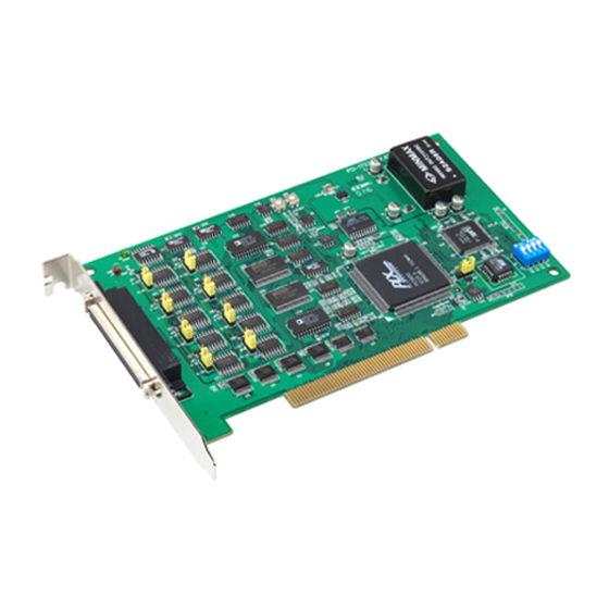
- Page 1 User Manual PCI-1723 16-bit, 8-ch Analog Output PCI Card with 16-ch Digital I/O...
- Page 2 Because of Advantech’s high quality-control standards and rigorous testing, most of our customers never need to use our repair service. If an Advantech product is defec- tive, it will be repaired or replaced at no charge during the warranty period. For out- of-warranty repairs, you will be billed according to the cost of replacement materials, service time and freight.
- Page 3 This product has passed the CE test for environmental specifications when shielded cables are used for external wiring. We recommend the use of shielded cables. This kind of cable is available from Advantech. Please contact your local supplier for ordering information.
- Page 4 PCI-1723 User Manual...
-
Page 5: Table Of Contents
Unpacking ....................8 Driver Installation ..................9 Hardware Installation ................9 Device Setup & Configuration ..............9 Figure 2.1 PCI-1723 Device Settings ........10 Figure 2.2 The Device Setting Page.......... 10 Figure 2.3 PCI-1723 Device Testing.......... 11 Chapter Signal Connections ......13... - Page 6 PCI-1723 User Manual...
-
Page 7: Chapter 1 Introduction
Chapter Introduction This chapter introduces PCI-1723 and its typical applications. Sections include: Features Applications Installation Guide Software Overview Roadmap Accessories... -
Page 8: Features
BoardID Switch The PCI-1723 has a built-in DIP switch that helps define each card’s ID when multi- ple PCI-1723 cards have been installed on the same PC chassis. The BoardID set- ting function is very useful when building a system with multiple PCI-1723 cards. With the correct BoardID settings, you can easily identify and access each card during hardware configuration and software programming. -
Page 9: Applications
Programmable current sink Servo control Multiple loop PID control Installation Guide Before you install your PCI-1723 card, please make sure you have the following nec- essary components: PCI-1723 card PCI-1723 user manual Driver software Advantech DAQNavi software (available for download from the Advantech website) ... -
Page 10: Software Overview
Figure 1.1 Installation Flow Chart Software Overview Advantech offers a rich set of DLL drivers, third-party driver support, and application software to help fully exploit the functions of your PCI-1723 card: Device Drivers Advantech DAQNavi DAQNavi Software Advantech’s DAQNavi software includes device drivers and a software development kit (SDK), which features a comprehensive I/O function library to boost application performance. -
Page 11: Daqnavi Device Driver Programming Roadmap
Advantech Navigator. Programming with DAQNavi Device Drivers Function Library Advantech DAQNavi Device Drivers offer a rich function library that can be utilized in various application programs. This function library consists of numerous APIs that support many development tools, such as Visual Studio.NET, Visual C++, Visual Basic, Delphi and C++ Builder. -
Page 12: Accessories
Drivers error, you can pass the error, you can check the error code and error descrip- tion within the Error Control of each function in the DAQNavi SDK Manual. Accessories Advantech offers a complete set of accessory products to support the PCI-1723 card. These accessories include: Wiring Cables ... -
Page 13: Chapter 2 Installation
Chapter Installation This chapter provides a packing item checklist, proper instructions for unpacking, and step-by-step procedures for both driver and card installation. Sections include: Unpacking Driver Installation Hardware Installation Device Setup & Configuration... -
Page 14: Unpacking
Unpacking After receiving your PCI-1723 package, inspect the contents. The package should include the following items: PCI-1723 card Startup Manual The PCI-1723 card has certain electronic components vulnerable to electrostatic dis- charge (ESD). ESD can easily damage the integrated circuits and certain compo- nents if preventive measures are ignored. -
Page 15: Driver Installation
Touch the metal part on the surface of your computer to neutralize any static electricity that might be on your body. Insert the PCI-1723 card into the PCI interface. Hold the card only by its edges and carefully align it with the slot. Insert the card firmly into place. Use of exces- sive force must be avoided;... - Page 16 You can then view the device(s) already installed on your system (if any) in the Installed Devices list box. If the software and hardware installation are com- pleted, you will see PCI-1723 card in the Installed Devices list. Figure 2.1 PCI-1723 Device Settings Configuring the Device Please go to Device Setting to configure your device.
- Page 17 After your card is properly installed and configured, you can go to the Device Test page to test the hardware using the testing utility supplied. Figure 2.3 PCI-1723 Device Testing For more detailed information, please refer to the DAQNavi SDK Manual or the User Interface Manual in the Advantech Navigator.
- Page 18 PCI-1723 User Manual...
-
Page 19: Chapter 3 Signal Connections
Chapter Signal Connections This chapter provides useful information about how to connect input and output signals to the PCI-1723 card via the I/O connec- tor. Sections include: Overview Board ID Settings Signal Connections Field Wiring Considerations... -
Page 20: Overview
This chapter provides useful information about how to connect input and output signals to the PCI-1723 via the I/O connector. Switch and Jumper Settings Please refer to Figure 3.1 for jumper and switch locations on PCI-1723. Figure 3.1 Connector and Switch Location PCI-1723 User Manual... -
Page 21: Board Id (Sw1)
3.2.1 Board ID (SW1) The PCI-1723 has a built-in DIP switch (SW1), which is used to define each card’s board ID. When there are multiple cards on the same chassis, this board ID switch is used to set each card’s device number. -
Page 22: Signal Connections
Signal Connections Pin Assignments The I/O connector on the PCI-1723 is a 68-pin connector that enables you to connect to accessories with the PCL-10168 shielded cable. Figure 3.2 shows the pin assignments for the 68-pin I/O connector on the PCI-1723, and Table 3.3 shows its I/O connector signal description. -
Page 23: I/O Connector Signal Description
14, 17, 19, 22, 24, 27, 29, 32,48, AGND Analog ground 51, 53, 56, 58, 61, 63, 66 DGND 5, 39 Digital ground Others 2 ~ 4, 15, 20, 25,30, 34,36 ~ 38, No connect 49, 54, 59, 64, 68 PCI-1723 User Manual... -
Page 24: Analog Output Connections
3.3.2 Analog Output Connections The PCI-1723 provides 8 channels of analog output (AO) signal generation with out- put ranges of ±10 V, 0 ~ 20 mA, and 4 ~ 20 mA. The output range of each channel can be configured independently by using dedicated pins or jumper. -
Page 25: Digital Input/Output Connections
LED shown in Figure 3-5. Caution! Exceeding the maximum input voltage ratings, which are listed in “Appendix A Specifications”, can damage the PCI-1723 and the com- puter. Advantech is not liable for any damage resulting from such signal connections. Field Wiring Considerations... - Page 26 PCI-1723 User Manual...
-
Page 27: Appendix A Specifications
Appendix Specifications... -
Page 28: Function Block
Voltage output Accuracy Offset Error < ±6 LSB <±0.1% of FSR (after manual calibration) Gain Error <±3% of FSR (without manual calibration) Current output Accuracy <±0.1% of FSR (after manual calibration) Gain Error <±3% of FSR (without manual calibration) PCI-1723 User Manual... -
Page 29: Digital Input/Output
(6.6 × 3.9 in. Typical +5 V @ 400mA Power Consumption Max. +5 V @ 820mA Operating 0~60°C (32~140°F) Temperature Storage -40 ~ 70°C (-40 ~ 158°F) Operating 10~90%RH non-condensing Relative Humidity Storage 5~95%RH non-condensing Certifications CE/FCC certified PCI-1723 User Manual... - Page 30 No part of this publication may be reproduced in any form or by any means, electronic, photocopying, recording or otherwise, without prior written permis- sion of the publisher. All brand and product names are trademarks or registered trademarks of their respective companies. © Advantech Co., Ltd. 2019...
Need help?
Do you have a question about the PCI-1723 and is the answer not in the manual?
Questions and answers