Table of Contents
Advertisement
Quick Links
Advertisement
Table of Contents

Related Manuals for Advantech PCIE-1680


Summary of Contents for Advantech PCIE-1680
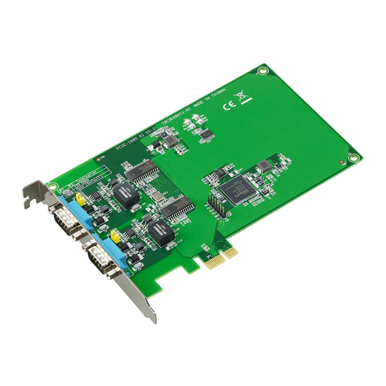
- Page 1 User Manual PCIE-1680 2-Port CAN-Bus PCIE card with Isolation Protection...
- Page 2 Because of Advantech’s high quality-control standards and rigorous testing, most of our customers never need to use our repair service. If an Advantech product is defec- tive, it will be repaired or replaced at no charge during the warranty period. For out- of-warranty repairs, you will be billed according to the cost of replacement materials, service time, and freight.
- Page 3 This product has passed the CE test for environmental specifications when shielded cables are used for external wiring. We recommend using shielded cables. This type of cable is available from Advantech. Please contact your local supplier for ordering information. FCC Class A This equipment has been tested and found to comply with the limits for a Class A dig- ital device, pursuant to Part 15 of the FCC rules.
- Page 4 Don't touch any components on the CPU card or other cards while the PC is on. Disconnect power before making any configuration changes. The sudden rush of power as you connect a jumper or install a card may damage sensitive elec- tronic components. PCIE-1680 User Manual...
-
Page 5: Table Of Contents
Hardware Installation ......11 Initial Inspection ..................12 Connector and Jumper Locations & Settings.......... 13 Figure 3.1 PCIE-1680 CAN-bus board silk screen ....13 Table 3.1: PCIE-1680 Board Silk Screen ........13 3.2.1 How to Set Jumpers..............13 Figure 3.2 How to set jumpers........... 13 3.2.2... - Page 6 PCIE-1680 User Manual...
-
Page 7: Chapter 1 Introduction
Chapter Introduction This chapter provides a general description of the PCIE-1680. Sections include: Introduction Features Specifications Ordering Information... -
Page 8: Introduction
Introduction PCIE-1680 is a special purpose communication card that offers connectivity to Con- troller Area Networks (CAN) on your PC. With its built-in CAN controllers, PCIE-1680 provides bus arbitration and error detection with an automatic transmission repetition. This drastically reduces the chance of data loss and ensures system reliability. You can run both CAN controllers independently at the same time. -
Page 9: Specifications
Operating Temperature: 0 ~ 70° C Storage Temperature: -40 ~ 85°C (-40 ~ 185°F) Operating Humidity: 5 ~ 95% Relative Humidity, non-condensing Ordering Information PCIE-1680-B: 2-Port CAN-Bus PCIE card with Isolation Protection Accessories OPT1-DB9E-AE: DB9 to 10-pin wiring board PCIE-1680 User Manual... - Page 10 PCIE-1680 User Manual...
-
Page 11: Chapter 2 Driver And Advantech Device Manager
Chapter Driver and Advantech Device Manager Installation This chapter shows how to install the driver and Advantech Device Manager. Sections include: Advantech Device Manager/ Driver Installation User API descriptions... -
Page 12: Driver Download
Driver Download Driver packages can be found on the Advantech Support Portal (https://www.advant- ech.com/support). Search for PCIE-1680 on the support portal and you’ll get the XNavi installer after the download session finishes. For a Linux driver, please down- load from Linux driver link directly. -
Page 13: Driver Installation In Windows System Via Xnavi
Driver Installation in Windows System via XNavi The Windows driver for PCIE-1680 are included in drivers of COM/CAN series. You only need to install the drivers for CAN series via XNavi installer, so that PCIE-1680 will be recognized in your system. -
Page 14: Driver Installation In Linux
The CAN driver installation should be done in console mode. You should manage all the installation actions via terminal. All the instructions and information are in README files, which are included along with both driver packages. Follow the instructions in the Installation section to install the drivers correctly. PCIE-1680 User Manual... -
Page 15: User Api Descriptions
User API descriptions Download the products user API description from Advantech’s website. http:// www.advantech.com/ Follow the steps below to search Advantech’s user API description. Go to http://www.advantech.com/, then search for the product. Click the Manual/ Driver/ BIOS/ FAQ hyperlink PCIE-1680 User Manual... - Page 16 Click the driver to download it. Users can download drivers and user API manu- als from this page. PCIE-1680 User Manual...
-
Page 17: Chapter 3 Hardware Installation
Chapter Hardware Installation This chapter covers inspection and installation of hardware and drivers. Sections include: Initial Inspection Connector and Jumper Locations & Settings Card Installation... -
Page 18: Initial Inspection
It should be free of marks and scratches and in perfect working order when received. As you unpack the PCIE-1680, check for signs of shipping damage (damaged box, scratches, dents, etc.). If it is damaged or it fails to meet specifications, notify our ser- vice department or your local sales representative immediately. -
Page 19: Connector And Jumper Locations & Settings
Connector and Jumper Locations & Settings Figure 3.1 PCIE-1680 CAN-bus board silk screen Table 3.1: PCIE-1680 Board Silk Screen Item Description CN2, CN3 DB-9 Male Connector JP1, JP2 Terminating Resistor Jumper 3.2.1 How to Set Jumpers You configure your card to match the needs of your application by setting jumpers. A jumper is the simplest kind of electric switch. -
Page 20: Terminating Resistor Setup (Jp1)
Terminating Resistor Setup (JP1) You can set the terminating resistor if necessary to match impedance. Each port has a separate resistor setting located near the corresponding transceiver. Table 3.2: PCIE-1680 Terminating Resistor Jumper Setting Status Value of Terminating Resistor ( Ω... -
Page 21: Chapter 4 Pin Assignments And Wiring
Chapter Pin Assignments and Wiring This chapter covers the pin assignment for the CAN connec- tor, and the wiring of the two transmission wires. Sections include: Pin Assignments... -
Page 22: Pin Assignments
Figure 4.1 shows the pin assignment for the card’s male DB-9 connectors and corre- sponding pin assignments of female DB-9 connectors of the cable. Figure 4.1 PCIE-1680 DB-9 connector pin assignments Figure 4.2 PCIE-1680 DB-9 connector schematics The CAN standard supports half–duplex communication. This means that just two wires are used to transmit and receive data. - Page 23 PCIE-1680 User Manual...
- Page 24 No part of this publication may be reproduced in any form or by any means, electronic, photocopying, recording or otherwise, without prior written permis- sion of the publisher. All brand and product names are trademarks or registered trademarks of their respective companies. © Advantech Co., Ltd. 2023...
Need help?
Do you have a question about the PCIE-1680 and is the answer not in the manual?
Questions and answers