Table of Contents
Advertisement
Quick Links
Advertisement
Table of Contents

Related Manuals for Advantech PCI-1762


Summary of Contents for Advantech PCI-1762
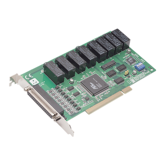
- Page 1 User Manual PCI-1762 16-ch Relay & 8-ch Isolated Digital Input PCI Card...
- Page 2 No part of this manual may be reproduced, copied, translated or transmitted in any form or by any means without the prior written permission of Advantech Co., Ltd. Information provided in this manual is intended to be accurate and reliable. How- ever, Advantech Co., Ltd.
-
Page 3: Declaration Of Conformity
EMI leakage, we strongly recommend the use of CE-compliant industrial enclo- sure products. Technical Support and Assistance Visit the Advantech web site at www.advantech.com/support where you can find the latest information about the product. Contact your distributor, sales representative, or Advantech's customer service center for technical support if you need additional assistance. -
Page 4: Safety Instructions
The sound pressure level at the operator's position according to IEC 704-1:1982 is no more than 70 dB (A). DISCLAIMER: This set of instructions is given according to IEC 704-1. Advantech disclaims all responsibility for the accuracy of any statements contained herein. -
Page 5: Table Of Contents
Contents Chapter Overview..........1 Introduction ....................2 1.1.1 PCI-1762 16-ch Isolated Digital Input and 16-ch Relay Output Card Features ....................2 Applications....................3 Installation Guide ..................3 Figure 1.1 Installation Flow Chart ..........4 Software Overview ..................4 Accessories....................5 Chapter Installation..........7... - Page 6 Interrupt Status Register - BASE+6H and BASE+7H ......28 Table C.5: Register for Interrupt Status ........28 Interrupt Control Register - BASE+6H and BASE+7H......29 Table C.6: Register for Interrupt Control........29 Appendix D Flow Chart ......... 31 Flow Chart....................32 PCI-1762 User Manual...
-
Page 7: Chapter 1 Overview
Chapter Overview... -
Page 8: Introduction
Board ID The PCI-1762 has a built-in DIP switch that helps define each card’s ID when multi- ple PCI-1762 cards have been installed on the same PC chassis. The board ID set- ting function is very useful when users build their system with multiple PCI-1762... -
Page 9: Applications
When the system has undergone a hot reset (i.e. without turning off the system power), the PCI-1762 can either retain outputs values of each channel, or return to its default configuration as open status, depending on its on-board jumper setting. This function protects the system from wrong operations during unexpected system resets. -
Page 10: Figure 1.1 Installation Flow Chart
Start to write your own application Figure 1.1 Installation Flow Chart Software Overview Advantech offers a rich set of DLL drivers, third-party driver support and application software to help fully exploit the functions of your PCI-1762 card: DLL driver (on the companion CD-ROM) ... -
Page 11: Accessories
Appendix C, Register Structure and Format. Accessories Advantech offers a complete set of accessory products to support the PCI-1762 cards. These accessories include: Wiring Cable The PCL-10162 shielded cable is specially designed for PCI-1762 cards to provide high resistance to noise. - Page 12 PCI-1762 User Manual...
-
Page 13: Chapter 2 Installation
Chapter Installation... -
Page 14: Unpacking
Startup Manual Switch and Jumper Settings The PCI-1762 card has one function switch and two jumper settings. The following sections tell how to configure the card. You may want to refer to the figure below for help in identifying card components. -
Page 15: Table 2.1: Summary Of Jumper Settings
Table 2.2: Summary of jumper settings for relay Relay Output channel Corresponding Jumper JP10 JP11 JP12 JP13 JP14 JP15 JP16 JP17 JP18 JP19 Setting the time to reset the relay outputs Some users will want the capability of clearing each relay output when PCI-1762 User Manual... -
Page 16: I/O Connectors
Complete loss of power to the chip clears the chip memory. Thus, no matter how JP2 is set, if the power to the PCI-1762 is disconnected, the relay initial power-on state will be “OFF” (NC or NO, depending on the user’s settings). -
Page 17: Driver Installation
Driver Installation We recommend you install the driver before you install PCI-1762 card into your sys- tem, since this will guarantee a smooth installation process. The 32-bit DLL driver Setup program for the PCI-1762 card is included on the companion CD-ROM that is shipped with your DA&C card package. -
Page 18: Figure 2.4 Driver Setup Options
Figure 2.4 Driver Setup Options For further information on driver-related issues, an online version of the Device Driv- ers Manual is available by accessing the following path: Start/Programs/Advantech Automation/Device Manager/Device Drivers Manual Hardware Installation Note! Make sure you have installed the driver first before you install the card (please refer to 2.4 Driver Installation) -
Page 19: Figure 2.5 Device Name On The Device Manager
2. Plug in the power cord and turn on the computer. After the PCI-1762 card is installed, you can verify whether it is properly installed on your system in the Device Manager: Access the Device Manager through Control Panel/System/Device Manager. -
Page 20: Device Setup & Configuration
Device Setup & Configuration The Advantech Device Manager program is a utility that allows you to set up, config- ure and test your device, and later stores your settings on the system registry. These settings will be used when you call the APIs of Advantech Device Drivers. -
Page 21: Figure 2.7 Device Setting Dialog Box
Note! As we have noted, the device name 001:<PCI-1762 BoardID=0 I/ O=c400H> begins with a device number "001", which is specifically assigned to each card. The device number is passed to the driver to specify which device you wish to control. - Page 22 PCI-1762 User Manual...
-
Page 23: Chapter 3 Signal Connections
Chapter Signal Connections... -
Page 24: Overview
This chapter provides useful information about how to connect input and output signals to the PCI-1762 via the I/O connector. Isolated Digital Input Connections The PCI-1762 has 16 isolated digital input channels designated IDI0~IDI15. Each of isolated digital input channel accepts 10~50 V voltage inputs, and accept bi-directional input. -
Page 25: Relay Connections
Relay Connections After power on, the initial relay output status of PCI-1762 is shown as below: Figure 3.2 Relay Output Connection A write operation to I/O address, BASE +0, will change the output status of each relay. For example, if Bit 0 of BASE +0 is set "1" (logic high), relay 0, K0, will switch from position "NORMALLY CLOSED", NC0, to position "NORMALLY OPEN", NO0. - Page 26 PCI-1762 User Manual...
- Page 27 Appendix Specifications...
-
Page 28: Appendix A Specifications
+5V @ 250 mA (typical) +5V @ 620 mA (max.) Temperature Operating 0 ~ +60°C (32 ~ 140°F) Storage -20 ~ +70°C (-4 ~ 158°F) Relative Humidity 5 - 95 % RH non-condensing (refer to IEC 68-2-3) Certifications CE/FCC PCI-1762 User Manual... -
Page 29: Appendix B Block Diagram
Appendix Block Diagram... -
Page 30: Block Diagram
Block Diagram Appendix PCI-1762 User Manual... -
Page 31: Appendix C Register Structure And Format
Appendix Register Structure and Format... -
Page 32: Overview
BASE+0 is the card’s base address and BASE+7 is the base address plus seven bytes. Table C-1 shows the function of each register of the PCI-1762 or driver and its address relative to the card’s base address. Table C.1: Register Functions... -
Page 33: Relay I/O Registers - Base+0H And Base+1H
C.3 Relay I/O Registers - BASE+0H and BASE+1H The PCI-1762 offers 16-ch relay Actuators. These I/O channels use the input and output ports at addresses BASE+0 and BASE+1. Table C.2: Register for Relay Output Status Read Relay Output Status Bit #... -
Page 34: Board Id - Base+4H
Board ID - BASE+4H The PCI-1762 offers Board ID register BASE+4. With correct Board ID settings, user can easily identify and access each card during hardware configuration and software programming. Table C.4: Register for Board ID Read Board ID Bit #... -
Page 35: Interrupt Control Register - Base+6H And Base+7H
The interrupt can be triggered by a rising edge or falling edge of the interrupt signal, as determined by the value in this bit. Rising edge trigger Falling edge trigger Appendix PCI-1762 User Manual... - Page 36 PCI-1762 User Manual...
-
Page 37: Appendix D Flow Chart
Appendix Flow Chart... -
Page 38: Flow Chart
Flow Chart To write a command or confirm the command status, please follow the follow chart below. PCI-1762 User Manual... - Page 39 PCI-1762 User Manual...
- Page 40 No part of this publication may be reproduced in any form or by any means, electronic, photocopying, recording or otherwise, without prior written permis- sion of the publisher. All brand and product names are trademarks or registered trademarks of their respective companies. © Advantech Co., Ltd. 2011...
Need help?
Do you have a question about the PCI-1762 and is the answer not in the manual?
Questions and answers