
Related Manuals for Advantech PCIE-1761H


Summary of Contents for Advantech PCIE-1761H
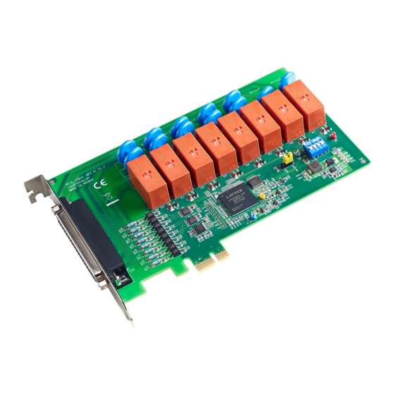
- Page 1 User Manual PCIE-1761H 8-Channel Relay and 8-Channel Isolated Digital Input PCI Express Card...
- Page 2 The documentation and the software included with this product are copyrighted 2018 by Advantech Co., Ltd. All rights are reserved. Advantech Co., Ltd. reserves the right to improve the products described in this manual at any time without notice. No part of this manual may be reproduced, copied, translated, or transmitted in any form or by any means without the prior written permission of Advantech Co., Ltd.The infor-...
- Page 3 EMI leakage, we strongly recommend the use of CE-compliant industrial enclo- sure products. Technical Support and Assistance Visit the Advantech web site at www.advantech.com/support to obtain the latest product information. Contact your distributor, sales representative, or Advantech's customer service center for technical support if you need additional assistance.
- Page 4 In accordance with the IEC 704-1:1982 standards, the sound pressure level at the operator's position does not exceed 70 dB (A). DISCLAIMER: These instructions are provided according to the IEC 704-1 standard. Advantech disclaims all responsibility for the accuracy of any statements contained herein. PCIE-1761H User Manual...
-
Page 5: Table Of Contents
Relay Connections .................. 12 Figure 3.2 Relay Output Connection ......... 12 Appendix A Specifications ........15 Isolated Digital Input................16 Digital Filter Time ..................16 Relay Output ................... 16 General Specifications ................17 Appendix B Block Diagram ........19 Block Diagram..................20 PCIE-1761H User Manual... - Page 6 PCIE-1761H User Manual...
-
Page 7: Chapter 1 Overview
Chapter Overview... -
Page 8: Introduction
Introduction Advantech’s PCIE-1761H is an 8-channel relay actuator and 8-channel isolated digi- tal input card for PCIE bus. Built with 8 on-board SPDT relays, PCIE-1761H is ideal for applications such as device ON/OFF control and power switching. Moreover, to ensure easy monitoring, each relay is equipped with a red LED to show its ON/OFF status. -
Page 9: Applications
Board ID The PCIE-1761H has a built-in DIP switch that helps define each card's ID when mul- tiple PCIE-1761H cards are installed on the same PC chassis. The board ID setting function is very useful when users build their system with multiple PCIE-1761H cards. -
Page 10: Software Overview
Software Overview Advantech offers multiple DLL drivers, third-party driver support, and application soft- ware to assist customers with fully exploiting the functions of the PCIE-1761H card: Device drivers (an be downloaded from the Advantech product page) LabVIEW driver ... -
Page 11: Chapter 2 Installation
Chapter Installation... -
Page 12: Unpacking
PCIE bus, or to clear relays only as part of a system bootup. The PCIE-1761H card satisfies both of these needs with the provision of jumper JP2. Depending on the application, this may allow relay outputs to be configured as “OFF”... - Page 13 Board ID (SW1) The PCIE-1761H card features a built-in DIP switch (SW1) that is used to define the Board ID for each card. When multiple cards are installed on the same chassis, the Board ID switch is useful for identifying each card’s device number. After installing PCIE-1761H cards, users can identify each card using their different device num- bers.
-
Page 14: I/O Connectors
I/O Connectors Pin Assignments The pin assignments for the 37-pin I/O connector on the PCIE-1761H card are shown in Figure 2.2. Description of Pin Use IDInA* (n = 0 ~ 7): Isolated digital input A IDInB*(n = 0 ~ 7):... -
Page 15: Device And Configuration
After which, the device settings are stored on the system registry and used when Advantech device driver APIs are employed. Setting Up the Device To install the I/O device for the PCIE-1761H card, run the Advantech Device Manager program (accessible via Start/Programs/Advantech Automation/ Device Manager/Advantech Device Manager). - Page 16 PCIE-1761H User Manual...
-
Page 17: Chapter 3 Signal Connections
Chapter Signal Connections... -
Page 18: Overview
(Vin). The figure below shows how to connect an external input source to one of the card's isolated input channels. Figure 3.1 Isolated Digital Input Connections Relay Connections After power on, the initial relay output status of the PCIE-1761H card should be as shown below. Figure 3.2 Relay Output Connection PCIE-1761H User Manual... - Page 19 PCIE-1761H User Manual...
- Page 20 PCIE-1761H User Manual...
-
Page 21: Appendix A Specifications
Appendix Specifications... -
Page 22: Isolated Digital Input
Max. Switching Voltage Contact Resistance 100mΩ max. Between coil and contacts 5000 V Breakdown Voltage Between open and contacts 1000 V Operating Time 7ms typical Release Time 2ms typical Life Expectancy 30 x 10 cycles @2A/250 V PCIE-1761H User Manual... -
Page 23: General Specifications
+3.3V @ 250 mA (typical) +3.3V @ 1600mA (max.) Temperature Operating: 0 ~ 60 °C (32 ~ 140 °F) Storage: -40 ~ 70 °C (-40 ~158 °F) Relative Humidity 5 - 95% RH non-condensing (refer to IEC 68-2-3) Certifications CE/FCC PCIE-1761H User Manual... - Page 24 PCIE-1761H User Manual...
-
Page 25: Appendix B Block Diagram
Appendix Block Diagram... -
Page 26: Block Diagram
Block Diagram Appendix PCI-1761 User Manual... - Page 27 PCI-1761 User Manual...
- Page 28 No part of this publication may be reproduced in any form or by any means, such as electronically, by photocopying, recording or otherwise, without prior written permission from the publisher. All brand and product names are trademarks or registered trademarks of their respective companies. © Advantech Co., Ltd. 2018...
Need help?
Do you have a question about the PCIE-1761H and is the answer not in the manual?
Questions and answers