Sign In
Upload
Manuals
Brands
Advantech Manuals
PCI Card
PCI-1601AU
Advantech PCI-1601AU Manuals
Manuals and User Guides for Advantech PCI-1601AU. We have
1
Advantech PCI-1601AU manual available for free PDF download: User Manual
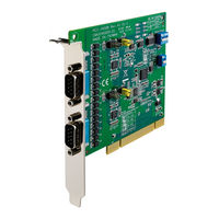
Advantech PCI-1601AU User Manual (106 pages)
Industrial Serial Communication Cards
Brand:
Advantech
| Category:
PCI Card
| Size: 2.52 MB
Table of Contents
Table of Contents
7
Chapter 1 Introduction
12
Description
12
Features
13
Specifications
13
Ordering Information
15
Accessories
17
Table 1.1:PCI Communication Cards Selection Guide
18
Chapter 2 Hardware Configuration
20
Initial Inspection
20
Figure 2.1: PCI-1601A/B Silk Screen
21
Jumper and Switch Locations
21
Figure 2.2:PCI-1601AU/BU Silk Screen
22
Figure 2.3:PCI-1602A/B Silk Screen
23
Figure 2.4:PCI-1602AU/BU Silk Screen
24
Figure 2.5:PCI-1602UP Silk Screen
25
Figure 2.6:PCI-1603 Silk Screen
26
Figure 2.7:PCI-1604UP Silk Screen
27
Figure 2.8:PCI-1610A/B Silk Screen
28
Figure 2.9:PCI-1610CU Silk Screen
29
Figure 2.10:PCI-1610AUP/UP Silk Screen
30
Figure 2.11:PCI-1610AJP Silk Screen
31
Figure 2.12:PCI-1611U Silk Screen
32
Figure 2.13:PCI-1612A/B Silk Screen
33
Figure 2.14:PCI-1612AU/U Silk Screen
34
Figure 2.15:PCI-1612CU Silk Screen
35
Figure 2.16:PCI-1620A/B Silk Screen
36
Figure 2.17:PCI-1620AU/U Silk Screen
37
Figure 2.18:PCI-1622CU Silk Screen
38
Jumper Settings
39
Figure 2.19:How to Set Jumpers
39
How to Set Jumpers
39
Default Settings
40
Table 2.1:PCI-1601/1602/1611/1612/1622 Default Set Ting
40
Figure 2.20:PCI-1603 Default Setting
40
Mode Selection by Jumper/Dip Settings
41
Figure 2.22:RS-422/485 Selection by Jumper Setting
41
Figure 2.23:PCI-1603 RS-232 Mode Jumper Setting
42
Figure 2.25:Active Mode Jumper Setting
42
Figure 2.26:Passive Mode Jumper Setting
43
Figure 2.27:Resistor Selection
44
Card Installation
45
Chapter 3 Driver Setup & Installation
48
Introduction
48
Driver Setup
48
Steps for Windows 98/2000/XP Driver Setup
48
Reboot System after Win98/2000/Xp Driver Setup
54
PCI Uarts Device Driver Installation
54
PCI Bridge Device Driver Installation
56
Verify Your Win98/2000/Xp Driver Setup
57
Configuring Serial Devices for Win 98/2000/XP
60
Configuring a PCI Uarts Device
62
Configuring a PCI Bridge Device
63
Configuring Ports
63
Remove PCI ICOM Series Device
64
Driver Uninstall
67
Chapter 4 ICOM Tools
70
Introduction
70
Installation
70
User Interface of ICOM Tools
71
Menu Bar
71
Tool Bar
72
Com Port Tab
73
Port Status
74
Message Logo
74
Tx Slide Bar
75
Performance Listing Area
75
Status Bar
75
Using the ICOM Tools Utility
76
Port Selection
76
Figure 4.1:ICOM Tools Program Window
76
Figure 4.2:Select Port Dialog Box
77
Figure 4.4:ICOM Tools User Interface
78
Configuring a Port
78
Figure 4.5:Test Information on the Performance Listing Area
79
Close Port
80
Exit the ICOM Tools Utility
80
Messages on Status Bar and Message Logo Area
81
Status Bar Messages
81
Message Logo Messages
82
Chapter 5 Pin Assignments and Wiring
84
Pin Assignments
84
Table 5.1:PCI-1601/1602 Male DB9 on Bracket
84
Figure 5.1:PCI-1601/1602 Pin Assignment
84
Pci-1601A/Au/B/Bu, Pci-1602A/Au/B/Bu
84
Pci-1602Up
85
Table 5.2:PCI-1602UP Male DB9 on Cable
85
Table 5.3:PCI-1602UP Female DB25 on Bracket
85
Pci-1603
86
Table 5.4:PCI-1603 Male DB9 on Bracket
86
Pci-1604Up
87
Table 5.5:PCI-1604 Male DB9 on Cable
87
Table 5.6:PCI-1604UP Female DB25 on Bracket
87
Pci-1610A/B/Cu
88
Table 5.7:PCI-1610A/B/CU Male DB9 on Cable
88
Table 5.8:PCI-1610A/B/CU Male DB25 on Cable
88
Table 5.9:PCI-1610A/B/CU Female DB37 on Bracket
89
Pci-1610Aup/Up
90
Table 5.10:PCI-1610AUP/UP Male DB9 on Cable
90
Pci-1610Aju
91
Table 5.12:PCI-1610AJU Male DB9 on Cable
91
Table 5.13:PCI-1610AJU RJ45 on Bracket
91
Pci-1611U
92
Table 5.14:PCI-1611U Male DB9 on Cable
92
Table 5.15:PCI-1611U Male DB25 on Cable
92
Table 5.16:PCI-1611U Female DB37 on Bracket
93
Pci-1612A/B/Au/U/Cu
94
Table 5.19:PCI-1612A/B/AU/U/CU Female DB37 on Bracket
95
Pci-1620A/B/Au/U
96
(Opt8Bp,Opt8C)
97
(Opt8Ap)
98
(Opt8Fp)
98
Table 5.25:PCI-1622CU Male DB9 on Cable (OPT8J)
99
Pci-1622Cu
99
Table 5.27:PCI-1622CU Female DB78 on Bracket
100
Wiring
102
Signal Wiring
102
Table 5.28:Terminal or PC (DTE) Connections
102
Table 5.29:Modem Connections
103
Table 5.30:Terminal Without Handshake
103
RS-422 Signal Wiring
104
Table 5.31:RS-422 DB9 Pin Assignment
104
RS-485 Signal Wiring
105
Figure 5.2:RS-485 Wiring Topology
105
Advertisement
Advertisement
Related Products
Advantech PCI-1601
Advantech PCI-1601A
Advantech PCI-1601B
Advantech PCI-1601BU
Advantech PCI-1602UP
Advantech PCI-1604UP
Advantech PCI-1602A
Advantech PCI-1602B
Advantech PCI-1602BU
Advantech PCI-1602AU
Advantech Categories
Motherboard
Computer Hardware
Desktop
Network Router
Touch Panel
More Advantech Manuals
Login
Sign In
OR
Sign in with Facebook
Sign in with Google
Upload manual
Upload from disk
Upload from URL