Table of Contents
Advertisement
Quick Links
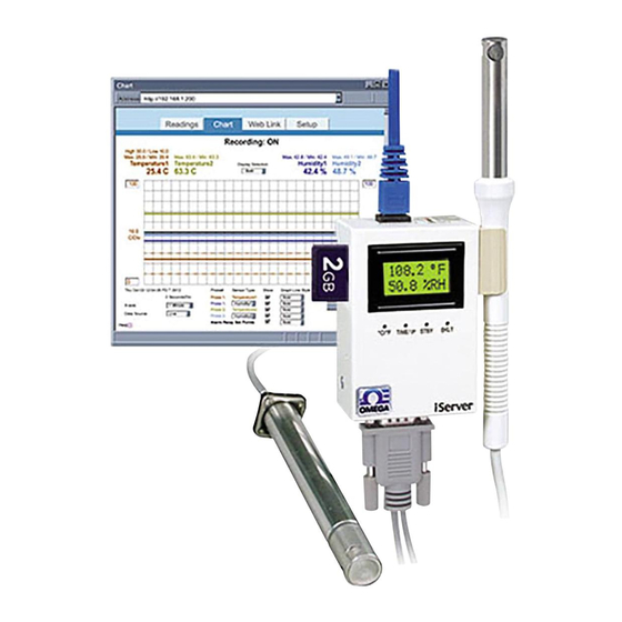
OMEGA iTHP-W-6
Wand Probe
A l l t r a d e m a r k s , b r a n d n a m e s , a n d b r a n d s a p p e a r i n g h e r e i n a r e t h e p r o p e r t y o f t h e i r r e s p e c t i v e o w n e r s .
• C r i t i c a l a n d e x p e d i t e d s e r v i c e s
• I n s t o c k / R e a d y - t o - s h i p
Artisan Scientific Corporation dba Artisan Technology Group is not an affiliate, representative, or authorized distributor for any manufacturer listed herein.
Limited Availability
Used and in Excellent Condition
Buy Today!
https://www.artisantg.com/88737-2
• We b u y y o u r e x c e s s , u n d e r u t i l i z e d , a n d i d l e e q u i p me n t
• F u l l - s e r v i c e , i n d e p e n d e n t r e p a i r c e n t e r
Advertisement
Table of Contents

Subscribe to Our Youtube Channel
Related Manuals for Omega iServer MicroServer iTHX-SD


Summary of Contents for Omega iServer MicroServer iTHX-SD
- Page 1 OMEGA iTHP-W-6 Wand Probe Limited Availability Used and in Excellent Condition Buy Today! https://www.artisantg.com/88737-2 A l l t r a d e m a r k s , b r a n d n a m e s , a n d b r a n d s a p p e a r i n g h e r e i n a r e t h e p r o p e r t y o f t h e i r r e s p e c t i v e o w n e r s .
- Page 2 User’ s Gui d e Shop online at omega.com e-mail: info@omega.com For latest product manuals: www.omegamanual.info Temperature + Humidity...
- Page 3 Fax: (203) 359-7700 e-mail: info@omega.com For Other Locations Visit omega.com/worldwide The information contained in this document is believed to be correct, but OMEGA accepts no liability for any errors it contains, and reserves the right to alter specifications without notice.
-
Page 4: Table Of Contents
TABLE OF CONTENTS Part 1: INTRODUCTION 1.1 Safety and EMC Considerations ..............2 1.2 Before You Begin .....................2 1.3 Description .......................2 Part 2: HARDWARE 2.1 Dimensions ......................5 2.2 Wall Mounting ....................6 2.3 Parts of the iServer Unit ................7 2.4 Disassembly Instruction ................8 2.5 Network Communication Interfaces ............ - Page 5 TABLE OF CONTENTS (continued) 4.4.5 Security ..................32 4.4.6 Recording ..................34 4.4.6.1 Start Recording ............... 34 4.4.6.2 Status ..................36 4.4.6.3 Data Retrieval ................37 4.4.6.4 Format SD Card ..............38 4.4.7 System ................... 38 4.4.7.1 Reboot ..................38 4.4.7.2 Defaults ...................
- Page 6 LIST OF FIGURES: Figure 1.1 iServer and iLD Big Display on the Ethernet Network ......4 Figure 2.1 Dimensions ....................5 Figure 2.2 Wall Mounting ....................6 Figure 2.3 Parts of the iServer Unit ................7 Figure 2.4 Opening the Unit ................... 8 Figure 2.5 RJ45 Pinout ....................
- Page 7 LIST OF FIGURES (continued) Figure 4.41 iLog Software Logging Data ..............54 Figure C.1 ARP Commands and Responses ............. 58 Figure G.1 Java 1.7 Screen Shot ................. 63 Figure H.1 RH Accuracy Chart ..................65 Figure H.2 Temperature Accuracy Chart ..............65 Figure H.3 Normal Range .....................
-
Page 8: Notes, Warnings And Cautions
NOTES, WARNINGS and CAUTIONS Information that is especially important to note is identified by the following labels: ARNING or CAUTION NOTE: Provides you with information that is important to successfully setup and use the iServer. CAUTION: Tells you about the risk of electrical shock. CAUTION: Risk of danger. -
Page 9: Part 1: Introduction
PART 1 INTRODUCTION 1.1 Safety and EMC Considerations Refer to the CE Approvals Section. EMC Considerations Whenever EMC is an issue, always use shielded cables. Never run signal and power wires in the same conduit. Use twisted-pair wires for signal connections. Install Ferrite Bead(s) on signal wires close to the instrument if EMC problems persist. - Page 10 1.3 Description (continued) Back-up Battery. The iServer comes with a universal 100 to 240 Vac power adapter. A standard 9 Volt Alkaline battery (also included) allows the device to continue recording data for 60 hours (at one minute interval setting) without external ac power (such as a power outage).
-
Page 11: Figure 1.1 Iserver And Ild Big Display On The Ethernet Network
1.3 Description (continued) Award-winning Technology. The iServer is simple to install and use. It features award winning technology that requires no special software except a Web browser. The iServer connects to an Ethernet Network with a standard RJ45 connector and sends data in standard TCP/IP packets. -
Page 12: Part 2 Hardware
PART 2 HARDWARE 2.1 Dimensions 12.7 [0.50 ] If unit is to be mounted on a flat 82.6 [3.25] surface, you may 19.1 [0.75] take the bottom rubber feet off the unit. 61.6 [2.42] Dimensions are in mm with inches in [ ]. 3.0 [0.12] 36.6 [1.44] 2.54 [0.10]... -
Page 13: Wall Mounting
2.2 Wall Mounting Position unit where required. Mark and drill the two #4 screw holes. After bracket is mounted on the wall, align back of unit over the three bracket clips, once engaged, slide downward, the unit will snap in place. 61.6 [2.42] 11.7 [0.46 ] 38.1 [1.50]... -
Page 14: Parts Of The Iserver Unit
2.3 Parts of the iServer Unit The 9V battery is the back-up power for the recording function only. Figure 2.3 Parts of the iServer Unit Table 2.1 Parts of iServer Unit ETHERNET RJ45 interface for 10/100BASE-T connection. RESET Button: Momentary (Push and Release) resets power on unit; Push and Hold for 10 seconds to reset unit to factory defaults and reset power. -
Page 15: Disassembly Instruction
2.3 Parts of the iServer Unit (continued) STBY Button: 1) Stops the recording 2) Press before ejecting Flash Card. NOTE: display will show “Safe to Eject SD” after button has been pressed. BKLT Button: Push and Hold to display Backlight on LCD when it is running on the back-up battery (backlight is always on while running on the ac adapter). -
Page 16: Network Communication Interfaces
2.5 Network Communication Interfaces 2.5.1 10/100 BASE-T RJ-45 Pinout The 10/100BASE-T Ethernet network Name Description system is used in the iServer for +Transmit Data network connectivity. The 10 Mbps - Tx -Transmit Data or 100 Mbps twisted-pair Ethernet +Receive Data system operates over two pairs of Not Connected wires. -
Page 17: Part 3 Network Configuration
PART 3 NETWORK CONFIGURATION 3.1 Network Protocols The iServer can be connected to an Ethernet network communicating through standard IP protocols including TCP, UDP, SNMP, SMTP, ARP, HTTP (WEB access), DNS, DHCP, ICMP, SNTP, and Telnet. 3.2 Ethernet (MAC) Address MAC (Media Access Control) address is a unique hardware number for Ethernet devices like computers, network switches, print servers, etc. -
Page 18: Dhcp
3.3 DHCP DHCP, Dynamic Host Configuration Protocol, enables computers and network devices to receive their IP configurations from a DHCP server. If DHCP is enabled on your iServer, as soon as the iServer that is connected to the network is powered on, there will be an exchange of information between the iServer and the DHCP server. -
Page 19: Port Number
3.6 Port Number All TCP connections are defined by the IP address and a port number. A port number is an internal address that provides a TCP/IP interface between an application software on a computer and a device on the network or between two devices on the network. There are two default TCP port (socket) numbers assigned to the iServer: 1) Port 2000: Once a TCP connection is made to the iServer using port 2000 or any port number that is configured on the iServer for Local Port (see Network menu,... -
Page 20: Arp Httpget Commands (Method 2)
4.1.2 ARP HTTPget Commands (Method 2) (continued) The above IP address of 128.100.101.76 is an example to show how these commands work. To get a valid IP address on your network you need to consult with your IT department. Figure 4.1 shows the screen shot of an actual DOS window with the above commands executed. -
Page 21: Figure 4.2 Connecting Computer Directly To Iserver
4.1.3 Direct Connection (Method 3) (continued) After connecting the Ethernet Cable iServer to computer, power it on. Computer’s LINK/ACT LED should be Ethernet Port SOLID green (RJ45 connection) 100 BASE-T LINK / ACT DHCP RECORDING iServer with default IP address Plug in the of 192.168.1.200 Power Adapter... -
Page 22: Figure 4.5 Changing Tcp/Ip Properties On Your Computer
4.1.3 Direct Connection (Method 3) (continued) Fill out the feilds for the IP address 192.168.1.100 and Select “Internet Protocol 3) Click on “Properties” Subnet mask 255.255.255.0 (TCP/IP)” and click on button as indicated below. Press “Properties” button OK and also on all other remaining windows. -
Page 23: Figure 4.7 Pinging The Iserver From Ms-Dos Prompt
4.1.3 Direct Connection (Method 3) (continued) To verify a good connection to the iServer, from a DOS prompt on your computer type “ping 192.168.1.200” and press Enter. You should get a reply as shown in Figure 4.7. If you don’t receive a reply it means that you do not have a network connection between your PC and the iServer. -
Page 24: Iconnect Software (Method 4)
4.1.4 iConnect Software (Method 4) The iServer can be assigned an IP Address by using the iConnect software. Download the iConnect software from the website listed on the cover of this manual (software section). Install iConnect software on a networked PC. This software is compatible with Windows 95, 98, NT, 2000, and XP. -
Page 25: Figure 4.9 Accessing The Iserver's Using Iconnect
4.1.4 iConnect Software (Method 4) (continued) To access the iServer for Configuration: Click on the “View Webpage” button, you will access the iServer’s welcome page. To take advantage of the iServer’s full capability use any standard web browser to access the iServer’s web pages as described in Section 4.2. Readings Chart Setup... -
Page 26: Access And Configuration Using A Web Browser
4.2 Access and Configuration Using a Web Browser Start your web browser. In the URL field, type http://192.168.1.200 (iServer’s default IP address). The Welcome Page, will be displayed. iTHX-SD Welcome Page Address http://192.168.1.200 Readings Chart Setup Web Link Figure 4.10 iServer Welcome Page In order to access the iServer’s web pages, users may be prompted for a password, as shown below. -
Page 27: Setup
4.4 Setup Clicking the Setup button on the Welcome page (see Figure 4.10) will provide access to the Menu Panel (see Figure 4.12). Using this Panel you can configure the iServer entirely. 4.4.1 Overview Once the Administrator password is entered, the Overview page will appear which provides a summary of important parameters within the iServer. -
Page 28: Network
4.4.2 Network This menu provides network configurations including IP parameters and Ethernet interface options. Fields are described below. 4.4.2.1 IP Configuration Network Address http://192.168.1.200 Readings Web Link Setup IP Configuration Ethernet Port DHCP Overview Network 00:03:34:00:b8:70 MAC Address Configuration IP Address 192.168.1.200 Management Subnet Mask... - Page 29 4.4.2.1 IP Configuration (continued) Gateway Address – This points to the router that forwards traffic to a destination address outside of the subnet on which the iServer resides. This is the IP address of the router which functions as a gateway. When DHCP is enabled this field will be dimmed. The iServer’s default Gateway address is 0.0.0.0.
-
Page 30: Ethernet Port
4.4.2.2 Ethernet Port Ethernet Port Address http://192.168.1.200 Readings Web Link Setup IP Configuration Ethernet Port Overview Auto-Negotiation Network Speed 100 Mbps 10 Mbps Configuration Duplex Full Half Management Security Recording Save Changes Reset System Diagnostics Log Out Figure 4.14 Network: Ethernet Configuration Auto-Negotiation –... -
Page 31: Figure 4.15 Network: Ethernet Configuration
4.4.3.1 Data and Time (continued) Date and Time Address http://192.168.1.200 Readings Web Link Setup Date and Time Server Sensors Alarm Relays Overview Date and Time Network Current Date 2099/01/01 (yyyy/mm/dd) Configuration Current Time 00:00:00 Management Change Date and Time Security Recording Time Server System... -
Page 32: Server
4.4.3.2 Server Server Address http://192.168.1.200 Readings Web Link Setup Date and Time Server Sensors Alarm Relays Server Overview Network Server Type Command Configuration Interval secs Management Time Stamp Security Disconnect After Data Sent Recording System Diagnostics Save Changes Reset Log Out Figure 4.16 Configuration Menu: Server Server Type –... -
Page 33: Figure 4.17 Configuration Menu: Sensors
4.4.3.3 Sensors (continued) End Character – This means that the iServer will send a character (in Hex) after the value for each variable. This will apply to either Continuous or Command mode. Once the value is selected, it will be a global change for all readings. The default is set for 0D (Hex representation of <CR>). -
Page 34: Alarm Relays
4.4.3.3 Sensors (continued) Offset – If it’s determined that the reading is slightly off, this field can be used to manually assign a numerical value to adjust the reading. The offset can be a positive or a negative number with one decimal point. The temperature offset value must be assigned after the Unit (C or F) is selected. -
Page 35: Figure 4.18 Configuration Menu: Alarm Relays
4.4.3.4 Alarm Relays (continued) Alarm Relays Address http://192.168.1.200 Readings Web Link Setup Date and Time Server Sensors Alarm Relays Overview Probe Probe Network Configuration Relay 1 Relay 2 Temperature Dew Point Alarm status with Management Description Description R1alarm1 R2alarm2 the associated set Security Status Status... -
Page 36: Management
4.4.4 Management This page provides the iServer’s email, SNMP and alarm settings. SNMP (Simple Network Management Protocol) is the protocol used by network management systems to communicate with network devices that respond to SNMP connections for the purpose of problem detections and corrections. If SNMP and/or SMTP features are desired, please make sure iServer’s network setting as well as SNMP trap server and SMTP mail server are setup properly. -
Page 37: Smtp Simple Mail Transfer Protocol
4.4.4.1 Setup (continued) SNMP Trap Server – This field contains the IP address of the SNMP trap server located somewhere on the network. The trap server listens for SNMP traps coming from the iServer when there is an alarm condition (refer to Alarms Section 4.4.4.2 under the Management page). -
Page 38: Figure 4.20 Management Menu: Alarms
4.4.4.2 Alarms (continued) Alarms Address http://192.168.1.200 Readings Web Link Setup Setup Alarms Overview Events Email SNMP Trap Network Probe 1 Configuration Management Temperature Low Low 0.0 High 0.0 Security High Humidity Recording High Dewpoint System Diagnostics Probe 2 Log Out Low or High Temp High... -
Page 39: Security
Low Battery – If the 9V battery lowers to about 7V, the iServer will prompt an alarm. Relay 1 Activated – If relay 1 is activated the iServer will prompt an alarm. See Alarm Relays section under the Configuration page (Section 4.4.3.4). Relay 2 Activated –... - Page 40 Login Password – To access Readings, Chart, and Web Link menus this password is required. The password length can be up to 16 alphanumeric case-sensitive characters. To change the password click on Change. Empty box means no password is required. The default Login Password is 12345678. Administrator Password –...
-
Page 41: Recording
4.4.6 Recording This section includes all the parameters and settings for data recording, SD flash card and recording status, data retrieval, and formatting the SD card. Fields are described below. 4.4.6.1 Start Recording Start Recording Address http://192.168.1.200 Readings Web Link Setup Start Recording Status Data Retrieval... - Page 42 4.4.6.1 Start Recording (continued) Category – The options are Continuous and Scheduled. In Continuous recording Start Date and Start Time fields are required. If there is not an End Date and End Time, the recording will continue non-stop. In Scheduled recording, any of the days can be selected and the recording will take place only on those days.
-
Page 43: Status
4.4.6.2 Status This page describes the Recording and SD flash card status. All the fields on this page are read-only. Status Address http://192.168.1.200 Readings Web Link Setup Start Recording Status Data Retrieval Format SD Card Current Date: 2099/01/01 Current Time: 00:00:00 Overview Recording Status... -
Page 44: Data Retrieval
4.4.6.3 Data Retrieval This page can be used to retrieve the recorded data from the SD flash card and save it into an ASCII file. Using the Retrieve EndDate field select the date (year, month, and day) that is the end date for the retrieved data. -
Page 45: Format Sd Card
4.4.6.4 Format SD Card Clicking on Format SD Card button will start formatting the flash card inside the iServer. Formatting the SD card will erase all data on the card. Allow up to 2 minutes for format to be completed which then it will display “SD Card Formatted”. Format SD Card Address http://192.168.1.200... -
Page 46: Defaults
4.4.7.2 Defaults Clicking on this button will put the iServer back to its default settings. Defaults Address http://192.168.1.200 Readings Web Link Setup Reboot Defaults Upgrade Download Configuration Upload Configuration Overview Network Restore Factory Defaults Configuration Management Security Recording System Diagnostics Figure 4.27 System: Defaults Log Out 4.4.7.3 Upgrade... -
Page 47: Download Configuration
4.4.7.3 Upgrade (continued) Either one of the above options will make you the only user on that iServer. Set the iServer to default settings after the firmware is upgraded. See Section 4.4.7.2 on how to set the iServer to default settings. Applying default settings will change the iServer’s settings to factory defaults. -
Page 48: Upload Configuration
4.4.7.5 Upload Configuration Upload Configuration Address http://192.168.1.200 Readings Web Link Setup Reboot Defaults Upgrade Download Configuration Upload Configuration Overview Network Configuration Browse... Management Upload Configuration File *.cfg Security Recording System Please make sure no other clients are connected to the device. Diagnostics Consult manual for complete instructions. -
Page 49: Readings
4.5 Readings This page displays temperature, humidity, dew point, and the status of the alarm relays and recording. It can be displayed either as an HTML page or a Java applet. 4.5.1 HTML Figure 4.32 Readings: HTML - Shown with Probe 1 and 2 Enabled Refresh –... -
Page 50: Java
4.5.2 Java If Java option is chosen installation of Java Runtime is required (refer to Appendix G). Seconds Refresh Data Logging: INACTIVE Help[?] Figure 4.33 Readings: Java - shown with Probe 1 enabled Data Logging – This option will require the Java Policy file to be setup. Press on Help[?] for details. -
Page 51: Chart
4.6 Chart This page charts the temperature, humidity, and dew point in real-time across the full span (-40 to 124ºC, and 0 to 100% RH) or within any narrow range (such as 20 to 30ºC). The time-base can display one minute, one hour, one day, one week, one month or one year. Figure 4.34 Adjustable Chart If a blank screen appears without any “java application running”... -
Page 52: Web Link
4.6 Chart (continued) Display Selection – The options are Both Probes, Probe 1, and Probe 2 X-axis – This indicates the time, options includes one minute, one hour, one day, one week, one month or one year. Y-axis – The left Y-axis is dedicated to temperature. Either humidity or dewpoint can be selected for the right Y-axis. -
Page 53: Telnet Setup
4.8 Telnet Setup With a telnet program, you can connect to the iServer using its IP address and TCP Port 2000. In Continuous mode (refer to Configuration:Sensors page Section 4.4.3.2), the telnet session will receive continuous data (temperature and humidity) from the iServer. In Command mode, a command can be sent to query the iServer. -
Page 54: Httpget Program
4.8.1 Telnet Connection (continued) Figure 4.37 Figure 4.38 Telnet to port 2002 – p command Telnet to port 2002 – ? command 4.9 HTTPget Program The HTTPget software is used to send a single HTTP or TCP request to an iServer product. -
Page 55: Httpget Using Port 2000
4.9.1 HTTPget using Port 2000 You can setup and read the information from the iServer by using the HTTPget program. The following program can be used to read data from the iServer by using TCP port 2000. The command string is sent to this TCP port, then the response can be read back from the same socket. - Page 56 4.9.1 HTTPget using Port 2000 (continued) *SRDF Get Dewpoint Reading in Fahrenheit from Probe 1 *SRTD2 Get Dewpoint Reading in Fahrenheit from Probe 1 *SRDF3 Get Dewpoint Reading in Fahrenheit from Probe 1 and 2; separated by a semi-colon *SRB/*SRBC Get Temperature and Humidity Reading in Celsius from Probe 1;...
-
Page 57: Flash Card Reader
4.10 Flash Card Reader The data recorded on the SD card can be read on a PC or MAC with a USB or any standard card reader. The format is a simple “.csv” text file that is easily imported in MS Excel or MS WordPad or any software package that can read text files (see Figure 4.40). - Page 58 4.10.1 Opening Older iTHX-SD .txt Data Files 1. Right-click on the data file and select Open with Wordpad. This will display the ASCII data in WordPad. 2. From the Edit menu select the Replace option to replace all the (semicolons) with (commas).
-
Page 59: Ilog Software
4.11 iLog Software This is an Excel application software that can log temperature, humidity and dewpoint from the iServer over the local network (Ethernet) or the internet. Download the iLog software from the website listed in this manual. Install iLog software on a networked PC. This software is compatible with Windows 95, 98, NT, 2000, XP, Windows Vista and Windows 7 (32 and 64-bit). -
Page 60: Table 4.1 Ilog Excel Applications
iLog Software (continued) Table 4.1 iLog Excel Applications The iLog application actually consists of several Excel files, though most supported devices can be accessed by the main iLog program. The main program is listed as “iLog”, plus a version number, under the Start Menu program links (those links available by clicking the Start button on the Windows taskbar). -
Page 61: Part 5 Specifications
PART 5 SPECIFICATIONS SENSOR SPECIFICATIONS Relative Humidity (RH) Accuracy/Range at 25ºC ±2.75% for 10 to 90%; ±3% for 5 to 10% and 90 to 95% - Non-Condensing: ±4% for 0 to 5% and 95 to 100% Refer to chart in Appendix H Hysteresis: ±1% RH Non-linearity:... - Page 62 iSERVER SPECIFICATIONS Interfaces Ethernet (RJ45): Auto MDI/MDIX Fixed or auto-negotiating 10/100Base-T; Sensor: Digital 4-wire (DB-9) Supported Protocols: SNTP TCP, UDP, SNMP, SMTP, , ARP, ICMP, DNS, DHCP, HTTP, and Telnet LED Indicators: 100 BASE-T, Network Link and Activity, DHCP, Recording LCD Display: 16 digits, 6mm (0.23”) Memory Data Flash Card:...
-
Page 63: Appendix Aglossary
Appendix A GLOSSARY User of this manual should be familiar with following definitions: ARP (Address Resolution Protocol) is a protocol for mapping an Internet Protocol address (IP address) to a physical machine address that is recognized in the local network. For example, the IP address in use today is an address that is 32-bits long. - Page 64 Appendix B IP Address An IP address is a unique 32-bit address assigned to a computer and includes: A network ID number identifying a network. A host ID number identifying a computer on the network. All IP addresses have been divided into three smaller groups (classes) A, B and C Class A addresses have 8-bits of network ID and 24-bits of host ID.
-
Page 65: Appendix Carp Commands
Appendix C ARP Commands ARP is the Internet layer protocol responsible for matching or obtaining the MAC (hardware) address that corresponds to a particular IP address. The ARP command allows the user to view the current contents of the ARP cache of the local computer (residing on the same network). -
Page 66: Appendix D Ip Netmask
Appendix D IP Netmask IP Netmask or Subnet Mask is a 32-bit pattern of ones and zeros used to determine network portion of an IP address from the host portion of the IP address. Subnet mask is a network ID that is created by borrowing bits from host portion of IP address and using them as part of a network ID. -
Page 67: Appendix Eascii Chart
Appendix E ASCII Chart ASCII Binary ASCII Binary Char No Parity Char No parity 00000000 01000000 00000001 01000000 00000010 01000010 00000011 01000011 00000100 01000100 00000101 01000101 00000110 01000110 00000111 01000111 00001000 01001000 00001001 01001001 00001010 01001010 00001011 01001011 00001100 01001100 00001101 01001101 00001110... -
Page 68: Appendix E Ascii Control Codes
Appendix E ASCII Chart Continuation 00101111 01101111 00110000 01110000 00110001 01110001 00110010 01110010 00110011 01110011 00110100 01110100 00110101 01110101 00110110 01110110 00110111 01110111 00111000 01111000 00111001 01111001 00111010 01111010 00111011 01111011 < 00111100 01111100 00111101 01111101 > 00111110 01111110 00111111 01111111 ASCII Control Codes ASCII Dec Hex Ctrl Key... -
Page 69: Appendix F Ilog Error Messages
Appendix F iLog Error Messages Table F-1 iLog Error Messages Error # Description Note -8003 User stopped logging readings. -10005 Failed to find the iServer. Ethernet cable is disconnected, iServer is powered off, connections across the firewall require longer “connection to socket time out” setting. -
Page 70: Appendix G Java Runtime Environment Setup
Appendix G Java Runtime Environment Setup If your computer does not have Java installed, please download from http://java.sun.com. You can change the Java setting by clicking its icon in Control Panel. To load the applet, you have to enable the web browser and disable cache. G.1 Java Runtime Environment 1.7 Setup instructions 1. -
Page 71: Browser Proxy Selection
G.2 Browser Proxy Selection Accessing iServer within your internal network Usually when the computer and iServers are on an internal network, you will not use Proxy server access. You should un-check the “Use Browser Settings” option on the “Proxy” tab. Accessing iServers units using the internet Often the web browser will use Proxy server access to the internet. -
Page 72: Appendix H Sensor Information
Appendix H Sensor Information H.1 Accuracy Figure H.1 Figure H.2 RH Accuracy Chart Temperature Accuracy Chart Accuracies are tested at Manufacturer’s Outgoing Quality Control at 25°C (77°F) and 3.3V. Values exclude hysteresis and non-linearity, and is only applicable to noncondensing environments. - Page 73 Appendix H Sensor Information (continued) H.4 Reconditioning Procedure As stated above extreme conditions or exposure to solvent vapors may offset the sensor. The following reconditioning procedure may bring the sensor back to calibration state: Baking: 100 – 105°C at < 5%RH for 10h Re-Hydration: 20 –...
-
Page 74: Appendix J Snmp
Appendix J SNMP Table J-1 SNMP MIB-2 Version: SNMPv1 Private Enterprise Number: .1.3.6.1.4.1.34089 MIB-2 (RFC 1213) supported: System Group Object Identifier Object Description Access Default (OID) .1.3.6.1.2.1.1.1 sysDescr The name and version Read-only iTHX-SD/ X.XX identification of the product X.XX is the firmware version .1.3.6.1.2.1.1.2 sysObjectID The authoritative identification... -
Page 75: Part 6: Approvals Information
PART 6 APPROVALS INFORMATION 6.1 CE APPROVAL This product conforms to the EMC directive 89/336/EEC amended by 93/68/EEC, and with the European Low Voltage Directive 72/23/EEC. Electrical Safety EN61010-1:2001 Safety requirements for electrical equipment for measurement, control and laboratory. Basic Insulation Pollution Degree 2 Dielectric withstand Test per 1 min Input Power to Sensor Metal Body:... - Page 76 NOTES ______________________________________________________________________________ ______________________________________________________________________________ ______________________________________________________________________________ ______________________________________________________________________________ ______________________________________________________________________________ ______________________________________________________________________________ ______________________________________________________________________________ ______________________________________________________________________________ ______________________________________________________________________________ ______________________________________________________________________________ ______________________________________________________________________________ ______________________________________________________________________________ ______________________________________________________________________________ ______________________________________________________________________________ ______________________________________________________________________________ ______________________________________________________________________________ ______________________________________________________________________________ ______________________________________________________________________________ ______________________________________________________________________________ ______________________________________________________________________________ ______________________________________________________________________________ ______________________________________________________________________________ ______________________________________________________________________________ _____________________________________________________________________________ _____________________________________________________________________________ ______________________________________________________________________________...
- Page 77 NOTES ______________________________________________________________________________ ______________________________________________________________________________ ______________________________________________________________________________ ______________________________________________________________________________ ______________________________________________________________________________ ______________________________________________________________________________ ______________________________________________________________________________ ______________________________________________________________________________ ______________________________________________________________________________ ______________________________________________________________________________ ______________________________________________________________________________ ______________________________________________________________________________ ______________________________________________________________________________ ______________________________________________________________________________ ______________________________________________________________________________ ______________________________________________________________________________ ______________________________________________________________________________ ______________________________________________________________________________ ______________________________________________________________________________ ______________________________________________________________________________ ______________________________________________________________________________ ______________________________________________________________________________ ______________________________________________________________________________ _____________________________________________________________________________ _____________________________________________________________________________ ______________________________________________________________________________...
- Page 78 NOTES ______________________________________________________________________________ ______________________________________________________________________________ ______________________________________________________________________________ ______________________________________________________________________________ ______________________________________________________________________________ ______________________________________________________________________________ ______________________________________________________________________________ ______________________________________________________________________________ ______________________________________________________________________________ ______________________________________________________________________________ ______________________________________________________________________________ ______________________________________________________________________________ ______________________________________________________________________________ ______________________________________________________________________________ ______________________________________________________________________________ ______________________________________________________________________________ ______________________________________________________________________________ ______________________________________________________________________________ ______________________________________________________________________________ ______________________________________________________________________________ ______________________________________________________________________________ ______________________________________________________________________________ ______________________________________________________________________________ _____________________________________________________________________________ _____________________________________________________________________________ ______________________________________________________________________________...
- Page 79 NOTES ______________________________________________________________________________ ______________________________________________________________________________ ______________________________________________________________________________ ______________________________________________________________________________ ______________________________________________________________________________ ______________________________________________________________________________ ______________________________________________________________________________ ______________________________________________________________________________ ______________________________________________________________________________ ______________________________________________________________________________ ______________________________________________________________________________ ______________________________________________________________________________ ______________________________________________________________________________ ______________________________________________________________________________ ______________________________________________________________________________ ______________________________________________________________________________ ______________________________________________________________________________ ______________________________________________________________________________ ______________________________________________________________________________ ______________________________________________________________________________ ______________________________________________________________________________ ______________________________________________________________________________ ______________________________________________________________________________ _____________________________________________________________________________ _____________________________________________________________________________ ______________________________________________________________________________...
- Page 80 Department will issue an Authorized Return (AR) number immediately upon phone or written request. Upon examination by OMEGA, if the unit is found to be defective, it will be repaired or replaced at no charge. OMEGA’s WARRANTY does not apply to defects resulting from any action of the purchaser, including but not limited to mishandling, improper interfacing, operation outside of design limits, improper repair, or unauthorized modification.
- Page 81 Where Do I Find Everything I Need for Process Measurement and Control? OMEGA…Of Course! Shop online at omega.com TEMPERATURE Thermocouple, RTD & Thermistor Probes, Connectors, Panels & Assemblies Wire: Thermocouple, RTD & Thermistor Calibrators & Ice Point References Recorders, Controllers & Process Monitors...
Need help?
Do you have a question about the iServer MicroServer iTHX-SD and is the answer not in the manual?
Questions and answers