
Subscribe to Our Youtube Channel
Related Manuals for Omega I.Server MicroServer I.THX-M


Summary of Contents for Omega I.Server MicroServer I.THX-M
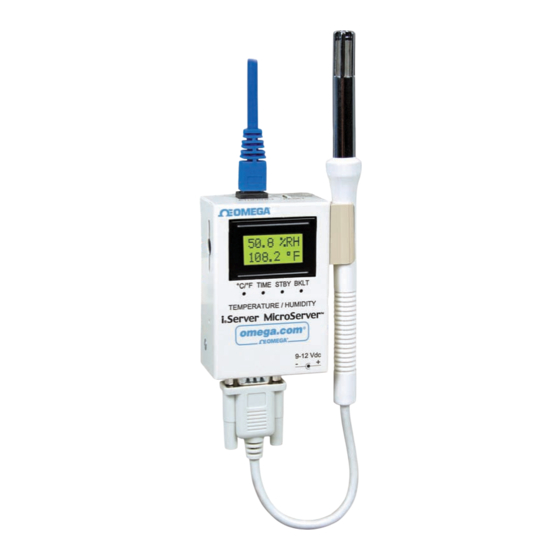
- Page 1 User’ s Guide Shop on line at ® omega.com ® e-mail: info@omega.com For Latest Product Manuals omegamanual.info Temperature + Humidity...
- Page 2 It is the policy of OMEGA to comply with all worldwide safety and EMC/EMI regulations that apply. OMEGA is constantly pursuing certification of its products to the European New Approach Directives. OMEGA will add the CE mark to every appropriate device upon certification.
-
Page 3: Table Of Contents
TABLE OF CONTENTS Part 1: Introduction Safety and EMC Considerations ............2 Before You Begin ...................2 Description....................2 Part 2: Hardware Dimensioins ...................4 Wall Mounting ..................5 DIP Switches...................5 Parts of iServer Unit ................6 Disassembly Instruction ...............7 Network Communication Interfaces ............8 2.6.1 10Base-T RJ-45 Pinout .............8 2.6.2 10Base-T Crossover Wiring .............8 Relay Wiring Connections ..............8... - Page 4 4.8.3 Device Setting Setup and Configuration.......40 Part 5: Specifications ....................41 Part 6: Factory Preset Values ..................42 Appendix A Glossary ....................43 Appendix B IP Address ....................44 Appendix C IP Netmask ....................45 Appendix D ASCII Chart ..................46 ASCII Chart Control Codes ..............47 Appendix E iLog Error Messages................48 Part 7: Approvals Information...
- Page 5 NOTES, WARNINGS and CAUTIONS Information that is especially important to note is identified by the following labels: • NOTE • WARNING or CAUTION • IMPORTANT • TIP NOTE: Provides you with information that is important to successfully setup and use the iServer. CAUTION: Tells you about the risk of electrical shock.
-
Page 6: Part 1: Introduction
PART 1 INTRODUCTION 1.1 Safety and EMC Considerations Refer to the CE Approvals Section. EMC Considerations • Whenever EMC is an issue, always use shielded cables. • Never run signal and power wires in the same conduit. • Use twisted-pair wires for signal connections. •... - Page 7 Award-winning Technology. The iServer is simple to install and use. It features award winning technology that requires no special software except a Web browser. The iServer connects to an Ethernet Network with a standard RJ45 connector and sends data in standard TCP/IP packets.
-
Page 8: Part 2 Hardware
PART 2 HARDWARE 2.1 Dimensions 3.2 [82] 2.42 [61.6] TEMPERATURE/HUMIDITY If unit is to be mounted on a flat surface, you may take the bottom rubber feet off the unit. Dimensions are in inches with millimeters in [ ]. 1.44 [36.6] 0.12 [3.0] 0.10... -
Page 9: Wall Mounting
2.2 Wall Mounting Position unit where required. Mark and drill the two #4 screw holes. After bracket is mounted on the wall, align back of unit over the three bracket clips, once engaged, slide downward, the unit will snap in place. 2.42 [61.6] 0.46 [11.7] 1.50 [38.1]... -
Page 10: Parts Of Iserver Unit
2.4 Parts of the iServer Unit iServer iServer Reset Button iServer LEDs RJ45 interface Side or Bottom ACTIVITY NETWORK LINK Wire Entry for DIAGNOSTICS Relay Connector AND STATUS ETHERNET RESET Removable Plug 16 Digit Connector for Relays LCD Display under the Cover Probe Flash Handle... -
Page 11: Disassembly Instruction
2.5 Disassembly Instruction You may need to open the unit for one of the following reasons: • To wire relay connector. (Refer to Figure 2.8) • To connect or replace the battery. • To change S5 jumper. In the absence of AC power, and if S5 is installed, the LCD Backlight and iServer Board will be on and running on the battery power. -
Page 12: Network Communication Interfaces
2.6 Network Communication Interfaces 2.6.1 10Base-T RJ-45 Pinout The 10BASE-T Ethernet network Name Description + Transmit Data (RJ45) system is used in the iServer - Transmit Data for network connectivity. The 10 Mbps + Receive Data twisted-pair Ethernet system operates Not Connected over two pairs of wires. -
Page 13: Flash Memory Format
2.8 Running on Battery Power (continued) while the unit is recording, the battery will take over and recording will continue. If you want to move the unit to a different location, remove the AC adapter; the installed battery will keep the recording alive until the AC adapter is plugged back in. -
Page 14: Part 3: Network Configuration
PART 3 NETWORK CONFIGURATION 3.1 Network Protocols The iServer can be connected to the network using standard TCP/IP protocols. It also supports ARP, HTTP (WEB server), DHCP, DNS and Telnet protocols. 3.2 Ethernet (MAC) Address MAC (Media Access Control) address is your computer's unique hardware number. When you're connected to the LAN from your computer, a correspondence table relates your IP address to your computer's physical (MAC) address. -
Page 15: Dhcp
3.3 DHCP DHCP, Dynamic Host Configuration Protocol enables individual computers or devices to extract their IP configurations from a server (DHCP server). If the DHCP is enabled on your iServer, as soon as the iServer is connected to the network, there is an exchange of information between DHCP server and the iServer. -
Page 16: Default Ip Address
3.5.1 Default IP Address The iServer is shipped with a default IP address set to 192.168.1.200 and Subnet Mask of 255.255.255.0. If you are going to use a Web browser or Telnet program to access the iServer using its default IP address, make sure that the PC from which you’re establishing the connection has an IP address that is in the same range as the iServer’s IP address (192.168.1.x, where x can be any number from 1 to 254. -
Page 17: Part 4: Operations
PART 4 OPERATIONS This iServer can be used and configured in several ways, depending on user’s preference and network setup. It can be configured using a Web browser, like Netscape or Internet Explorer. It can also be configured using NEWPORT’s iConnect Configuration Software. -
Page 18: Iconnect Software
4.1 iConnect Software The iServer may also be assigned an IP Address by using the iConnect software. Download the iConnect software from the website listed in this manual. Install iConnect software on a networked PC. This software is compatible with Windows 95, 98, NT, 2000, and XP. - Page 19 4.1 iConnect Software (continued) To access the iServer for Configuration: Click on the “View Webpage” button, you will access the iServer’s home page, refer to Section 4.3 for details. iSERVER HOME PAGE Read Sensor Chart Access Control Configuration Figure 4.3 Accessing the iServer’s Home Page Menu...
-
Page 20: Setting A New Ip Address Over The Network
4.2 Setting a New IP Address over the Network Besides using the iConnect software, you may use the iServer’s default IP address to access it and assign a new IP address to it. The iServer is shipped with a default IP address of 192.168.1.200 and Subnet Mask of 255.255.255.0. -
Page 21: Setup And Operation Using The Iserver Web Page
4.3 Setup and Operation Using the iServer Web Page • Start your web browser. • From the browser you type http://eisxxxx using the last four-digits from the MAC address label located on the device if DHCP and DNS are used. If a static IP address is used, then simply type http://x.x.x.x, where x.x.x.x is the iServer’s IP address. -
Page 22: Java Runtime Environment 1.4 Setup Instructions
4.3.1 Read Sensor • Click on . In a few seconds the following page (Figure 4.7) will appear Read Sensor with all default values of 100.00. Then the actual readings of Temperature, Humidity and Dewpoint will display. • This page automatically updates the Temperature, Humidity, and Dew Point values. •... -
Page 23: Java Runtime 1.5 (5.0) Setup Instructions
4.3.1.2 Java Runtime Environment 1.5 (5.0) Setup instructions 1. Go to your computer's Control Panel. Open the Java Plug-in 2. Click on "Settings" & "View Applets" in the "General" tab. 3. Select the "Settings" button on the General Tab Un-check the "Enable Caching" box. Then close dialog box to show the General Tab again 4. -
Page 24: Adjustable Chart
4.3.2 Adjustable Chart • Click on , the following page (Figure 4.8) should appear. The Java™ Applet Chart graph displays Temperature and Humidity values, which can be charted across the full span (-40 to 124ºC, and 0 to 100% RH) or within any narrow range (such as 20 to 30ºC). The time-base can display one minute, one hour, one day, one week, one month or one year. -
Page 25: Retrieving Data From Flash
4.3.3 Retrieving Data from Flash To retrieve and graph the data that is stored in the Flash Memory, you have two options: OPTION 1: You can use the iServer’s WEB interface to chart the data stored in the flash memory. Click on the “Chart”... -
Page 26: Access Control
4.3.4 Access Control This section describes the "Access Control" page of the iServers’s Web interface. This page allows the users to set up the network and security parameters of the iServer. At the initial entrance to the “Access Control” page you will be prompted for the LOGIN Password (see Figure 4.6) prior to an ADMINISTRATOR Password. -
Page 27: Configuration
4.3.4 Access Control (continued) Gateway Address: A gateway is a network point that acts as an entrance to another network. A gateway is often associated with a router, which knows where to direct a given packet of data that arrives at the gateway. If the iServer is sending packets to another network node that is not on the same network on which the iServer is connected, a gateway address needs to be given to the iServer. -
Page 28: Configuration (Recording Not Active)
4.3.5 Configuration (continued) CONFIGURATION Address http://192.168.1.50 CONFIGURATION Sensor Name Read Command Remote Format Offset Remote End Char Temperature SRTF T_00.00F 000.0 Humidity H_00.00% 000.0 Dewpoint SRDF D_00.00F 000.0 Click on Sensor No. on left to modify Sensor Parameters. Title: Data_Record_Test Degree Unit: F LCD/PWR: ON 2-MegaBytes Flash Card 22 Kbytes Used Space... - Page 29 C) Flash Card Messages Describes the status of the Flash Card Flash Card Module Malfunctional Flash Card Standby Flash Card Recording Stopped Flash Card Pre-Recorded Flash Card Recording Complete Flash Recording On Flash Card Module Not Initialized Flash Card Corrupt Initialization Recording Initialized Entries Error Low Battery...
- Page 30 4.3.5 Configuration (continued) F) Terminal Server TCP/UDP*: The iServer supports TCP and UDP protocols (default is TCP). If UDP is selected, it can be configured either for Broadcast UDP or Directed UDP. In case of Broadcast UDP, the iServer will transmit the data to every node on the network.
- Page 31 4.3.5 Configuration (continued) G) Remote Access Remote IP Address: iServer can establish a connection to a remote device (e.g. an iLD Remote Display with an Ethernet iServer embedded board) with this IP. Remote Port: (default 2000) the remote port number for the connection. Ports 1000 (used for HTTPget, refer to Section 4.5), 2002, 2003, and 2004 are reserved for internal use.
-
Page 32: Configuration - Recording Settings
4.3.5 Configuration (continued) I) Start Recording - Recording Settings Figure 4.12 Configuration - Recording Settings Type: The selections are: “No Recording”, “Limited”, and “Full Flash”. No Recording: Not used. Limited: You must define the Start Date and Time, and End Date and Time in which you need the recording to be done. -
Page 33: Configuration - Recording Initializing
4.3.5.1 Configuration - Recording Initializing After starting a recording, the Configuration page will look slightly different. Section C will have a new message Recording Initialized, and Section I will show the Recording Settings, along with a “Stop Recording” button. Note that the Clock Time has not yet reached the Start Time. -
Page 34: Configuration - Recording Active
4.3.5.2 Configuration - Recording Active Once the Clock Time has exceeded the Start Time, click on the “Read Settings” button, followed by the “Update” button, to refresh the Configuration page. Section C will have a new message Flash Recording On, and Section I will still show the current Recording Settings. -
Page 35: Configuration - General Notes
4.3.5.3 Configuration - General Notes NOTE 1: While the recording is in progress, the letter “R” of RH, located on the LCD screen blinks continuously. NOTE 2: Downloading data and recording can not be done at the same time. While downloading data, the writing process to the flash memory will be internally disabled while the data is being read from the memory flash. -
Page 36: Sensor Parameter
4.3.6 Sensor Parameters • In the first column of Configuration page (Figure 4.11), click on No. 1 to view and modify the Sensor Parameters page for Temperature. Sensor Parameters http://192.168.1.200 SENSOR PARAMETERS You may type any Device No. 1 ASCII Sensor Name: Temperature characters in the... -
Page 37: Telnet Setup
4.4 Telnet Setup Set the Number of Connections to 1-5 other than 0, using telnet simulation program connect to iServer. In continuous mode, the telnet teminal will receive continuous messages from the iServer. In command mode, the command can be sent to query the iServer and get a response back. -
Page 38: Httpget Using Port 1000
4.5.1 HTTPget using Port 1000 You can setup and read the information from the iServer by using the HTTPget program. The following program can be used to read data from the iServer by using TCP port 1000. The command string is sent to this TCP port, then the response can be read back from the same socket. -
Page 39: Httpget And Arp To Setup Device Ip Address
4.5.1 HTTPget using Port 1000 (continued) *SR_XE2 Include alarm 2 (enable alarm 2 function) *SR_XP1 Close relay 1 for < 200 mSec *SR_XP2 Close relay 2 for < 200 mSec *SR_XH1 Close relay 1 *SR_XH2 Close relay 2 *SR_XL1 Open relay 1 *SR_XHL Open relay 2 \r is the carriage return termination character... -
Page 40: Arp Protocol
4.6 ARP Protocol ARP is the Internet layer protocol responsible for matching or obtaining the MAC (hardware) address that corresponds to a particular IP address. The ARP command allows the user to view the current contents of the ARP cache of the local computer (residing on the same network). -
Page 41: Ilog Software
4.7 iLog Software This is an Excel application software that can log temperature, humidity and dewpoint from the iServer over the local network (Ethernet) or the internet. Download the iLog software from the website listed in this manual. Install iLog software on a networked PC. This software is compatible with Windows 95, 98, NT, 2000, and XP. -
Page 42: Mail Notifier Software
4.8 Mail Notifier Software The Mail Notifier Software can be used only with NEWPORT Electronics instruments. For complete information of how to use the Mail Notifier software, click on the Help menu of the main window. The Mail Notifier software generates email notifications for alarm conditions. Users can be notified automatically of alarm conditions monitored via internet connections throughout the world. -
Page 43: Program Options Setup And Configuration
4.8.2 Program Options Setup and Configuration Complete program setup requires: • Entering a recipient for the email • Specifying connection details to MAPI services. • Defining alarms for devices, and selecting how and when the email will be active. Options Send To Email Setup Content Startup General Mail Server... -
Page 44: Device Setting Setup And Configuration
4.8.3 Device Setting and Configuration Device setup requires: • Server IP Address: for iSE device (for example 192.168.1.200). • Socket Number: (1000 or 2000 depending on iServer settings). • Bus Address/Device ID: interface address (1 to 199). Enter "0" for RS232 interface or for iServer. - Page 45 Sensor: Digital 4-wire (DB-9) PART 5 SPECIFICATIONS Supported Protocols: SENSOR SPECIFICATIONS TCP/IP, UDP/IP, ARP, ICMP, DHCP, DNS, Relative Humidity (RH) HTTP, and Telnet Accuracy/Range: ±2% for 10 to 90% LED Indicators: Network Activity, Network ±3% for 0 to 10% and 90 to 100% Link, Diagnostics/Status Hysteresis: ±1% RH LCD Display: 16 digits, 6mm (0.23”)
-
Page 46: Part 6: Factory Preset Values
PART 6 FACTORY PRESET VALUES PRESET PARAMETERS FACTORY DEFAULTS Network Interface: IP Address 192.168.1.200 Gateway Address 0.0.0.0 Subnet Mask 255.255.255.0 Device Host Name eis and Last 4 digits from the MAC address Login Password 12345678 Admin Password 00000000 DHCP Disabled Flow Control None End Character... -
Page 47: Appendix A Glossary
APPENDIX A GLOSSARY User of this manual should be familiar with following definitions: ARP (Address Resolution Protocol) is a protocol for mapping an Internet Protocol address (IP address) to a physical machine address that is recognized in the local network. For example, the IP address in use today is an address that is 32-bits long. In an Ethernet local area network, however, addresses for attached devices are 48-bits long. -
Page 48: Appendix Bip Address
Appendix B IP Address An IP address is a unique 32-bit address assigned to a computer and includes: • A network ID number identifying a network. • A host ID number identifying a computer on the network. All IP addresses have been divided into three smaller groups (classes) A, B and C •... -
Page 49: Appendix Cip Netmask
Appendix C IP Netmask IP Netmask or Subnet Mask is a 32-bit pattern of ones and zeros used to determine network portion of an IP address from the host portion of the IP address. Subnet mask is a network ID that is created by borrowing bits from host portion of IP address and using them as part of a network ID. -
Page 50: Appendix Dascii Chart
Appendix D ASCII Chart ASCII Binary ASCII Binary Char No Parity Char No parity 00000000 01000000 00000001 01000000 00000010 01000010 00000011 01000011 00000100 01000100 00000101 01000101 00000110 01000110 00000111 01000111 00001000 01001000 00001001 01001001 00001010 01001010 00001011 01001011 00001100 01001100 00001101 01001101 00001110... -
Page 51: Ascii Chart Control Codes
Appendix D ASCII Chart Continuation 00101111 01101111 00110000 01110000 00110001 01110001 00110010 01110010 00110011 01110011 00110100 01110100 00110101 01110101 00110110 01110110 00110111 01110111 00111000 01111000 00111001 01111001 00111010 01111010 00111011 01111011 < 00111100 01111100 00111101 01111101 > 00111110 01111110 00111111 01111111 ASCII Control Codes ASCII Dec Hex Ctrl Key... -
Page 52: Appendix E Ilog Error Messages
Appendix E iLog Error Messages Error # Description Note -8003 User stopped logging readings. -10005 Failed to find the iServer. Ethernet cable is disconnected, iServer is powered off, connections across the firewall require longer “connection to socket time out” setting. -10006 Windows socket was closed. -
Page 53: Part 7: Approvals Information 7.1 Electromagnetic Compatibility (Emc)
PART 7 APPROVALS INFORMATION 7.1 CE APPROVAL This product conforms to the EMC directive 89/336/EEC amended by 93/68/EEC, and with the European Low Voltage Directive 72/23/EEC. Electrical Safety EN61010-1:2001 Safety requirements for electrical equipment for measurement, control and laboratory. Basic Insulation Pollution Degree 2 Dielectric withstand Test per 1 min •... - Page 54 Specifically this instrument is accurate to within: VALUE SPECIFICATIONS 33% RH ± 2% 75% RH ± 2% @ 25 °C ± 0.5°C One Omega Drive, P.O. Box 4047 • Stamford CT 06907-0047 • U.S.A. TEL: (203) 359-1660 • FAX: (203) 359-7700 www.omega.com • e-mail: info@omega.com...
- Page 55 WARRANTY/DISCLAIMER OMEGA ENGINEERING, INC. warrants this unit to be free of defects in materials and workmanship for a period of one (1) year from the date of purchase. In addition to OMEGA’s standard warranty period, OMEGA Engineering will extend the warranty period for one (1) additional year if the warranty card enclosed with each instrument is returned to OMEGA.
- Page 56 Where Do I Find Everything I Need for Process Measurement and Control? OMEGA…Of Course! Shop on line at omega.com TEMPERATURE Thermocouple, RTD & Thermistor Probes, Connectors, Panels & Assemblies Wire: Thermocouple, RTD & Thermistor Calibrators & Ice Point References Recorders, Controllers & Process Monitors...
Need help?
Do you have a question about the I.Server MicroServer I.THX-M and is the answer not in the manual?
Questions and answers