Table of Contents
Advertisement
Quick Links
Chart
Address
http://192.168.1.200
Readings
Chart
Recording: ON
High 150.0 / Low 78.0
Max. 130.1 / Min. 95.9
108.2 F
Temperature
200
20.0
C/Div
0
Thu Sep 16 08:00:00 PDT 2009
Data Source:
Live
X-axis:
Alarm Relay Set Points:
Bold
Y-axis (left): Temperature
Y-axis (right):
Help[?]
nvironmental Surveillance over the Internet
Web Link
Setup
High 78.0 / Low 25.0
Max. 69.9 / Min. 30.1
50.8 %
1 Hour/Div
Thu Sep 17 12:05:07 PDT 2009
1 Day
Style:
Bold
Humidity
Style:
Bold
Temperature + Humidity
Humidity
100
10.0
%/Div
0
Save Chart
Print Chart
User' s uide
hop on line at
e-mail: info@omega.com
For Latest Product Manuals
omegamanual.info
®
®
omega.com
Advertisement
Table of Contents

Related Manuals for Omega iSD-TH


Summary of Contents for Omega iSD-TH
- Page 1 High 150.0 / Low 78.0 High 78.0 / Low 25.0 Max. 130.1 / Min. 95.9 Max. 69.9 / Min. 30.1 108.2 F 50.8 % Temperature Humidity e-mail: info@omega.com For Latest Product Manuals omegamanual.info 20.0 10.0 C/Div %/Div Thu Sep 16 08:00:00 PDT 2009...
- Page 2 It is the policy of OMEGA to comply with all worldwide safety and EMC/EMI regulations that apply. OMEGA is constantly pursuing certification of its products to the European New Approach Directives. OMEGA will add the CE mark to every appropriate device upon certification.
-
Page 3: Table Of Contents
TABLe oF coNTeNTS Part 1: INTRODUCTION 1.1 Safety and EMC Considerations ..............2 1.2 Before You Begin .....................2 1.3 Description .......................2 Part 2: HARDWARE 2.1 Dimensions .....................4 2.2 Wall Mounting ....................5 2.3 Parts of the iServer Unit ................6 2.4 Disassembly Instruction................7 2.4.1 Battery Installation .................8 2.5 Network Communication Interfaces ............8 2.5.1 10/100 BASE-T RJ-45 Pinout ............8 2.5.2 Connecting iServer to PC/Hub/Switch/Router ......8... - Page 4 TABLe oF coNTeNTS (continued) 4.4.5 Security...................34 4.4.6 Recording ..................36 4.4.6.1 Start Recording ..............36 4.4.6.2 Status ..................38 4.4.6.3 Data Retrieval ..............39 4.4.6.4 Format SD Card ..............40 4.4.7 System ....................40 4.4.7.1 Reboot ..................40 4.4.7.2 Defaults ..................41 4.4.7.3 Upgrade..................41 4.4.7.4 Download Configuration............42 4.4.7.5 Upload Configuration..............42 4.4.8 Diagnostics ..................43 4.4.9 Log Out ...................43 4.5 Readings .....................44...
- Page 5 LIST oF FIGUReS (continued) Figure 2.4 Opening the Unit ...................7 Figure 2.5 Battery Installation ..................8 Figure 2.6 RJ45 Pinout ....................8 Figure 2.7 Relay and I/O Contact Connections ............9 Figure 3.1 Labeling ....................10 Figure 4.1 ARP and httpget Commands on a DOS Window........13 Figure 4.2 Connecting Computer Directly to iServer..........14 Figure 4.3 Network Connections .................14 Figure 4.4 Local Area Connection ................14...
- Page 6 LIST oF FIGUReS (continued) Figure G.2 Java 1.5.x.x. Screen Shots ................65 Figure H.1 Java Policy ....................67 Figure H.2 Java Policy ....................68 Figure J.1 RH Accuracy Chart..................69 Figure J.2 Temperature Accuracy Chart ..............69 Figure J.3 Normal Range ....................69 LIST oF TABLeS Table 2.1 Parts of iServer Unit..................6 Table 4.1 iLog Excel Applications................54 Table F-1 iLog Error Messages ..................63...
- Page 7 NoTeS, WARNINGS and cAUTIoNS Information that is especially important to note is identified by the following labels: • NOTE • WARNING or CAUTION • IMPORTANT • TIP NOTE: Provides you with information that is important to successfully setup and use the iServer. CAUTION: Tells you about the risk of electrical shock.
-
Page 8: Part 1: Introduction
PART 1 INTRodUcTIoN 1.1 Safety and EMC Considerations Refer to the CE Approvals Section. EMC Considerations • Whenever EMC is an issue, always use shielded cables. • Never run signal and power wires in the same conduit. • Use twisted-pair wires for signal connections. •... -
Page 9: Figure 1.1 Iserver And Ild Big Display On The Ethernet Network
Email Alarms. The device can trigger an alarm if temperature goes above or below a set point that you determine. Your alarm can be sent by email to a single user or to a group distribution list, including text messages to cell phones and PDA’s. Alarm Relays. -
Page 10: Part 2 Hardware
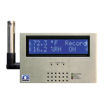
PART 2 HARdWARe 2.1 Dimensions 33.3 2.54 25.4 [1.00] 130.2 [5.13] [1.31] [0.10] C/ F TIME/IP BKLT RECORDING DHCP LINK/ACT 100 BASE-T Dimensions are in mm with inches in [ ]. Figure 2.1 Dimensions If unit is to be mounted on a flat surface, you may take the bottom rubber feet off the unit. -
Page 11: Wall Mounting
2.2 Wall Mounting Position unit where required. Mark and drill the two #4 screw holes. After bracket is mounted on the wall, align back of unit over the three bracket clips, once engaged, slide downward, the unit will snap in place. DRILL 3.17 [0.125] ADDITIONAL MOUNTING OPTION- USE TWO, #4... -
Page 12: Parts Of The Iserver Unit
2.3 Parts of the iServer Unit The 9V battery is the back-up power for the 9Vdc Battery recording function only. (under cover) TOP VIEW 32 Digit LCD Display Warning: The standard SD Flash right angle Memory Card probe is ESD Sensitive Cover Screw... -
Page 13: Disassembly Instruction
2.3 Parts of the iServer Unit (continued) BKLT Button: Push and Hold to display Backlight on LCD when it is running on the back-up battery (backlight is always on while running on the ac adapter). STBY Button: 1) Stops the recording; 2) Press before ejecting Flash Card. NOTE: display will show “Safe to Eject SD”... -
Page 14: Battery Installation
2.4.1 Battery Installation 9 VDC BATTERY INSULATOR COVER TRAY REMOVE BATTERY CLIP INSULATOR COVER AND STORE AGAINST BATTERY WHEN BATTERY IS BEING USED. KEEP INSULATOR COVER ON BATTERY CLIP WHEN BATTERY IS NOT BEING USED Figure 2.5 Battery Installation 2.5 Network Communication Interfaces 2.5.1 10/100 BASE-T RJ-45 Pinout Name Description... -
Page 15: Relay Wiring Connections
2.6 Relay and I/O Wiring Connections To access the Relay and I/O Connectors you must remove the cover, refer to Section 2.4. It is recommended that you ground your unit by connecting a wire to the Ground/Return position of the relay connector or by wrapping a wire around the case’s bottom screw. -
Page 16: Part 3 Network Configuration
PART 3 NeTWoRk coNFIGURATIoN 3.1 Network Protocols The iServer can be connected to an Ethernet network communicating through standard IP protocols including TCP, UDP, SNMP, SMTP, ARP, HTTP (WEB access), DNS, DHCP, ICMP, SNTP, and Telnet. 3.2 Ethernet (MAC) Address MAC (Media Access Control) address is a unique hardware number for Ethernet devices like computers, network switches, print servers, etc. -
Page 17: Dhcp
3.3 DHCP DHCP, Dynamic Host Configuration Protocol, enables computers and network devices to receive their IP configurations from a DHCP server. If DHCP is enabled on your iServer, as soon as the iServer that is connected to the network is powered on, there will be an exchange of information between the iServer and the DHCP server. -
Page 18: Port Number
3.6 Port Number All TCP connections are defined by the IP address and a port number. A port number is an internal address that provides a TCP/IP interface between an application software on a computer and a device on the network or between two devices on the network. There are two default TCP port (socket) numbers assigned to the iServer: 1) Port 2000: Once a TCP connection is made to the iServer using port 2000 or any port number that is configured on the iServer for Local Port (see Network menu,... -
Page 19: Direct Connection (Method 3)
4.1.2 ARP HTTPget Commands (Method 2) (continued) The above IP address of 128.100.101.76 is an example to show how these commands work. To get a valid IP address on your network you need to consult with your IT department. Figure 4.1 shows the screen shot of an actual DOS window with the above commands executed. -
Page 20: Figure 4.2 Connecting Computer Directly To Iserver
4.1.3 Direct Connection (Method 3) (continued) iServer with default IP address of 192.168.1.200 After connecting the iServer to computer, power it on. LINK/ACT LED should be Computer’s SOLID green Ethernet Port (RJ45 RECORDING connection) DHCP LINK / ACT 100 BASE-T Plug in the Ethernet Cable Power Adapter... -
Page 21: Figure 4.5 Changing Tcp/Ip Properties On Your Computer
192.168.1.200 in the “Address” window of your browser and press the Enter key. You will soon be inside the Welcome page (see Figure 4.6) of the iServers WEB server and from there you can access all the menus. iSD-TH Welcome Page Address http://192.168.1.200 Readings... -
Page 22: Figure 4.7 Pinging The Iserver From Ms-Dos Prompt
4.1.3 Direct Connection (Method 3) (continued) To verify a good connection to the iServer, from a DOS prompt on your computer type "ping 192.168.1.200" and press Enter. You should get a reply as shown in Figure 4.7. If you don’t receive a reply it means that you do not have a network connection between your PC and the iServer. -
Page 23: Iconnect Software (Method 4)
4.1.4 iConnect Software (Method 4) The iServer can be assigned an IP Address by using the iConnect software. Download the iConnect software from the website listed on the cover of this manual (software section). Install iConnect software on a networked PC. This software is compatible with Windows 95, 98, NT, 2000, and XP. -
Page 24: Figure 4.9 Accessing The Iserver's Using Iconnect
4.1.4 iConnect Software (Method 4) (continued) To access the iServer for Configuration: Click on the “View Webpage” button, you will access the iServer’s welcome page. To take advantage of the iServer’s full capability use any standard web browser to access the iServer’s web pages as described in Section 4.2. Figure 4.9 Accessing the iServer’s using iConnect... -
Page 25: Access And Configuration Using A Web Browser
4.2 Access and Configuration Using a Web Browser • Start your web browser. • In the URL field, type http://192.168.1.200 (iServer’s default IP address). • The Welcome Page, will be displayed. iSD-TH Welcome Page Address http://192.168.1.200 Readings Chart Setup Web Link Figure 4.10 iServer Welcome Page... -
Page 26: Setup
Once the Administrator password is entered, the Overview page will appear which provides a summary of important parameters within the iServer. All the fields are read-only. Overview Address http://192.168.1.200 Readings Web Link Setup Overview Model iSD-TH Network Firmware Version Configuration DHCP Disabled Management MAC Address 00:03:34:00:b8:70 Security IP Address 192.168.1.200... -
Page 27: Network
4.4.2 Network This menu provides network configurations including IP parameters and Ethernet interface options. Fields are described below. 4.4.2.1 IP Configuration Network Address http://192.168.1.200 Readings Web Link Setup IP Configuration Ethernet Port DHCP Overview Network 00:03:34:00:b8:70 MAC Address Configuration IP Address 192.168.1.200 Management Subnet Mask... - Page 28 4.4.2.1 IP Configuration (continued) Gateway Address – This points to the router that forwards traffic to a destination address outside of the subnet on which the iServer resides. This is the IP address of the router which functions as a gateway. When DHCP is enabled this field will be dimmed. The iServer’s default Gateway address is 0.0.0.0.
-
Page 29: Ethernet Port
4.4.2.2 Ethernet Port Ethernet Port Address http://192.168.1.200 Readings Web Link Setup IP Configuration Ethernet Port Overview Auto-Negotiation Network Speed 100 Mbps 10 Mbps Configuration Duplex Full Half Management Security Recording Save Changes Reset System Diagnostics Log Out Figure 4.14 Network: Ethernet Configuration Auto-Negotiation –... -
Page 30: Figure 4.15 Configuration Menu: Date And Time
4.4.3.1 Data and Time (continued) Date and Time Address http://192.168.1.200 Readings Web Link Setup Date and Time Server Sensors Contact Closures Alarm Relays Overview Date and Time Network Current Date 2099/01/01 (yyyy/mm/dd) Configuration Current Time 00:00:00 Management Change Date and Time Security Recording Time Server... -
Page 31: Server
4.4.3.2 Server Server Address http://192.168.1.200 Readings Web Link Setup Date and Time Server Sensors Contact Closures Alarm Relays Server Overview Network Server Type Command Configuration Interval secs Management Time Stamp Security Disconnect After Data Sent Recording System Diagnostics Save Changes Reset Log Out Figure 4.16 Configuration Menu: Server... -
Page 32: Sensors
4.4.3.3 Sensors This page is where the Sensor Parameters are defined. Reading 1 is for Temperature, Reading 2 is for Humidity, and Reading 3 is for Dewpoint. Sensors Address http://192.168.1.200 Readings Web Link Setup Date and Time Server Sensors Contact Closures Alarm Relays Reading 1 Overview... - Page 33 4.4.3.3 Sensors (continued) End Character – The iServer can attach a character (in Hex) to the end of temperature data packet. This will apply to either Continuous or Command mode. If 00 is entered there will be no character attached. The default is 0D (Hex representation of <CR>). Data Format –...
-
Page 34: Contact Closures
4.4.3.4 Contact Closure Contact Closures Address http://192.168.1.200 Readings Web Link Setup Date and Time Server Sensors Contact Closures Alarm Relays Overview Contacts Contact 2 Contact 1 Disable Disable Network Configuration Description Description Contact In1 Contact In2 Management End Character 0x End Character 0x Security Display... -
Page 35: Alarm Relays
4.4.3.4 Contact Closure (continued) End Character – This means that the iServer will send a character (in Hex) after sending the state of the Output in Continuous or Command mode. Default is 0D (Hex representation of <CR>). Type – The options are Unlatch and Latch. Default is Unlatch. If it’s set to Unlatch, once the Contact is back to NORMAL the Output will automatically change to its original state. - Page 36 4.4.3.5 Alarm Relays (continued) Description – This is a text field for naming the device connected to the relay or it could be the location where the device is installed. This field can take up to 16 alphanumeric characters. This name will be displayed anywhere on the web pages associated with alarm relays;...
-
Page 37: Management
4.4.4 Management This page provides the iServer’s email, SNMP and alarm settings. SNMP (Simple Network Management Protocol) is the protocol used by network management systems to communicate with network devices that respond to SNMP connections for the purpose of problem detections and corrections. If SNMP and/or SMTP features are desired, please make sure iServer’s network setting as well as SNMP trap server and SMTP mail server are setup properly. -
Page 38: Smtp Simple Mail Transfer Protocol
4.4.4.1 Setup (continued) Simple Mail Transfer Protocol SMTP Server – This field specifies the IP Address of the SMTP server. You must have an email server (SMTP server) on your network in order to receive emails generated by the iServer. iServer does not support SMTP server authentication. -
Page 39: Alarms
4.4.4.2 Alarms Alarms Address http://192.168.1.200 Readings Web Link Setup Setup Alarms Overview Events Email SNMP Trap Network Temperature Low Low 0.0 High 0.0 Configuration High Humidity Management High Dewpoint Security Power Reset Recording System Probe Disconnected Diagnostics Recording Stopped Log Out SD Card 10% Memory Left Low Battery Relay 1 Activated... -
Page 40: Security
4.4.4.2 Alarms (continued) Recording Stopped – If the iServer is recording, once the recording is stopped (no matter what the cause was) an email or/and a trap will be sent. SD Card 10% Memory Left – An alarm will be triggered if 10% or less memory left on the flash card. - Page 41 4.4.5 Security (continued) Login Password – To access Readings, Chart, and Web Link menus this password is required. The password length can be up to 16 alphanumeric case-sensitive characters. To change the password click on Change. Empty box means no password is required. The default Login Password is 12345678. Administrator Password –...
-
Page 42: Recording
4.4.6 Recording This section includes all the parameters and settings for data recording, SD flash card and recording status, data retrieval, and formatting the SD card. Fields are described below. 4.4.6.1 Start Recording Start Recording Address http://192.168.1.200 Readings Web Link Setup Start Recording Status Data Retrieval... - Page 43 4.4.6.1 Start Recording (continued) Category – The options are Continuous and Scheduled. In Continuous recording Start Date and Start Time fields are required. If there is not an End Date and End Time, the recording will continue non-stop. In Scheduled recording, any of the days can be selected and the recording will take place only on those days.
-
Page 44: Status
4.4.6.2 Status This page describes the Recording and SD flash card status. All the fields on this page are read-only. Status Address http://192.168.1.200 Readings Web Link Setup Start Recording Status Data Retrieval Format SD Card Overview Current Date: 2099/01/01 Current Time: 00:00:00 Network Recording Status... -
Page 45: Data Retrieval
4.4.6.3 Data Retrieval This page can be used to retrieve the recorded data from the SD flash card and save it into an ASCII file. Using the Retrieve EndDate field select the date (year, month, and day) that is the end date for the retrieved data. -
Page 46: Format Sd Card
4.4.6.4 Format SD Card Clicking on Format SD Card button will start formatting the flash card inside the iServer. Formatting the SD card will erase all data on the card. Allow up to 2 minutes for format to be completed which then it will display "SD Card Formatted". Format SD Card Address http://192.168.1.200... -
Page 47: Defaults
Readings Web Link Setup Reboot Defaults Upgrade Download Configuration Upload Configuration Overview Network Filename: iSD-TH*.bin Configuration Browse... Management Security Upgrade Recording Please make sure no other clients are connected to the device. System Consult manual for complete instructions. Diagnostics Log Out Figure 4.29 System: Upgrade... -
Page 48: Download Configuration
4.4.7.3 Upgrade (continued) After you have successfully upgraded your device, you can verify the firmware version number on the “Overview” page (see Section 4.4.1). It’s recommended to set the iServer to default settings after the firmware is upgraded. See above Section 4.4.7.2 on how to set the iServer to default settings. Applying default settings will change the iServer’s settings to factory defaults. -
Page 49: Upload Configuration
4.4.7.5 Upload Configuration Upload Configuration Address http://192.168.1.200 Readings Web Link Setup Reboot Defaults Upgrade Download Configuration Upload Configuration Overview Network Configuration Browse... Management Security Upload Configuration File *.cfg Recording System Please make sure no other clients are connected to the device. Diagnostics Consult manual for complete instructions. -
Page 50: Readings
4.5 Readings This page displays temperature, humidity, dew point, and the status of the alarm relays and recording. It can be displayed either as an HTML page or a Java applet. 4.5.1 HTML Readings Address http://192.168.1.200 Readings Web Link Setup HTML Java Temperature... -
Page 51: Java
4.5.2 Java If Java option is chosen installation of Java Runtime is required (refer to Appendix G). Readings Address http://192.168.1.200 Readings Web Link Setup HTML Java Temperature 23.0 C Humidity 47.3% Dewpoint 11.0 C Contact1 NORMAL Contact2 ACTIVE Output ACTIVE LOW Recording Auto Update Seconds... -
Page 52: Chart
4.6 Chart This page charts the temperature, humidity, and dew point in real-time across the full span (-40 to 124ºC, and 0 to 100% RH) or within any narrow range (such as 20 to 30ºC). The time-base can display one minute, one hour, one day, one week, one month or one year. Chart Address http://192.168.1.200... -
Page 53: Web Link
4.6 Chart (continued) Data Source – The options are Live and Recorded. If Live is selected the real-time data will be charted for the time indicated on the X-axis. If Recorded is selected the stored data on the SD card will be charted for the time indicated on the X-axis. -
Page 54: Telnet Setup
4.8 Telnet Setup With a telnet program, you can connect to the iServer using its IP address and TCP Port 2000. In Continuous mode (refer to Configuration:Sensors page Section 4.4.3.2), the telnet session will receive continuous data (temperature 1, temperature 2, and differential) from the iServer. -
Page 55: Httpget Program
4.8.1 Telnet Connection (continued) 1.0.1 Administrator Password?00000000 iSD-TH> iSD-TH>Configuration Commands: Administrator Password?00000000 iSD-TH> iSD-TH>p Model: iSD-TH Firmware Ver: 1.0.1 DP: Disabled (0) MC: 00:03:34:00:B9:B6 IP: 192.168.1.200 SM: 255.255.255.0 GW: 0.0.0.0 LP: 12345678 SP: 00000000 TC: Enabled (1) WS: Enabled (1) SR: Enabled (1) iSD-TH>... -
Page 56: Httpget Using Port 2000
4.9.1 HTTPget using Port 2000 You can setup and read the information from the iServer by using the HTTPget program. The following program can be used to read data from the iServer by using TCP port 2000. The command string is sent to this TCP port, then the response can be read back from the same socket. -
Page 57: Flash Card Reader
4.9.1 HTTPget using Port 2000 (continued) *SR_XC1 Reset relay 1 latch condition *SR_XC2 Reset relay 2 latch condition *SR_XE1 Re-enable alarm condition check for relay 1 (must be executed after *SR_XD1) *SR_XE2 Re-enable alarm condition check for relay 2 (must be executed after *SR_XD2) *SR_XP1 Close relay 1 for <... -
Page 58: Opening .Txt Data Files
4.10 Flash Card Reader (continued) File Edit View Favorites Tools Help Name Size Type Date Modified 2010 File Folder 4/01/2010 8:08AM Events File Folder 4/01/2010 8:08AM S20100401.txt 15,598KB Text Document 5/02/2010 1:08PM E:\2010 File Edit View Favorites Tools Help Name Size Type Date Modified... -
Page 59: Ilog Software
4.11 iLog Software This is an Excel application software that can log temperature, humidity and dewpoint from the iServer over the local network (Ethernet) or the internet. Download the iLog software from the website listed on the cover of this manual (software section). -
Page 60: Table 4.1 Ilog Excel Applications
3 column iTHX-M, iTHX-SD 3 column iTHX-W Dual Probe 1st probe / 3 column 6 column iSE-TC, iSD-TC 3 column 5 column iSE-TH, iSD-TH 3 column 5 column iBTHX-W, iBTHX-D 3 column 4 column iBTX-W/-D, iBTX-M, iBTX-SD 2 column iPTX-W... -
Page 61: Part 5 Specifications
PART 5 SPecIFIcATIoNS SeNSoR SPecIFIcATIoNS Relative Humidity (RH) Accuracy/Range: ±2% for 10 to 90%; ±3% for 5 to 10% and 90 to 95% ±4% for 0 to 5% and 95 to 100% Refer to chart in Appendix J Hysteresis: ±1% RH Non-linearity: ±3% Response Time:... - Page 62 iSeRVeR SPecIFIcATIoNS Interfaces Auto MDI/MDIX Ethernet (RJ45): Fixed or auto-negotiating 10/100Base-T; SNTP Supported Protocols: TCP, UDP, SNMP, SMTP, , ARP, ICMP, DNS, DHCP, HTTP, and Telnet LED Indicators: 100 BASE-T, Network Link and Activity, DHCP, Recording LCD Display: 32 digits, 4.8 x 9.7mm (0.19 x 0.38”) Memory Data Flash Card: 2 GB SD Flash Card for 8 months of data storage at 1 second recording intervals, or 7 years at 10 seconds...
-
Page 63: Appendix Aglossary
APPeNdIX A GLoSSARY User of this manual should be familiar with following definitions: ARP (Address Resolution Protocol) is a protocol for mapping an Internet Protocol address (IP address) to a physical machine address that is recognized in the local network. For example, the IP address in use today is an address that is 32-bits long. - Page 64 Appendix B IP Address An IP address is a unique 32-bit address assigned to a computer and includes: • A network ID number identifying a network. • A host ID number identifying a computer on the network. All IP addresses have been divided into three smaller groups (classes) A, B and C •...
-
Page 65: Appendix C Arp Commands
Appendix c ARP commands ARP is the Internet layer protocol responsible for matching or obtaining the MAC (hardware) address that corresponds to a particular IP address. The ARP command allows the user to view the current contents of the ARP cache of the local computer (residing on the same network). -
Page 66: Appendix D Ip Netmask
Appendix d IP Netmask IP Netmask or Subnet Mask is a 32-bit pattern of ones and zeros used to determine network portion of an IP address from the host portion of the IP address. Subnet mask is a network ID that is created by borrowing bits from host portion of IP address and using them as part of a network ID. -
Page 67: Appendix E Ascii Chart
Appendix e AScII chart ASCII Binary ASCII Binary Char No Parity Char No parity 00000000 01000000 00000001 01000000 00000010 01000010 00000011 01000011 00000100 01000100 00000101 01000101 00000110 01000110 00000111 01000111 00001000 01001000 00001001 01001001 00001010 01001010 00001011 01001011 00001100 01001100 00001101 01001101 00001110... -
Page 68: Appendix E Ascii Control Codes
Appendix e AScII chart continuation 00101111 01101111 00110000 01110000 00110001 01110001 00110010 01110010 00110011 01110011 00110100 01110100 00110101 01110101 00110110 01110110 00110111 01110111 00111000 01111000 00111001 01111001 00111010 01111010 00111011 01111011 < 00111100 01111100 00111101 01111101 > 00111110 01111110 00111111 01111111 AScII control codes ASCII Dec Hex Ctrl Key... -
Page 69: Appendix F Ilog Error Messages
Appendix F iLog error messages Table F-1 iLog Error Messages Error # Description Note -8003 User stopped logging readings. -10005 Failed to find the iServer. Ethernet cable is disconnected, iServer is powered off, connections across the firewall require longer “connection to socket time out” setting. -
Page 70: Appendix G Java Runtime Environment Setup
Appendix G Java Runtime environment Setup If your computer does not have Java installed, please download from http://java.sun.com. You can change the Java setting by clicking its icon in Control Panel. To load the applet, you have to enable the web browser and disable cache. G.1 Java Runtime Environment 1.4 Setup instructions 1. -
Page 71: Figure G.2 Java 1.5.X.x. Screen Shots
G.2 Java Runtime Environment 1.5 (5.0) Setup instructions 1. Go to your computer's Control Panel. Open the Java Plug-in 2. Click on "Settings" & "View Applets" in the "General" tab. 3. Select the "Settings" button on the General Tab Un-check the "Enable Caching" box. Then close dialog box to show the General Tab again 4. - Page 72 G.3 Browser Proxy Selection Accessing iServer within your internal network • Usually when the computer and iServers are on an internal network, you will not use Proxy server access. • You should un-check the "Use Browser Settings" option on the "Proxy" tab. Accessing iServers units using the internet •...
-
Page 73: Appendix H Java Policy
Appendix H Java Policy To activate data retrieval and to save charts from the Java applets, it is necessary to create a Java Policy file and copy it onto a folder. Open a Notepad file and using the IP address of the iServer type the following: grant codeBase "http://192.168.1.200/"... -
Page 74: Figure H.2 Java Policy
Java Policy (continued) 5) Change Java Applet’s Runtime Parameters found on the following path: Control Panel --> Java --> Java Control Panel --> Java Tab --> View Inside the box under the Java Runtime Parameters type the following: -Djava.security.policy=C:\0_JAVAPOLICY\java_policy.txt If you have multiple Java Runtime Versions listed, add this line to the version that you are using;... -
Page 75: Appendix J Sensor Information
Appendix J Sensor Information J.1 Accuracy Figure J.1 Figure J.2 RH Accuracy Chart Temperature Accuracy Chart Accuracies are tested at Manufacture’s Outgoing Quality Control at 25°C (77°F) and 3.3V. Values exclude hysteresis and non-linearity, and is only applicable to noncondensing environments. - Page 76 Appendix J Sensor Information (continued) J.4 Reconditioning Procedure As stated above extreme conditions or exposure to solvent vapors may offset the sensor. The following reconditioning procedure may bring the sensor back to calibration state: Baking: 100 – 105°C at < 5%RH for 10h Re-Hydration: 20 –...
-
Page 77: Appendix K Snmp
Object Identifier Object Description Access Default (OID) .1.3.6.1.2.1.1.1 sysDescr The name and version Read-only iSD-TH/ X.XX identification of the product X.XX is the firmware version .1.3.6.1.2.1.1.2 sysObjectID The authoritative identification Read-only .1.3.6.1.4.1.34089.X.X of the network management X.X is the product... - Page 78 PART 6 APPRoVALS INFoRmATIoN 6.1 CE APPROVAL This product conforms to the EMC directive 89/336/EEC amended by 93/68/EEC, and with the European Low Voltage Directive 72/23/EEC. Electrical Safety EN61010-1:2001 Safety requirements for electrical equipment for measurement, control and laboratory. Basic Insulation Pollution Degree 2 Dielectric withstand Test per 1 min •...
- Page 79 WARRANTY/dIScLAImeR OMEGA ENGINEERING, INC. warrants this unit to be free of defects in materials and workmanship for a period of one (1) year from the date of purchase. In addition to OMEGA’s standard warranty period, OMEGA Engineering will extend the warranty period for one (1) additional year if the warranty card enclosed with each instrument is returned to OMEGA.
- Page 80 Where do I Find everything I Need for Process measurement and control? omeGA…of course! hop on line at omega.com TemPeRATURe R Thermocouple, RTD & Thermistor Probes, Connectors, Panels & Assemblies R Wire: Thermocouple, RTD & Thermistor R Calibrators & Ice Point References R Recorders, Controllers &...
Need help?
Do you have a question about the iSD-TH and is the answer not in the manual?
Questions and answers