
Related Manuals for Omega DPF20 Series


Summary of Contents for Omega DPF20 Series
- Page 1 User’s Guide Shop online at omega.com e-mail: info@omega.com For latest product manuals: www.omegamanual.info DPF20 Series Panel Meter for Frequency, Rate, Total or Period Counter ⁄ 6-Digit, DIN Panel Mount...
- Page 2 Fax: (203) 359-7700 e-mail: info@omega.com For Other Locations Visit omega.com/worldwide The information contained in this document is believed to be correct, but OMEGA accepts no liability for any errors it contains, and reserves the right to alter specifications without notice.
- Page 3 Department will issue an Authorized Return (AR) number immediately upon phone or written request. Upon examination by OMEGA, if the unit is found to be defective, it will be repaired or replaced at no charge. OMEGA’s WARRANTY does not apply to defects resulting from any action of the purchaser, including but not limited to mishandling, improper interfacing, operation outside of design limits, improper repair, or unauthorized modification.
-
Page 4: Table Of Contents
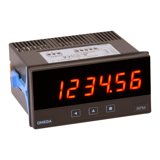
DPF20 Frequency, rate, total or period counter Instruction Manual 1. Panel meter DPF20 Counter, ratemeter and periodmeter, 96 x 48 mm (1/8 DIN) Panel meter 96 x 48 mm (1/8 DIN) and 6 digits with 14 mm digit height, Front protection IP65. Connections by plug-in screw terminals. For in- configurable with 5 impulse counter modes (see section 1.2), 2 rate- dustrial applications. -
Page 5: How To Order
DPF20 Frequency, rate, total or period counter Instruction Manual 1.1 How to order Model Power Option 1 Option 2 Option 3 Others DPF20 -NBT (85-265 Vac/dc) (1 relay) (no buttons) (11/60 Vdc, (analog output) (green led) 24 Vac, 48 Vac) -RTU (Modbus RTU) (RS-485) (RS-232) (1 transistor) -SSR (1 SSR drive) (empty) -
Page 6: Front View
DPF20 Frequency, rate, total or period counter Instruction Manual 1.6 Front view 1.9 Rear view Option 3 Option 1 Option 2 Alarms Logo Units Signal Power Button ‘UP’ Button ‘SQ’ Button ‘LE’ (see section 1.10) (see section 1.7) Front reset ‘Fast access‘ ‘Configuration menu’ (see section 1.19.14) (see section 1.19.12) (see section 1.19) -
Page 7: Technical Specifications
DPF20 Frequency, rate, total or period counter Instruction Manual 1.11 Technical specifications Digits number of digits Counter Mode Frequency Section 7 segments led ‘FAST’ mode active max. 250 KHz 1.19.2 color red or green Counter digit height 14 mm normal mode max. 9 KHz 1.19.2 Reading Counter + inhibition... -
Page 8: Function 'Trigger Sense
DPF20 Frequency, rate, total or period counter Instruction Manual 1.13 Function ‘Trigger Sense’ The trigger level is automatically configured when selecting a sensor from the ‘Sensor / Configuration’ (‘SnSr’ / ‘Auto’) menu list. The trig- ger level can be also manually modified from the ‘SnSr’ / ‘TrIG’ menu entry. -
Page 9: How To Operate The Menus
DPF20 Frequency, rate, total or period counter Instruction Manual 1.17 How to operate the menus The instrument has two menus accessible to the user : Example of operation inside the ‘configuration menu’. ‘Configuration menu’ (key SQ) (<) 1. The SQ (<) key enters into the ‘Fast access’... -
Page 10: Configuration Menu
DPF20 Frequency, rate, total or period counter Instruction Manual 1.19 Configuration menu Press ‘SQ’ (<) for 1 second to access the ‘configuration menu’. 1.19.1 Initial set-up For a description on how to operate inside the menus see section 1.17 . For a full vision of the ‘configuration menu’ structure see To configure the initial set up of the instrument, select the function 1.20 section... -
Page 11: Configuration For 'Cnq.2
DPF20 Frequency, rate, total or period counter Instruction Manual 1.19 Configuration menu (cont.) 1.19.3 Configuration for ‘cnq.2’ Multiplier Configuration menu for mode ‘counter quadrature’ (‘cnq.2’). To- 1 to 999999 Multiplier tal impulses received are multiplied by the value of the ‘multiplier’ Conf. -
Page 12: Configuration For 'Cnd.5
DPF20 Frequency, rate, total or period counter Instruction Manual 1.19 Configuration menu (cont.) 1.19.6 Configuration for ‘cnd.5’ Multiplier Configuration menu for mode ‘counter differential’ (‘cnd.5’). To- 1 to 999999 Configuration Multiplier tal impulses received are multiplied by the value of the ‘multiplier’ counter (‘MuLt’) register and divided by the ‘divider’... -
Page 13: Configuration For 'Prd.8
DPF20 Frequency, rate, total or period counter Instruction Manual 1.19 Configuration menu (cont.) • for slow frequencies activate the ‘SLoW’ parameter configuring the ‘tIME’ parameter between 1 and 1000 seconds. Configure the ‘nuMb’ Max. waiting time parameter between 1 and 32 impulses. See section 1.15 for more in- ‘SLOW’... - Page 14 DPF20 Frequency, rate, total or period counter Instruction Manual 1.19 Configuration menu (cont.) • ‘Pulls on channel A’ (‘PuL.A’) - activates pull resistors at chan- No pull resistor nel A. Select ‘P.uP’ to activate pull-up resistors (needed for NPN Pulls on channel A sensors).
-
Page 15: Alarms
DPF20 Frequency, rate, total or period counter Instruction Manual 1.19 Configuration menu (cont.) 1.19.11 Alarms Alarms The ‘Alarms’ (‘ALr’) menu configures the independent activation of up to 3 relay outputs (or transistor or SSR drive control), installed with the R1 optional modules (or T1 or SSR) (see section 2.1). For Alarm 1 Active outputs up to 4 and 6 relays, see special modules R2, R4 and R6 at... -
Page 16: Fast Access
DPF20 Frequency, rate, total or period counter Instruction Manual 1.19 Configuration menu (cont.) 1.19.12 Fast access The ‘UP’ (5) key at the front of the instrument gives access to a list of func- Tools tions configurable by the operator. See section 1.17 for an explanation on how to operate the ‘fast access’... -
Page 17: Menus 'Overrange / Underrange
DPF20 Frequency, rate, total or period counter Instruction Manual 1.19 Configuration menu (cont.) 1.19.16 Menus ‘Overrange / underrange’ Flash Counter The ‘Counter overrange’ (‘c.orG’) and ‘Counter underrange’ (‘c.urG’) To zero overrange parameters configure the behavior of the instrument when reading is higher than ‘9999’... -
Page 18: Full Configuration Menu
DPF20 Frequency, rate, total or period counter Instruction Manual 1.20 Full configuration menu Press ‘SQ’ (<) for 1 second to access the ‘Configuration menu’. See 1.19 section for a description of each menu entry. Multiplier Counter 1 to 999999 Multiplier Conf. - Page 19 DPF20 Frequency, rate, total or period counter Instruction Manual 1.20 Full configuration menu (cont.) Max. waiting time Max. waiting time ‘SLOW’ mode ‘SLOW’ mode Number of pulses Number of pulses Filter strength Filter strength Average filter Average filter (0 = disabled) (0 = disabled) Multiplier Mechanical contact...
- Page 20 DPF20 Frequency, rate, total or period counter Instruction Manual 1.20 Full configuration menu (cont.) rising edge Channel A acti- Tools falling edge vation by rising edge Key UP Setpoint 1 Activation for (‘fast access’) reset by falling edge Setpoint 2 Excitation voltage Setpoint 3 Memory of maximum...
-
Page 21: Factory Configuration
DPF20 Frequency, rate, total or period counter Instruction Manual 1.20 Full configuration menu (cont.) 1.21 Factory configuration Function counter (‘cn.1’) With left zeros Decimal point Counter configuration Left zeros Without left zeros Multiplier Divider with Vexc. error control Preset Mode Control Vexc. -
Page 22: To Access The Instrument
DPF20 Frequency, rate, total or period counter Instruction Manual 1.22 To access the instrument To open the housing, use a flat screwdriver to free the fixation clips, if possible, in the following order : D, C, B and A. Remove the front cover. -
Page 23: Precautions On Installation
DPF20 Frequency, rate, total or period counter Instruction Manual 1.24 Precautions on installation 1.25 CE declaration of conformity Products DPF20 Risk of electrical shock. Instrument terminals can be connected The manufacturer declares that the instruments indicated comply with the to dangerous voltage. directives and rules indicated below. -
Page 24: Output And Control Modules
DPF20 Frequency, rate, total or period counter Instruction Manual 2. Output and control modules 2.1 Módules R1, T1 and SSR The R1, T1 and SSR modules provides 1 relay output, 1 transistor out- The menu allows to configure the setpoint, hysteresis, independent put or 1 SSR drive output, to install in DPF20 digital panel meters, up activation and deactivation delays, and a second setpoint to create to a maximum of 3 modules in a single meter. -
Page 25: Module Ao
DPF20 Frequency, rate, total or period counter Instruction Manual 2.2 Module AO Module AO provides 1 analog output configurable as 4/20 mA or provides the excitation for the loop ) or as a passive loop (the loop is 0/10 Vdc, to install in DPF20 digital panel meters. externally powered). -
Page 26: Configuration Menu
DPF20 Frequency, rate, total or period counter Instruction Manual 2.2.1 Configuration menu Configure at menu ‘Mode’ (‘ModE’) the output signal range to Mode 4/20 mA ‘4/20 mA’ (‘mA’) or ‘0/10 Vdc‘ (‘Vdc’). Position for jumpers ‘V’ and Mode ‘M’ must be according to the range selected. Mode 0/10 Vdc At menu ‘Scaling’... -
Page 27: Module Rtu
DPF20 Frequency, rate, total or period counter Instruction Manual 2.3 Module RTU Module RTU provides 1 Modbus RTU communications port, to install Up to a maximum of 3 RTU modules can be installed in a single in- in DPF20 digital panel meters. Enables protocol function ‘4’ (‘Read In- strument, all modules isolated between them and isolated from all put Registers’) to access the instrument registers (reading value, alarm other circuits. -
Page 28: Configuration Menu
DPF20 Frequency, rate, total or period counter Instruction Manual 2.3.2 Configuration menu Configure at menu ‘Configuration’ (‘rtu’), the address value between ‘1’ and ‘247’ at parameter ‘Address’ (‘Addr’), bus speed in kbps at parameter ‘Speed’ (‘bAud’) and data format at parameter ‘Format’ 1 to 247 (‘bItS’). -
Page 29: Description And Example For Modbus Rtu Registers
DPF20 Frequency, rate, total or period counter Instruction Manual 2.3.4 Description and example for Modbus RTU registers Register R0 and R1 (DISPLAY1_L and DISPLAY1_H) Register R9 and R10 (SETPOINT2_L and SETPOINT2_H) Contains the display value of the instrument, codified in two registers Contains the setpoint value of alarm 2, codified in two registers of 16 of 16 bits each. -
Page 30: Module S4
DPF20 Frequency, rate, total or period counter Instruction Manual 2.4 Module S4 Module S4 provides 1 RS-485 ASCII communications port, to install in Protocol configuration is performed from the frontal keypad of the DPF20 digital panel meters. ASCII protocol with ‘master’ - ‘slave’ ar- meter, by setting the parameters at the options configuration menu chitecture. -
Page 31: Configuration Menu
DPF20 Frequency, rate, total or period counter Instruction Manual 2.4.2 Configuration menu At menu ‘Configuration ASCII’ (‘AScI’), configure the instrument at parameter ‘Mode’ (‘ModE’) to work as ‘slave’ or ‘master’, at param- eter ‘Address’ (‘Addr’) set the address value from ‘1’ to ‘31’, set the ‘Slave’... -
Page 32: Frame Types
DPF20 Frequency, rate, total or period counter Instruction Manual 2.4.4 Frame types The ASCII protocol defines the following frames: • Frame ‘error’ (‘ERR’). Id code 38. Response frame to a request data frame. Indicates that an error has occurred. Error code is codified •... -
Page 33: Frame Examples
DPF20 Frequency, rate, total or period counter Instruction Manual 2.4.7 Frame examples Frames ‘RD’ (36) and ‘ANS’ (37) Example - ‘Master’ (address ‘0’) requests the value of register ‘0’ (dis- *Instruments with 4 digits also send reading values formatted with 6 play value) to the ‘Slave’... -
Page 34: Module S2
DPF20 Frequency, rate, total or period counter Instruction Manual 2.5 Module S2 2.6 Modules R2, R4 and R6 Module S2 provides 1 RS-232 ASCII communications port, to install in Modules R2, R4 and R6 provide 2, 4 and 6 relay outputs, to install in DPF20 digital panel meters. -
Page 35: Configuration Menu
DPF20 Frequency, rate, total or period counter Instruction Manual 2.6.1 Configuration menu To configure alarm 1, access the ‘Alarm 1’ (‘ALr1’) menu and config- ure the following parameters : To configure alarms 2, 3, etc, access Alarm 1 Active the corresponding menu entries. •... -
Page 36: How To Open And Close
DPF20 Frequency, rate, total or period counter Instruction Manual 3. How to open and close 3.1 How to open the housing A. Locate the clips Locate the 4 clips (A B C D). Clips are covered by the front filter. Clips can be seen when looking from the rear of the instrument, just below the front filter. -
Page 37: How To Close The Housing
DPF20 Frequency, rate, total or period counter Instruction Manual 3.2 How to close the housing A. Locate the clips Locate the 4 clips (A B C D) at the housing (image A.1) and the 4 matting clips at the filter (image A.2). With the instrument inside the housing, face the front filter against the housing (do not clip yet). - Page 38 DPF20 Frequency, rate, total or period counter Instruction Manual...
- Page 39 DPF20 Frequency, rate, total or period counter Instruction Manual...
- Page 40 Where Do I Find Everything I Need for Process Measurement and Control? OMEGA…Of Course! Shop online at omega.com TEMPERATURE Thermocouple, RTD & Thermistor Probes, Connectors, Panels & Assemblies Wire: Thermocouple, RTD & Thermistor Calibrators & Ice Point References Recorders, Controllers & Process Monitors...
Need help?
Do you have a question about the DPF20 Series and is the answer not in the manual?
Questions and answers