
Subscribe to Our Youtube Channel
Related Manuals for Omega DPG8001


Summary of Contents for Omega DPG8001
- Page 1 User’s Guide Shop online at omega.com e-mail: info@omega.com For latest product manuals: omegamanual.info DPG8001 M-5103/0217 General Purpose Digital Pressure Gauge...
- Page 3 Fax: (203) 359-7700 e-mail: info@omega.com For Other Locations Visit omega.com/worldwide The information contained in this document is believed to be correct, but OMEGA accepts no liability for any errors it contains, and reserves the right to alter specifications without notice.
-
Page 5: Installation
Symptoms of fluid ham- pressure containing parts, or other misuse. mer and surge’s damaging effects: Consult Omega Engineering before installing • Digital Gauge exhibits large zero offset. if there are any questions or concerns. • Digital Gauge pressure display remains 2. -
Page 6: General Information
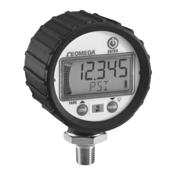
4. GENERAL INFORMATION: Keypad: Power On-Off / Enter Zero / Up Arrow / Tare Tare ZERO Menu Selection / Down / Backlight Arrow M ENU Key presses are short less than 0.5 seconds or long greater than 0.5 seconds ➟ ➟... - Page 7 LCD DISPLAY: LCD functions: 5 numerical digits for pressure display. 20 segment pressure range bar graph – each segment equals 5% of range. Sleep and Backlight Timer symbols. Maximum / Minimum Pressure and Tare icons. 5 character alpha-numeric digit display. 4 segment battery life indicator.
- Page 8 Key presses designated as long (greater than display momentarily disappears and “ZERO” ➟ 0.5 sec.) are indicated by “ ” ICON shows in alpha display, then returns to mea- surement mode. The pressure should now read Turn the Gauge ON/OFF 0.
- Page 9 ➟ displayed in Measurement mode. 1. Press and release to proceed M ENU In Measurement mode, apply desired pressure to programming mode. ➟ ➟ press , to enable the tare function. The ZERO 2. Press , to scroll through pro- display will quickly flash “TARE”, then the grammable menu options.
- Page 10 sure, user must enter the full scale value of the the next digit to the right will begin blinking. desired reading, which can be done as follows. Repeat this procedure for all 5 digits. When ➟ ➟ is pressed and released with 1) In Menu Mode press select ➟...
- Page 11 this is initiated upon powering the unit or since ered ON once the Power key is pressed. the values were cleared. ➟ 1. When in menu mode press ➟ 1. When in menu mode press to scroll until “TIMER” is displayed. to scroll to ‘Max’...
- Page 12 Determines how long the back light will remain Utilized to select the rate at which the displayed ON after any key is pressed in Measurement or pressure value is updated on the screen. Menu Modes (Note: The timer is reset with any This function is used when rapid changes in key being pressed.) pressure cause “flutter”...
- Page 13 Utilized to prevent inadvertent re-zeroing of the Provides the user the ability to field calibrate the instrument. product. Original factory calibration is perma- ➟ nently retained in memory and can be recalled 1. In Menu mode, press until at any time. “ZLOCK”...
- Page 14 Graph: 8. Display flashes “APPLY/ REF/ PSI/ THEN/ PRESS/ ENTER/ TO/ START/ OR/ OTHER/ Provides the user the ability to modify pressure TO/ ABORT”; apply the pressure indicated values dictating the minimum / maximum indi- in numeric display to gauge and press cations over the 20 segment bar graph.
- Page 15 6. To program minimum graph percentage, Reset: the display will indicate 0 0 with the right Returns the product to the factory default val- digit flashing, the bottom most segment ues.Preserves field calibration. Factory calibra- of the bar graph will flash, and the tion can be restored in the “RECAL”...
- Page 16 Changing Batteries: Grip knurled back cover and rotate count- er-clockwise until the ‘unlock’ icon is in align- ment with the arrow – this is on the housing at the base of the pressure connection. Remove cover by pulling straight back and replace AA alkaline batteries accordingly;...
- Page 17 Pressure Range: Dimensions: Proof Pressure: Vac-2000: 200% 69.36mm % of Span 3000-5000: 150% Ø2.73in 7500-25,000: 120% Burst Pressure: Vac-2000: 800% % of Span 3000-5000: 500% 7500-25,000: 300% Environmental Specifications: 50.5mm 1.99in Temperature 67mm 2.64in Storage: Batteries removed: –20°C to 80°C (-4°F to 176°F) 1/4 NPT Male Batteries installed: –20°C to 60°C (-4°F to 140°F)
- Page 19 Service Department will issue an Authorized Return (AR) number immediately upon phone or written request. Upon examination by OMEGA, if the unit is found to be defective, it will be repaired or replaced at no charge. OMEGA’s WARRANTY does not apply to defects resulting from any action of the purchaser, including but not limited to mishandling, improper interfac- ing, operation outside of design limits, improper repair, or unauthorized modification.
- Page 20 Where Do I Find Everything I Need for Process Measurement and Control? OMEGA…Of Course! Shop online at omega.com TEMPERATURE M U Thermocouple, RTD & Thermistor Probes, Connectors, Panels & Assemblies M U Wire: Thermocouple, RTD & Thermistor M U Calibrators & Ice Point References M U Recorders, Controllers &...
Need help?
Do you have a question about the DPG8001 and is the answer not in the manual?
Questions and answers