
Subscribe to Our Youtube Channel
Related Manuals for Omega FMG90 Series


Summary of Contents for Omega FMG90 Series
- Page 1 User’ s Guide Shop online at omega.com e-mail: info@omega.com For latest product manuals: omegamanual.info FMG90 Series Electromagnetic Flow Meter...
-
Page 3: Table Of Contents
Table of contents page 1 About this operating manual..................4 2 Device description....................5 2.1 Intended use....................6 2.1 Exclusion of liability ..................6 3 Safety instructions....................7 4 Construction and function ..................8 5 Installation ....................... 8 5.1Installation instructions ................... 9 5.2 Assembly ....................... -
Page 4: About This Operating Manual
" • Thoroughly read and understand the information in the section (Safety Instructions If you have any problems or questions, please contact: One Omega Dr. Box 4047 Stamford, CT 06907-0047 Tel: (203) 359-1660 e-mail: info@omega.com Hazard signs and other symbols used:... -
Page 5: Device Description
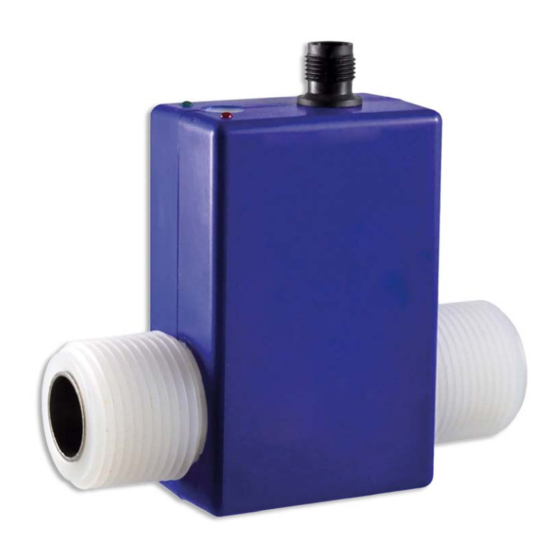
2 Device description The FMG90 series from Omega, is a non-contact flow sensor. The measurement is performed using magnetic induction and works without any moving parts. The FMG90 is used for measuring or metering water and aqueous solutions. The compact design and independence from the intake and discharge sections allows the FMG90 to be used under a variety of conditions. -
Page 6: Intended Use
Intended use The magnetic inductive flow sensor FMG90 must only be used for measuring and metering liquids with a minimum conductivity of 20 μS/cm. WARNING! No safety component! The magnetic inductive flow sensor of the series FMG90 are not safety components in accordance with Directive 2006-42-EC (Machine Directive). -
Page 7: Safety Instructions
In order to guarantee that the device operates safely, the operator must act competently and be conscious of safety issues. Omega provides support for the use of its products either personally or via relevant literature. The customer verifies that our product is fit for purpose based on our technical information. -
Page 8: Construction And Function
Construction and function Construction: The measuring tube with its earthing sleeves and electrodes passes through the sensor housing and forms the external process connection of the FMG90. A magnetic field for the measurement process is generated inside the sensor housing, which also contains the sensor and signal conditioning circuitry. -
Page 9: Installation Instructions
Installation instructions CAUTION! Risk of malfunction due to external magnetic fields! Magnetic fields close to the device can cause malfunctions and should be avoided. Ensure that no external magnetic fields are present at the installation site of the FMG90. • The FMG90 can always be installed anywhere along the pipeline. -
Page 10: Assembly
• If two or more FMG90 devices are used side by side, maintain a separation of at least 2.5 cm between adjacent devices. If adjacent devices are too close together, operation of both devices may be impaired due to mutual interference. 5.2 Assembly The FMG90 is installed directly into the pipeline. -
Page 11: Electrical Connection
6 Electrical connection The electrical connection of the FMG90 is via the 4-pin plug M12x1 at the top. The corresponding connection cables with moulded coupling socket are available in various lengths. CAUTION! Electric current! The electrical connection should only be carried out by a fully qualified electrician. De-energize the electrical system before connecting the FMG90. -
Page 12: Commissioning And Measuring Operation
7 Commissioning and measuring operation Before switching on the FMG90 for the first time, please follow the instructions in the following section. Commissioning Check that the FMG90 has been installed correctly and that all screw connections are sealed. the electrical wiring has been connected properly. the measuring system is vented by flushing. -
Page 13: Disassembly And Disposal
9 Disassembly and disposal CAUTION! Risk of injury! Never remove the device from a plant in operation. Make sure that the plant is shut down professionally. Before disassembly: Prior to disassembly, ensure that the equipment is switched off and is in a safe and de-energised state. the equipment is depressurised and has cooled down. -
Page 14: Technical Data
10 Technical data The technical data of customised versions may differ from the data in these instructions. Please observe the information specified on the type plate. Type FMG 91 FMG 92 FMG 93 FMG 94 FMG 95 FMG 96 Measurement device characteristics Flow range [GPM] 0.066…1.3 0.26…5.3... -
Page 15: Materials Table
10.1 Materials table Component Material Component- wetted Sensor housing Measuring tube PVDF Process connections PVDF O-ring EPDM Electrodes Stainless steel 316L Grounding rings Stainless steel 316L 10.2 Pressure drop FMG 91 / FMG 92 FMG 91 / FMG 92 FMG 93 FMG 93 FMG 96 FMG 96... -
Page 16: Dimensions
10.3 Dimensions FMG 91 - 95 Type 4± 0.02 0.83± 0.01 ½ - 14 NPT Ø 0.31 FMG 91 4± 0.02 0.83± 0.01 ½ - 14 NPT Ø 0.31 FMG 92 4.02± 0.02 0.83± 0.01 ¾ - 14 NPT Ø 0.55 FMG 93 1 –... - Page 18 M-5204/1112...
Need help?
Do you have a question about the FMG90 Series and is the answer not in the manual?
Questions and answers