Crestron Isys TPS-12L Operation Manual
Wall mount touchpanel
Hide thumbs
Also See for Isys TPS-12L:
- Installation manual (68 pages) ,
- Dimension manual (38 pages) ,
- Quick start (2 pages)
Table of Contents
Advertisement
Quick Links
Advertisement
Table of Contents
Troubleshooting

Related Manuals for Crestron Isys TPS-12L


Summary of Contents for Crestron Isys TPS-12L
- Page 1 Crestron Isys TPS-12L/15L/17L ® Wall Mount Touchpanels Operations Guide...
- Page 2 This document was prepared and written by the Technical Documentation department at: Crestron Electronics, Inc. 15 Volvo Drive Rockleigh, NJ 07647 1-888-CRESTRON All brand names, product names and trademarks are the property of their respective owners. ©2005 Crestron Electronics, Inc...
-
Page 3: Table Of Contents
Touchpanel Removal ....................... 29 Recommended Cleaning......................29 Programming Software.....................30 Earliest Version Software Requirements for the PC..............31 Programming with Crestron System Builder ................31 Programming with SIMPL Windows ..................32 Programming with VisionTools Pro-e ..................34 Hard Button Programming ...................... 37 Reserved Join Numbers ...................... -
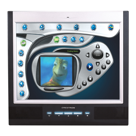
Page 5: Crestron Isys ® Wall Mount Touchpanels: Tps-12L/15L/17L
These touchpanels are QuickMedia™ compatible. The features and specifications (except for screen size and resolution) for all three touchpanels are identical. The TPS-12L/15L17L touchpanels are available with a variety of color bezels (ex. black with silver accent, white with gray accent). - Page 6 TPS-12L/15L/17L TPS-12L/15L/17L Block Diagram Memory The TPS-12L/15L/17L touchpanels feature 128 MB DDR RAM and 32 MB Flash, with a built-in compact flash slot that allows flash memory expansion up to 160 MB. Sound Audio capabilities include 5 Watts per channel biamplified audio speakers that offer built-in volume control, a built-in microphone and built-in WAV sound file capability.
-
Page 7: Specifications
USB port is provided for future applications. The "RS-232 Port for Touch Output" operation transmits touch coordinates to external devices via RS-232 for “Touch-The-PC” and other functions. Specifications The following table provides a summary of specifications for the TPS-12L/15L/17L. TPS-12L/15L/17L Specifications SPECIFICATION DETAILS ®... - Page 8 TPS-15L 300:1 TPS-17L 400:1 Illumination Backlit fluorescent Viewing Angle TPS-12L +/- 70 degrees horizontal, +45/-55 degrees vertical TPS-15L +/- 85 degrees horizontal and vertical TPS-17L +/- 88 degrees horizontal and vertical Enclosure Metal enclosure with molded plastic bezel 32-bit Motorola Coldfire...
-
Page 9: Physical Description
Weight: 12.7 lbs (5.76 kg) Accessories TPMC-CH-IMC interface unit included The latest software versions can be obtained from the Crestron website. Refer to the NOTE following these footnotes. Crestron 2-Series control systems include the AV2 and PRO2. Consult the latest Crestron Product Catalog for a complete list of 2-Series control systems. - Page 10 ® Wall Mount Touchpanels Crestron Isys TPS-12L/15L/17L TPS-15L TPS-17L ¥ Wall Mount Touchpanels: TPS-12L/15L/17L Operations Guide – DOC. 6355...
- Page 11 ® Crestron Isys TPS-12L/15L/17L Wall Mount Touchpanels TPS-12L Physical View – Bottom, Front, and Top TPS-12L Physical View – Side Wall Mount Touchpanels: TPS-12L/15L/17L ¥ 7 Operations Guide – DOC. 6355...
- Page 12 ® Wall Mount Touchpanels Crestron Isys TPS-12L/15L/17L TPS-12L Physical View – Rear ¥ Wall Mount Touchpanels: TPS-12L/15L/17L Operations Guide – DOC. 6355...
- Page 13 ® Crestron Isys TPS-12L/15L/17L Wall Mount Touchpanels TPS-15L Physical View – Top, Front, Bottom TPS-15 Physical View – Side Wall Mount Touchpanels: TPS-12L/15L/17L ¥ 9 Operations Guide – DOC. 6355...
- Page 14 ® Wall Mount Touchpanels Crestron Isys TPS-12L/15L/17L TPS-15 Physical View – Rear ¥ Wall Mount Touchpanels: TPS-12L/15L/17L Operations Guide – DOC. 6355...
- Page 15 ® Crestron Isys TPS-12L/15L/17L Wall Mount Touchpanels TPS-17L Physical Views – Top, Front, Bottom TPS-17L Physical Views – Side Wall Mount Touchpanels: TPS-12L/15L/17L ¥ 11 Operations Guide – DOC. 6355...
- Page 16 TPS-17L Physical Views – Rear Ports and Pushbuttons All connections to the TPS-12L/15L/17L are made through the ports on the rear panel. Refer to the illustrations and descriptions that follow. NOTE: Rear ports are not accessible after the touchpanel is mounted in the wall or in a lectern.
- Page 17 DESCRIPTION Front N/C (Not connected) PC to TPS-12L/15L/17L Cable Specifications (Crestron Cable Number STCP-502PC) One 8-wire RJ-45 connector with two LED indicators (green LED indicates link status, yellow LED indicates Ethernet activity). This connector provides an Ethernet 10baseT /100baseTX, full duplex, TCP/IP, UDP/IP, CIP, DHCP, IEEE 802.3U compliant network connection.
- Page 18 The flash memory slot is accessible on the rear panel of the unit. QM IN (QuickMedia Input) The eight-pin RJ-45 QuickMedia transport port accepts Crestron Certified Wiring carrying audio, video, and microphone signals. The QM input port conforms to the 568B wiring standard.
- Page 19 This eight-pin RJ-45 connection provides connectivity to the CNX-PVID or the TPMC-CH-IMC interface module. This port provides component, composite or S-video balanced input to the touchpanel over Crestron Certified Wiring. Description of the pinouts is shown in the following table.
-
Page 20: Industry Compliance
NOTE: The TPMC-CH-IMC is not for use with QuickMedia. Industry Compliance As of the date of manufacture, the TPS-12L, TPS-15L, and TPS-17L have been tested and found to comply with specifications for CE marking and standards per EMC and Radiocommunications Compliance Labelling. -
Page 21: Setup
Cresnet power usage of the entire chain. If the unit is a home-run from a Crestron system power supply network port, the Cresnet power usage of that unit is the Cresnet power usage of the entire run. The wire gauge and the Cresnet power usage of the run should be used in the following equation to calculate the cable length value on the equation’s left side. -
Page 22: Quickmedia Network Wiring
The aggregate cable length of a signal path originating at a QM transmitter and terminating at the TPS-12L/15L/17L must not exceed 328 feet (100 meters). Video signals may experience a loss of quality over very long lengths of cable. This phenomenon is due to the added resistance and capacitance of longer cable lengths, and is not particular to either Crestron and/or QuickMedia systems. -
Page 23: Configuring The Touchpanel
EEPROM and displays the main page that has been programmed into your system. The remaining buttons on the MAIN MENU open other menus, which are discussed in subsequent paragraphs. MAIN MENU Calibration Menu CALIBRATION MENU Wall Mount Touchpanels: TPS-12L/15L/17L ¥ 19 Operations Guide – DOC. 6355... -
Page 24: Setup Menu
After setup parameters have been selected, select the Return button to return to the MAIN MENU. NOTE: For convenience, the current CRESNET ID setting is displayed in the upper left corner. NOTE: All touchpanel settings are automatically saved in non-volatile memory. SETUP MENU ¥ Wall Mount Touchpanels: TPS-12L/15L/17L Operations Guide – DOC. 6355... - Page 25 ID set in the SIMPL Windows program of the Cresnet system. Matching IDs between touchpanel and SIMPL Windows program is required if data is to be successfully transferred. Net ID for the TPS-12L/15L/17L is factory set to 03. No two devices in the same system can have the same Net ID.
- Page 26 Disable CIP to prohibit any CIP connection. CIP must be enabled for the touchpanel to communicate with other Crestron Ethernet devices. NOTE: TPS-12L/15L/17L do not support a wireless Ethernet connection. Select the Return button located on the INTERFACE MENU to return to the SETUP MENU.
- Page 27 After audio parameters have been set, select the Return button to return to the SETUP MENU. AUDIO MENU Refer to the following table for additional AUDIO MENU setup details. Wall Mount Touchpanels: TPS-12L/15L/17L ¥ 23 Operations Guide – DOC. 6355...
- Page 28 IP Address, Subnet Mask, Default Router, IP Table, etc. The settings can only be viewed from this screen. The enable/disable Ethernet feature is provided on the INTERFACE MENU. Ethernet settings are made through Crestron Toolbox. Refer to page 51 for additional Ethernet setup details.
- Page 29 2. Adjustment applies to the currently selected video source only. 3. QM IN and Video IN are mutually exclusive (i.e., auto-detect for QM IN de-selects auto-detect for Video IN). Wall Mount Touchpanels: TPS-12L/15L/17L ¥ 25 Operations Guide – DOC. 6355...
-
Page 30: Hardware Hookup
Diagnostics Menu The Diagnostics button from the MAIN MENU contains controls for diagnostic tools. The diagnostic tools should only be used under supervision from a Crestron customer service representative during telephone support. The options available from the DIAGNOSTICS MENU are numeric in nature and their interpretation is beyond the scope of this manual. - Page 31 Crestron Isys TPS-12L/15L/17L Wall Mount Touchpanels NOTE: Crestron recommends an independent power supply for the touchpanel. TPS-12L/15L/17L Hookup CAUTION: Only use the TPMC-CH-IMC Interface Module when connecting the VIDEO IN and AUDIO I/O ports. The use of other “IMC” products could damage the panel.
-
Page 32: Mounting Options
Crestron Isys TPS-12L/15L/17L Mounting Options The TPS-12L/15L/17L touchpanel installs simply and cleanly into existing or newly constructed walls, with an assortment of pre- and post-construction mounting options. All mounting options are provided separately from the actual touchpanel. Refer to the table after this paragraph for a complete list of mounting options. -
Page 33: Touchpanel Removal
Crestron Isys TPS-12L/15L/17L Wall Mount Touchpanels Exploded view of Mounting the TPS-12L in the Optional BB-12L Back Box Touchpanel Removal If it is necessary to remove the touchpanel after it has been installed into a mounting surface, complete the following steps in the order provided to remove the touchpanel. -
Page 34: Programming Software
Have a question or comment about Crestron software? Answers to frequently asked questions (FAQs) can be viewed in the Online Help section of the Crestron website. To post a question or view questions you have submitted to Crestron’s True Blue Support, log in at http://support.crestron.com. -
Page 35: Earliest Version Software Requirements For The Pc
TPS-12L/15L/17L Wall Mount Touchpanels Earliest Version Software Requirements for the PC NOTE: Crestron recommends that you use the latest software to take advantage of the most recently released features. The latest software is available from the Crestron website. The following are recommended software version requirements for the PC: •... -
Page 36: Programming With Simpl Windows
It provides a well-designed graphical environment with a number of workspaces (i.e., windows) in which a programmer can select, configure, program, test, and monitor a Crestron control system. SIMPL Windows offers drag and drop ® functionality in a familiar Windows environment. - Page 37 C2Net Device, Slot 9 Setting the Net ID in Device Settings Double-click the TPS-12L icon in the upper pane to open the “Device Settings” window. This window displays TPS-12L device information. If necessary, select the Net ID tab to change the Net ID, as shown in the following figure.
-
Page 38: Programming With Visiontools Pro-E
For additional software information, refer to the help file provided with the software. The latest version of VT Pro-e can be obtained from the Crestron website. ¥ Wall Mount Touchpanels: TPS-12L/15L/17L Operations Guide – DOC. 6355... -
Page 39: Wav File Audio Messages
Pre-recorded WAV files for voice prompts and responses are available from Crestron. These files can be stored into and programmed for use in the touchpanel directly or may be edited with the Sound Recorder. For example, the individual files can be combined to create custom messages. - Page 40 16-bit image may cause the loss of some subtle shading. To compensate for this, use the dithering to simulate the original shading. Various dithering types are available. Refer to the following illustrations. ¥ Wall Mount Touchpanels: TPS-12L/15L/17L Operations Guide – DOC. 6355...
-
Page 41: Hard Button Programming
(left to right) 1 through 4. Refer to the following diagram for their assigned join numbers. A description for each button signal is described in the SIMPL Windows help file (F1). Pushbutton Layout and Join Number Assignment Wall Mount Touchpanels: TPS-12L/15L/17L ¥ 37 Operations Guide – DOC. 6355... -
Page 42: Reserved Join Numbers
Perform Calibration DIGITAL 17223 Touch Values DIGITAL 17229 Backlight On DIGITAL 17230 Backlight Off DIGITAL 17231 Standby Timeout Up DIGITAL 17232 Standby Timeout Down DIGITAL Continued on the following page ¥ Wall Mount Touchpanels: TPS-12L/15L/17L Operations Guide – DOC. 6355... - Page 43 Touchout Format A ANALOG 17210 Touchout State B ANALOG 17211 Touchout Destination B ANALOG 17212 Touchout Channel B ANALOG 17213 Touchout Analog Join B ANALOG Continued on the following page Wall Mount Touchpanels: TPS-12L/15L/17L ¥ 39 Operations Guide – DOC. 6355...
- Page 44 DIGITAL 17352 Wave Mute Button DIGITAL 17300 Key Click Volume ANALOG 17301 Line Volume ANALOG 17302 WAV Volume ANALOG 17305 Bass ANALOG 17306 Treble ANALOG 17307 All Audio Volume ANALOG ¥ Wall Mount Touchpanels: TPS-12L/15L/17L Operations Guide – DOC. 6355...
- Page 45 Xon Xoff Off DIGITAL 17623 Load Params DIGITAL Screen Information Reserved Joins NUMBER FUNCTION INPUT OUTPUT TYPE 17700 Size 800x600 DIGITAL 17701 Size 1024x768 DIGITAL 17705 Size 1280x768 DIGITAL Wall Mount Touchpanels: TPS-12L/15L/17L ¥ 41 Operations Guide – DOC. 6355...
- Page 46 SVID-2 Saturation Down DIGITAL 19739 SVID-2 Hue Up DIGITAL 19740 SVID-2 Hue Down DIGITAL 19619 SVID-2 Brightness ANALOG 19621 SVID-2 Contrast ANALOG 19623 SVID-2 Saturation ANALOG 19625 SVID-2 Hue ANALOG ¥ Wall Mount Touchpanels: TPS-12L/15L/17L Operations Guide – DOC. 6355...
- Page 47 YPbPr-1 Hue Up DIGITAL 20440 YPbPr-1 Hue Down DIGITAL 20319 YPbPr-1 Brightness ANALOG 20321 YPbPr-1 Contrast ANALOG 20323 YPbPr-1 Saturation ANALOG 20325 YPbPr-1 Hue ANALOG Continued on the following page Wall Mount Touchpanels: TPS-12L/15L/17L ¥ 43 Operations Guide – DOC. 6355...
- Page 48 Audio Src-2 Mic-1 Mute Button DIGITAL 22253 Audio Src-2 Mic-2 Mute Button DIGITAL 22200 Audio Src-1 Program Volume ANALOG 22203 Audio Src-1 Mic-1 Volume ANALOG 22208 Audio Src-1 Mic-2 Volume ANALOG ¥ Wall Mount Touchpanels: TPS-12L/15L/17L Operations Guide – DOC. 6355...
-
Page 49: Multibyte International Characters
SIMPL Windows. In other words, you cannot enter Chinese character interspersed with numbers. You can enter Chinese characters or numbers in separate strings. Crestron is scheduling time to fix this in the near future and the release notes for SIMPL Windows will mention it. -
Page 50: Uploading And Upgrading
Instead, compiled files may be distributed from programmers to installers, from Crestron to dealers, etc. Even firmware upgrades are available from the Crestron website as new features are developed after product releases. In those instances, one has the option to upload via the programming software or to upload and upgrade via the Crestron Toolbox. - Page 51 1. Ensure that all devices are connected to the control processor and the control processor is connected via serial cable to the PC. 2. Open Crestron Toolbox and click Tools | Manage Address Book to display a list of available devices. Select Serial on COM1 as the connection type.
- Page 52 Direct Serial Communication Crestron devices that have an RS-232 port can be connected directly to a PC. To prepare the touchpanel for direct communication from a PC, refer to the following figure. Connect the RS-232 port of the computer directly to the RS-232 ¥...
- Page 53 Crestron Isys TPS-12L/15L/17L Wall Mount Touchpanels port of the touchpanel using Crestron Cable Number STCP-502PC. Refer to page 12 for pin assignments. NOTE: Direct serial communication is a faster method for transferring programming and projects than indirect serial communication, which uses the control system’s Cresnet connection.
- Page 54 Cresnet ID, connection parameters, memory usage, and hardware information. Toolbox – System Info The Functions menu may now be used to upload a project, update firmware, and reset the network ID. ¥ Wall Mount Touchpanels: TPS-12L/15L/17L Operations Guide – DOC. 6355...
- Page 55 NOTE: The list of functions depends on the type of device. TCP/IP Communication This section explains how to configure a TPS-12L/15L/17L to communicate over Ethernet using TCP/IP. These procedures assume that the touchpanel has been powered up and connected properly.
- Page 56 TCP/IP address at any given time. If the DHCP is disabled, the network administrator must assign the IP address. The Interface menu provides an enable/disable feature for Ethernet and CIP (Crestron Internet Protocol). 4. Ensure that all devices are connected to the control processor. For TCP/IP,...
- Page 57 TPS-12L/15L/17L Wall Mount Touchpanels 5. Once the cable connections are made, open Crestron Toolbox and click Tools | Manage Address book to display the “Address Book” window. 6. Select the touchpanel from the address book or click Add Entry and type a new name for the new device, such as TPS.
- Page 58 6. In the IP Address/Hostname field, enter the static IP address of the control system, or if the control system is DHCP-enabled, its fully qualified domain name. After entering all of the information, click OK to add the device to the IP table. ¥ Wall Mount Touchpanels: TPS-12L/15L/17L Operations Guide – DOC. 6355...
-
Page 59: Troubleshooting Communications
(e.g., for a modem). Consult the manufacturer’s documentation for further information about the COM ports on your PC. 3. Remove and reapply power to the control system. 4. If communication still cannot be established, contact Crestron customer service. Uploading a SIMPL Windows Program The SIMPL Windows file can be uploaded to the control system using SIMPL Windows or via the Crestron Toolbox. - Page 60 2. Open Crestron Toolbox. 3. Select Tools | System Info. Crestron Toolbox – Tools | System Info 4. When the “System Info” window appears, and you are connected to the control system, the Functions option becomes available from the menu bar.
-
Page 61: Uploading A Vt Pro-E Project
Uploading a VT Pro-e Project The VT Pro-e file can be uploaded to the touchpanel using VT Pro-e or via the Crestron Toolbox. The TPS-12L/15L/17L touchpanel source file has the extension .vtp. A compiled VT Pro-e file has the extension .vtz. - Page 62 2. Open Crestron Toolbox. 3. Select Tools | System Info. Crestron Toolbox – Tools | System Info 4. When the “System Info” window appears, and you are connected to the control system, the Functions option becomes available from the menu bar.
-
Page 63: Firmware Upgrade
To take advantage of all the touchpanel features, it is important that the unit contains the latest firmware. Please check the Crestron website for the latest version of firmware. Not every product has a firmware upgrade, but as Crestron improves functions, adds new features, and extends the capabilities of its products, firmware upgrades are posted. - Page 64 5. The “Firmware” window displays the model and current firmware version. Click Upload New Firmware. “Firmware” Window 6. When the following screen appears, browse to locate the firmware (.csf) file. ¥ Wall Mount Touchpanels: TPS-12L/15L/17L Operations Guide – DOC. 6355...
- Page 65 7. Click Open and the file transfers to the unit. “File Transfer” Window 8. The “Firmware” window reopens indicating the new firmware version. Click Close after the touchpanel automatically reboots. Wall Mount Touchpanels: TPS-12L/15L/17L ¥ 61 Operations Guide – DOC. 6355...
-
Page 66: Problem Solving
® Wall Mount Touchpanels Crestron Isys TPS-12L/15L/17L Problem Solving Troubleshooting The following table provides corrective action for possible trouble situations. If further assistance is required, please contact a Crestron customer service representative. TPS-12L/15L/17L Troubleshooting TROUBLE POSSIBLE CORRECTIVE ACTION CAUSE(S) TPS-12L/15L/17L does TPS-12L/15L/17L is Verify power to unit. -
Page 67: Further Inquiries
For assistance in your local time zone, refer to the Crestron website (www.crestron.com) for a listing of Crestron worldwide offices. You can also log onto the online help section of the Crestron website to ask questions about Crestron products. First-time users will need to establish a user account to fully benefit from all available features. -
Page 68: Software License Agreement
Software or Host Application is done entirely at your own risk. The Software is licensed and not sold. Crestron retains ownership of the Software and all copies of the Software and reserves all rights not expressly granted in writing. - Page 69 “applets” incorporated into the Software), the accompanying media and printed materials, and any copies of the Software are owned by Crestron or its suppliers. The Software is protected by copyright laws and international treaty provisions. Therefore, you must treat the Software like any other copyrighted material, subject to the provisions of this Agreement.
-
Page 70: Return And Warranty Policies
CRESTRON shall not be liable to honor the terms of this warranty if the product has been used in any application other than that for which it was intended, or if it has been subjected to misuse, accidental damage, modification, or improper installation procedures. - Page 71 ® Crestron Isys TPS-12L/15L/17L Wall Mount Touchpanels This page intentionally left blank. Wall Mount Touchpanels: TPS-12L/15L/17L ¥ 67 Operations Guide – DOC. 6355...
- Page 72 Crestron Electronics, Inc. Operations Guide – DOC. 6355 15 Volvo Drive Rockleigh, NJ 07647 (2013094) Tel: 888.CRESTRON 07.05 Fax: 201.767.7576 Specifications subject to www.crestron.com change without notice.
Need help?
Do you have a question about the Isys TPS-12L and is the answer not in the manual?
Questions and answers