
Related Manuals for Crestron Isys TPS-12B


Summary of Contents for Crestron Isys TPS-12B
- Page 1 Crestron Isys TPS-12B/W, ® TPS-15B/W & TPS-17B/W Tilt Touchpanels Operations Guide...
- Page 2 This document was prepared and written by the Technical Documentation department at: Crestron Electronics, Inc. 15 Volvo Drive Rockleigh, NJ 07647 1-888-CRESTRON All brand names, product names and trademarks are the property of their respective owners. ©2006 Crestron Electronics, Inc...
-
Page 3: Table Of Contents
Further Inquiries ... 56 Future Updates... 56 Software License Agreement...57 Return and Warranty Policies...59 Merchandise Returns / Repair Service... 59 CRESTRON Limited Warranty... 59 Operations Guide – DOC. 6464 ® Tilt Touchpanels: TPS-12B/W, TPS-15B/W & TPS-17B/W 1 Tilt Touchpanels Contents • i... -
Page 5: Crestron Isys ® Tilt Touchpanels: Tps-12B/W, Tps-15B/W & Tps-17B/W
TPS-12B/W, TPS-15B/W and TPS-17B/W family of tilt • 12, 15, and 17 inch (widescreen) active matrix color displays • Screen resolutions: TPS-12B/W 800 x 600, TPS-15B/W 1024 x 768, TPS-17B/W 1280 x 768 • 16.7 million colors, 24-bit graphics with 8-bit alpha channel •... - Page 6 QuickMedia input. The TPS-12B/W, TPS-15B/W & TPS-17B/W touchpanels are also equipped with balanced output for microphone audio that can be connected to a Crestron CNX-BIPAD8 or similar Crestron CAT5 audio receiver.
-
Page 7: Specifications
Crestron Isys TPS-12B/W, TPS-15B/W & TPS-17B/W QuickMedia™ While acting as a QuickMedia (QM) receiver, the TPS-12B/W, TPS-15B/W & TPS-17B/W touchpanels can be connected as an endpoint to a QM switching device or QM transmitter. NOTE: The TPS-12B/W, TPS-15B/W & TPS-17B/W do not support RGB. - Page 8 32 Ohms (nominal) QM IN One RJ-45 QuickMedia input connector VIDEO IN One RJ-45 Crestron Home® (CH) CAT5 Balanced Video Input Port AUDIO I/O One RJ-45 Crestron Home® (CH) CAT5 Balanced Audio Port One 8-wire RJ-45 Ethernet port with link/activity LED indicators, 10BaseT/100BaseTX high-speed Ethernet, TCP/IP, UDP/IP, CIP, 802.3U compliant, full duplex, auto switching...
-
Page 9: Physical Description
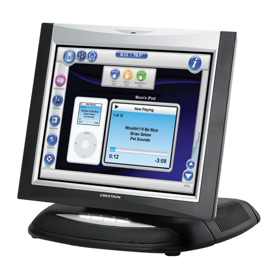
SMK-12/15/17 Swivel Mount Kit ST-PK Programming Cable Kit The latest software versions can be obtained from the Crestron website. Refer to the NOTE following these footnotes. Crestron 2-Series control systems include the AV2 and PRO2. Consult the latest Crestron Product Catalog for a complete list of 2-Series control systems. - Page 10 Tilt Touchpanels Crestron Isys TPS-12B Angled View TPS-15W Angled View TPS-17B Front View ¥ Tilt Touchpanels: TPS-12B/W, TPS-15B/W & TPS-17B/W TPS-12B/W, TPS-15B/W & TPS-17B/W Operations Guide – DOC. 6464...
- Page 11 TPS-12B/W Physical View – Front 12.85 in (32.64 cm) 10.43 in (26.49 cm) 12 inch 12.15 in (30.86 cm) TPS-12B/W Physical Views – Side View at Maximum and Minimum Elevation 45° 12.15 in 10.70 in (30.86 cm) (27.18 cm) 12.40 in (31.50 cm) Tilt Touchpanels: TPS-12B/W, TPS-15B/W &...
- Page 12 TPS-15B/W Physical View – Front (34.21 cm) TPS-17B/W Physical View – Front (34.21 cm) NOTE: The TPS-15BW and TPS-17BW are the same height. ¥ Tilt Touchpanels: TPS-12B/W, TPS-15B/W & TPS-17B/W TPS-12B/W, TPS-15B/W & TPS-17B/W 11.94 in (30.33 cm) 13.47 in 11.94 in...
- Page 13 Bottom View (24.38 cm) View of Rear Connectors – Cover Removed Operations Guide – DOC. 6464 11.61 in (29.49 cm) 7.00 in (17.78 cm) 9.60 in 8.40 in (21.34 cm) Tilt Touchpanels: TPS-12B/W, TPS-15B/W & TPS-17B/W ¥ 9 Tilt Touchpanels 45°...
- Page 14 Crestron Isys Ports and Pushbuttons All connections to the TPS-12B/W, TPS-15B/W & TPS-17B/W are made through the ports on the rear panel. Refer to the illustrations and descriptions that follow. NOTE: Rear ports are not accessible after the cover is replaced.
- Page 15 The four-pin 5 mm detachable terminal block provides communication with and power from a Cresnet control network. For additional details, refer to “Network Wiring” on page 15. A cable for this connection is provided with the touchpanel. Pins 24 and G provide 24 VDC and ground.
- Page 16 This eight-pin RJ-45 connection provides connectivity to the CNX-PVID or the TPMC-CH-IMC interface module. This port provides component, composite or S-video balanced input to the touchpanel over Crestron Certified Wiring. Description of the pinouts is shown in the following table. A cable for this connection is provided with the touchpanel.
- Page 17 AUDIO I/O This 8-pin RJ-45 connector provides connectivity to the CNX-BIPAD or with the TPMC-CH-IMC interface module. This port uses Crestron Certified Wiring and provides audio input to the touchpanel and microphone output from the touchpanel. A description of the pinouts is shown in the following table.
-
Page 18: Tilt Angle Tension Adjustment
Cresnet cable must account for limits based upon the touchpanel power requirements. Refer to the latest version of the TPMC-CH-IMC Interface Module Operations Guide (Doc. 6345) available on the Crestron website and “Network Wiring” on page 15. Tilt Angle Tension Adjustment Use a 5/32 inch socket (supplied by other) with a hex drive key (Allen wrench) to increase or decrease pivot tension at the base of the touchscreen. -
Page 19: Setup
Cresnet power usage of the entire chain. If the unit is a home-run from a Crestron system power supply network port, the Cresnet power usage of that unit is the Cresnet power usage of the entire run. The wire gauge and the Cresnet power usage of the run should be used in the following equation to calculate the cable length value on the equation’s left side. -
Page 20: Quickmedia Network Wiring
The aggregate cable length of a signal path originating at a QM transmitter and terminating at the TPS-12B/W, TPS-15B/W & TPS-17B/W must not exceed 328 feet (100 meters). Video signals may experience a loss of quality over very long lengths of cable. -
Page 21: Configuring The Touchpanel
The MAIN MENU for configuring the touchpanel appears when a finger is held to the touchscreen as power is applied, or after the hardware reset button is pressed and released. -
Page 22: Calibration Menu
NOTE: For convenience, the current CRESNET ID setting is displayed in the upper left corner. NOTE: All touchpanel settings are automatically saved in non-volatile memory. ¥ Tilt Touchpanels: TPS-12B/W, TPS-15B/W & TPS-17B/W TPS-12B/W, TPS-15B/W & TPS-17B/W Operations Guide – DOC. 6464... -
Page 23: Interface Menu
SIMPL Windows program is required if data is to be successfully transferred. Net ID for the TPS-12B/W, TPS-15B/W & TPS-17B/W is factory set to 03. No two devices in the same system can have the same Net ID. - Page 24 Disable to prohibit any CIP connection. CIP must be enabled for the touchpanel to communicate with other Crestron Ethernet devices. NOTE: The TPS-12B/W, TPS-15B/W & TPS-17B/W do not support a wireless Ethernet connection. Select the Return button located on the INTERFACE MENU to return to the SETUP MENU.
- Page 25 Touch Output (communication of touch coordinates to an external device) • Mouse Input (allows a mouse to control the touchpanel) • External Touch Input (allows another touchpanel to control the touchpanel) • Tilt Touchpanels: TPS-12B/W, TPS-15B/W & TPS-17B/W ¥ 21 Tilt Touchpanels...
- Page 26 After these parameters have been set, select the Return button to return to the SETUP MENU. QM SETUP Refer to the following table for additional QM SETUP MENU details. QM Setup Details ¥ Tilt Touchpanels: TPS-12B/W, TPS-15B/W & TPS-17B/W TPS-12B/W, TPS-15B/W & TPS-17B/W QM SETUP SCREEN CONTROLS Auto Compensation Turns off auto compensation.
- Page 27 Audio Settings button returns all audio parameters to their default settings when the button is selected. After audio parameters have been set, select the Return button to return to the SETUP MENU. GENERAL AUDIO SETUP MENU Operations Guide – DOC. 6464 Tilt Touchpanels: TPS-12B/W, TPS-15B/W & TPS-17B/W ¥ 23 Tilt Touchpanels...
- Page 28 QM Program Volume and Mic input volumes. Refer to the following table for additional GENERAL AUDIO SETUP MENU setup details. General Audio Setup Details Continued on next page ¥ Tilt Touchpanels: TPS-12B/W, TPS-15B/W & TPS-17B/W TPS-12B/W, TPS-15B/W & TPS-17B/W AUDIO MENU CONTROLS Play Test WAV File Plays a short WAV audio file.
-
Page 29: Video Menu
Adjusts the QM Mic 1 input level with the PLUS (+) and MINUS (-) buttons. QM Mic 2 Volume Adjusts the QM Mic 2 input level with the PLUS (+) and MINUS (-) buttons. Tilt Touchpanels: TPS-12B/W, TPS-15B/W & TPS-17B/W ¥ 25 Tilt Touchpanels DESCRIPTION... - Page 30 “QM Audio signal detected ID” will not appear. QM Video Setup Details * Video default is 0 for each of the video parameters (brightness, contrast, saturation, and hue). ¥ Tilt Touchpanels: TPS-12B/W, TPS-15B/W & TPS-17B/W TPS-12B/W, TPS-15B/W & TPS-17B/W VIDEO SCREEN...
-
Page 31: Diagnostics Menu
Diagnostics Menu The Diagnostics button from the MAIN MENU contains controls for diagnostic tools. The diagnostic tools should only be used under supervision from a Crestron customer service representative during telephone support. The options available from the DIAGNOSTICS MENU are numeric in nature and their interpretation is beyond the scope of this manual. - Page 32 Refer to the following diagram for access to the connectors and cable routing. Access to I/O Panel and Cable Routing The TPS-12B/W, TPS-15B/W & TPS-17B/W touchpanels have rubber pads on the underside of its base so that it can rest on a horizontal surface. Make the required connections as shown and described in the following sections.
-
Page 33: Recommended Cleaning
Wipe touchscreen clean and avoid getting moisture beneath the bezels. Operations Guide – DOC. 6464 USB: RESERVED FOR FUTURE APPLICATION HEADPHONES COMPACT FLASH Tilt Touchpanels: TPS-12B/W, TPS-15B/W & TPS-17B/W ¥ 29 Tilt Touchpanels AUDIO I/O: BALANCED AUDIO IN & MIC OUT VIDEO IN: BALANCED VIDEO INPUT... -
Page 34: Programming Software
Have a question or comment about Crestron software? Answers to frequently asked questions (FAQs) can be viewed in the Online Help section of the Crestron website. To post a question or view questions you have submitted to Crestron’s True Blue Support, log in at http://support.crestron.com. -
Page 35: Earliest Version Software Requirements For The Pc
Crestron Isys TPS-12B/W, TPS-15B/W & TPS-17B/W Earliest Version Software Requirements for the PC NOTE: Crestron recommends that you use the latest software to take advantage of the most recently released features. The latest software is available from the Crestron website. -
Page 36: Programming With Simpl Windows
It provides a well-designed graphical environment with a number of workspaces (i.e., windows) in which a programmer can select, configure, program, test, and monitor a Crestron control system. SIMPL Windows offers drag and drop functionality in a familiar Windows This section describes a sample SIMPL Windows program that includes a TPS-12BW touchpanel. -
Page 37: C2Net-Device Slot In Configuration Manager
Device Library and drop it on the C2Net-Device Slot. The PRO2 system tree displays the touchpanel in Slot 9, with a default Net ID of 03, as shown in the following illustration. Additional touchpanels will be added with the next available Net ID number. -
Page 38: Example Program
TPS-12B/W, TPS-15B/W & TPS-17B/W touchpanels. For additional information about Device Extenders, refer to the latest version of the Crestron SIMPL Windows Symbol Guide (Doc. 6120), or the on-line help included with SIMPL Windows. Example Program An example program for the TPS-12B/W, TPS-15B/W &... -
Page 39: Programming With Visiontools Pro-E
WAV files to a touchpanel project. Pre-recorded WAV files for voice prompts and responses are available from Crestron. These files can be stored into and programmed for use in the touchpanel directly or may be edited with the Sound Recorder. For example, the individual files can be combined to create custom messages. - Page 40 A bit depth refers to the number of memory bits used to store color data for each pixel in a raster image. A touchpanel raster image consists of a rectangular grid of picture elements (pixels). Each pixel uses the same amount of memory to store its color data.
-
Page 41: Hard Button Programming
Chinese fonts contain several thousand characters. Other multibyte languages include Japanese and Korean. Operations Guide – DOC. 6464 VT Pro-e “Image Properties” Window – Bit Depth Selection Join Join Join Join Tilt Touchpanels: TPS-12B/W, TPS-15B/W & TPS-17B/W ¥ 37 Tilt Touchpanels ) in a font. For... -
Page 42: Uploading And Upgrading
SIMPL Windows. In other words, you cannot enter Chinese character interspersed with numbers. You can enter Chinese characters or numbers in separate strings. Crestron is scheduling time to fix this in the near future and the release notes for SIMPL Windows will mention it. -
Page 43: Establishing Communications
1. Ensure that all devices are connected to the control processor and the control processor is connected via serial cable to the PC. 2. Open Crestron Toolbox and click Tools | Manage Address Book to display a list of available devices. Select Serial on COM1 as the connection type. - Page 44 TPS-12B/W, TPS-15B/W & TPS-17B/W “Address Book” Window – Serial Setup 3. After setting the correct parameters, click OK to return to the Crestron Toolbox main window. 4. Click Tools | Network Device Tree, or click the network device tree icon to display the devices in the system.
- Page 45 TPS-12B/W, TPS-15B/W & TPS-17B/W NOTE: Toolbox displays a customized list of functions depending on the type of device with which it is communicating. Operations Guide – DOC. 6464 Network Device Tree Sub-Menu -Functions Tilt Touchpanels: TPS-12B/W, TPS-15B/W & TPS-17B/W ¥ 41 Tilt Touchpanels...
- Page 46 Crestron Isys Direct Serial Communication Crestron devices that have an RS-232 port can be connected directly to a PC. To prepare the touchpanel for direct communication from a PC, refer to the following figure. Connect the RS-232 port of the computer directly to the RS-232 port of the touchpanel using Crestron Cable Number STCP-502PC.
- Page 47 Cresnet ID, connection parameters, memory usage, and hardware information. The Functions menu may now be used to upload a project, update firmware, and reset the network ID. Tilt Touchpanels: TPS-12B/W, TPS-15B/W & TPS-17B/W ¥ 43 Tilt Touchpanels . Select...
-
Page 48: Tcp/Ip Communication
NOTE: The list of functions depends on the type of device. TCP/IP Communication This section explains how to configure a TPS-12B/W, TPS-15B/W & TPS-17B/W to communicate over Ethernet using TCP/IP. These procedures assume that the touchpanel has been powered up and connected properly. - Page 49 CAT5 straight through cables with 8-pin RJ-45 connectors to connect the LAN port on the touchpanel and the LAN port on the PC to the Ethernet hub. Alternatively, you can use a CAT5 crossover cable to connect the two LAN ports directly, without using a hub.
- Page 50 ¥ Tilt Touchpanels: TPS-12B/W, TPS-15B/W & TPS-17B/W TPS-12B/W, TPS-15B/W & TPS-17B/W 5. Once the cable connections are made, open Crestron Toolbox and click Tools | Manage Address book to display the “Address Book” window. 6. Select the touchpanel from the address book or click Add Entry and type a new name for the new device, such as TPS.
- Page 51 TPS-12B/W, TPS-15B/W & TPS-17B/W Operations Guide – DOC. 6464 2. If the touchpanel already has an IP table, it is displayed at the top of the window. 3. Click Add Entry to add a new IP table entry or select an existing IP entry from the list and click Modify Entry.
-
Page 52: Troubleshooting Communications
Tilt Touchpanels Crestron Isys NOTE: When an IP table is sent to the touchpanel, the previously loaded IP table is overwritten. Troubleshooting Communications Use the following checklist if communication cannot be established with the control processor. Uploading a SIMPL Windows Program The SIMPL Windows file can be uploaded to the control system using SIMPL Windows or via the Crestron Toolbox. - Page 53 SIMPL program (if any), and permits you to stop, start, erase, retrieve, and upload a SIMPL program. This menu also permits you to upload to compact flash or internal flash. Tilt Touchpanels: TPS-12B/W, TPS-15B/W & TPS-17B/W ¥ 49 Tilt Touchpanels...
-
Page 54: Uploading A Vt Pro-E Project
Crestron Isys Uploading a VT Pro-e Project The VT Pro-e file can be uploaded to the touchpanel using VT Pro-e or via the Crestron Toolbox. The TPS-12B/W, TPS-15B/W & TPS-17B/W touchpanel source file has the extension .vtp. A compiled VT Pro-e file has the extension .vtz. - Page 55 Send Selected File Types sends only the file types that are • selected. Core Files are files that include touchpanel logic, join number • remapping, and other files related to touchpanel functionality. Tilt Touchpanels: TPS-12B/W, TPS-15B/W & TPS-17B/W ¥ 51 Tilt Touchpanels...
-
Page 56: Firmware Upgrade
To take advantage of all the touchpanel features, it is important that the unit contains the latest firmware. Please check the Crestron website for the latest version of firmware. Not every product has a firmware upgrade, but as Crestron improves functions, adds new features, and extends the capabilities of its products, firmware upgrades are posted. - Page 57 5. The “Firmware” window displays the model and current firmware version. Click Upload New Firmware. “Firmware” Window 6. When the following screen appears, browse to locate the firmware (.csf) file. Tilt Touchpanels: TPS-12B/W, TPS-15B/W & TPS-17B/W ¥ 53 Tilt Touchpanels...
- Page 58 Tilt Touchpanels Crestron Isys ¥ Tilt Touchpanels: TPS-12B/W, TPS-15B/W & TPS-17B/W TPS-12B/W, TPS-15B/W & TPS-17B/W Locate Firmware in the “Open” Window 7. Click Open and the file transfers to the unit. “File Transfer” Window 8. The “Firmware” window reopens indicating the new firmware version.
-
Page 59: Problem Solving
TPS-12B/W, TPS-15B/W & TPS-17B/W Problem Solving Troubleshooting The following table provides corrective action for possible trouble situations. If further assistance is required, please contact a Crestron customer service representative. TPS-12B/W, TPS-15B/W & TPS-17B/W Troubleshooting & TPS-17B/W does not respond to ping command. -
Page 60: Further Inquiries
For assistance in your local time zone, refer to the Crestron website (www.crestron.com) for a listing of Crestron worldwide offices. You can also log onto the online help section of the Crestron website to ask questions about Crestron products. First-time users will need to establish a user account to fully benefit from all available features. -
Page 61: Software License Agreement
This Agreement may only be modified by a writing signed by an authorized officer of Crestron. Updates may be licensed to You by Crestron with additional or different terms. This is the entire agreement between Crestron and You relating to the Software and it supersedes any prior representations, discussions, undertakings, communications or advertising relating to the Software. - Page 62 “applets” incorporated into the Software), the accompanying media and printed materials, and any copies of the Software are owned by Crestron or its suppliers. The Software is protected by copyright laws and international treaty provisions. Therefore, you must treat the Software like any other copyrighted material, subject to the provisions of this Agreement.
-
Page 63: Return And Warranty Policies
CRESTRON shall not be liable to honor the terms of this warranty if the product has been used in any application other than that for which it was intended, or if it has been subjected to misuse, accidental damage, modification, or improper installation procedures. - Page 64 Crestron Electronics, Inc. Operations Guide – DOC. 6464 5 Volvo Drive Rockleigh, NJ 07647 (2014556) Tel: 888.CRESTRON 03.06 Fax: 201.767.7576 Specifications subject to www.crestron.com change without notice.
Need help?
Do you have a question about the Isys TPS-12B and is the answer not in the manual?
Questions and answers