Table of Contents
Advertisement
Quick Links
Advertisement
Chapters
Table of Contents

Related Manuals for Axis 2N IP Verso


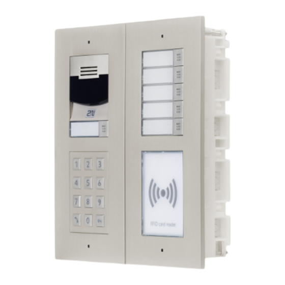
Summary of Contents for Axis 2N IP Verso
- Page 1 ® 2N IP Verso Modular IP Intercom Installation Manual Version: 2.13 www.2n.cz...
- Page 2 The 2N TELEKOMUNIKACE a.s. is a Czech manufacturer and supplier of telecommunications equipment. The product family developed by 2N TELEKOMUNIKACE a.s. includes GSM gateways, private branch exchanges (PBX), and door and lift communicators. 2N TELEKOMUNIKACE a.s. has been ranked among the Czech top companies for years and represented a symbol of stability and prosperity on the telecommunications market for almost two decades.
- Page 3 The 2N TELEKOMUNIKACE a.s. is the holder of the ISO 9001:2009 certificate. All development, production and distribution processes of the company are managed by this standard and guarantee a high quality, technical level and professional aspect of all our products.
-
Page 4: Table Of Contents
Content: 1. Product Overview 1.1 Components and Associated Products 1.2 Terms and Symbols 2. Description and Installation 2.1 Before You Start 2.2 Mechanical Installation 2.2.1 One Module Box 2.2.2 Two modules boxes 2.2.3 More Two Modules Boxes 2.2.4 Three Modules Box 2.2.5 More Three Modules Boxes 2.2.6 Tamper and I/O Module 2.2.7 Module dimensions... -
Page 5: Product Overview
1. Product Overview Here is what you can find in this section: 1.1 Components and Associated Products 1.2 Terms and Symbols 2N TELEKOMUNIKACE a.s., www.2n.cz 5/302... - Page 6 Basic Features ® IP Verso is an elegant and reliable intercom equipped with lots of useful functions. Thanks to SIP support and compatibility with major brands of PBX ® manufacturers, it can benefit from using VoIP networks. IP Verso can be used as a door or special purpose intercom for office buildings, residential areas and other applications.
- Page 7 Audio quality – using the automatic echo cancelling system, full duplex communication is available at any time. ® The installation of IP Verso is very easy, all you have to do is assemble the required parts and modules and attach the network cable. The modules are plug&play, so there is no need to configure them manually.
- Page 8 Advantages of Use Elegant design Weather resistant Various modes of installation (flush, surface, plasterboard) Sensitive microphone and loud speaker Both-way audio communication – acoustic echo cancellation Integrated colour HD camera with wide-angle lense and hidden night vision Selectable number of quick dial buttons with nametags and backlight Optional numeric keypad with backlight Option to have multiple modules of the same kind –...
-
Page 9: Components And Associated Products
1.1 Components and Associated Products Main Units 2N Part No. 9155101 Main unit Axis Part No. 01271- 2N Part No. 9155101B Main unit Axis Part No. 01272- Exposure to direct sunlight is not recommended. 2N TELEKOMUNIKACE a.s., www.2n.cz 9/302... - Page 10 2N Part No. 9155101C Main unit with camera Axis Part No. 01273- 2N Part No. Main unit with camera 9155101CB Exposure to direct sunlight is not recommended. Axis Part No. 01274- 2N TELEKOMUNIKACE a.s., www.2n.cz 10/302...
- Page 11 Caution There must be just one (with/without a camera) main unit in every installation. The main unit installation requires two frame/box positions; the other position, however, is left for additional module installation. One blind module is supplied with the main unit. 2N TELEKOMUNIKACE a.s., www.2n.cz 11/302...
- Page 12 Frames 2N Part No. 9155011 Flush mounting frame, 1 module Axis Part No. 01278-001 2N Part No. 9155011B Flush mounting frame, 1 module Axis Part No. 01279-001 2N Part No. 9155012 Flush mounting frame, 2 modules Axis Part No. 01281-001 2N TELEKOMUNIKACE a.s., www.2n.cz...
- Page 13 2N Part No. 9155012B Flush mounting frame, 2 modules Axis Part No. 01282-001 2N Part No. 9155013 Flush mounting frame, 3 modules Axis Part No. 01282-001 2N TELEKOMUNIKACE a.s., www.2n.cz 13/302...
- Page 14 2N Part No. 9155013B Flush mounting frame, 3 modules Axis Part No. 01283-001 2N Part No. 9155021 Surface mounting frame, 1 module Axis Part No. 01287-001 2N TELEKOMUNIKACE a.s., www.2n.cz 14/302...
- Page 15 2N Part No. 9155021B Surface mounting frame, 1 module Axis Part No. 01288-001 2N Part No. 9155022 Surface mounting box, 2 modules Axis Part No. 01289-001 2N TELEKOMUNIKACE a.s., www.2n.cz 15/302...
- Page 16 2N Part No. 9155022B Surface mounting box, 2 modules Axis Part No. 01290-001 2N Part No. 9155023 Surface mounting box, 3 modules Axis Part No. 01291-001 2N TELEKOMUNIKACE a.s., www.2n.cz 16/302...
- Page 17 2N Part No. 9155023B Surface mounting box, 3 modules Axis Part No. 01292-001 The 1-module frame is used when another module is added to the existing installation or when the module is mounted to an extended interconnecting cable for an outgoing reader, for example.
- Page 18 2N Part No. 9155030 ® IP Verso – Info panel Axis Part. No. 01252-001 The Infopanel module helps you place such information into the intercom installation as house number, opening hours and similar data. The Infopanel backlight is software controlled.
- Page 19 2N Part No. 9155047 ® IP Verso – Touch keypad Axis Part No. 01277-001 The numeric touch keypad module helps you dial users via their phonebook positions or phone numbers, control the lock and use other code-accessible functions. The keypad digits and symbols are backlit.
- Page 20 Part No. 9155082 ® IP Verso – Bluetooth & RFID reader 125kHz, 13.56MHz, NFC The bluetooth and card reader module provides you with access control via contactless cards or keyfobs. The module supports the following 125 kHz and 13.56 MHz cards or other carriers (only card serial number is read): ®...
- Page 21 2N Part No. 9155032 ® IP Verso – RFID Reader, 125 kHz Axis Part No. 01255-001 The card reader module provides you with access control via contactless cards or keyfobs. The module supports the 125 kHz EM- 41xx or HID Proximity cards.
- Page 22 2N Part No. 9137422E ® IP external Bluetooth reader (USB interface) Axis Part No. 01402-001 An external Bluetooth reader connecting to your computer via USB. It can be used to pair new users who want to use their ® smartphones and 2N Mobile Key application for access to controlled areas.
- Page 23 2N Part No. 9155035 ® IP Verso – 5 buttons Axis Part No. 01258-001 A module with 5 mechanical quick dial buttons. The buttons are backlit and can include nametags. 2N Part No. 9155036 ® IP Verso – Touch Display Axis Part No.
- Page 24 2N Part No. 9155038 ® IP Verso – Tamper switch Axis Part No. 01260-001 The module secures your system against tampering by detecting intercom opening or top frame removing. The module is installed on a special place and needs no separate position.
- Page 25 2N Part No. 9155041 ® IP Verso – Induction loop Axis Part No. 01263-001 The induction loop module is used to transmit an audio signal directly into a hearing aid via a magnetic field. 2N Part No. 9155042 ® IP Verso –...
- Page 26 2N Part No. 9155045 ® IP Verso – Fingerprint reader Axis Part No. 01276-001 The Fingerprint reader is used for verification of human fingers for access control and intercom control. 2N Part No. 9155050 1 m extension cable Axis Part No. 01267-001 Only one extension cable allowed.
- Page 27 2N Part No. 9155054 3 m extension cable Axis Part No. 01268-001 Only one extension cable allowed. Maximum bus length is 7 m. 2N Part No. 9155055 5 m extension cable Axis Part No. 01269-001 Only one extension cable allowed.
- Page 28 Mounting Accessories 2N Part No. 9155014 Flush mounting box Axis Part No. 01284-001 1 module Designed for flush or plasterboard mounting of 1-module sets and delivered including accessories for multiple box assemblies 2N Part No. 9155015 Flush mounting box Axis Part No. 01285-001...
- Page 29 2N Part No. 9155061 Backplate 1 module Axis Part No. 01293-001 For glass or uneven surface installation 2N Part No. 9155062 Backplate 2 modules Axis Part No. 01294-001 For glass or uneven surface installation 2N Part No. 9155063 Backplate 3 modules Axis Part No.
- Page 30 2N Part No. 9155064 Backplate 2 (w) x 2 (h) modules Axis Part No. 01296-001 For glass or uneven surface installation 2N Part No. 9155065 Backplate 3 (w) x 2 (h) modules Axis Part No. 01297-001 For glass or uneven surface installation 2N Part No.
- Page 31 2N Part No. 9155067 Backplate 3 (w) x 3 (h) modules Axis Part No. 01299-001 For glass or uneven surface installation Choose the proper frame and, if necessary, mounting box type depending on your ® ® particular IP Verso installation needs.
- Page 32 Internal Units and Accessories Part Nos: ® Indoor Touch – black 91378365, 01416-001 WiFi version (second Part No.) 91378366, 01419-001 ® The elegant internal touch panel, Indoor Touch is suitable for all 2N IP intercoms. On the panel’s display you can you find out who is at the door, but also start a conversation with the visitor, open the lock or turn on the light in the entrance hall.
- Page 33 91378382W, 01426-001 VoIP Phones Part No. 91378357 Grandstream GXV3240 VoIP video telephone Axis Part No. 01422-001 GXV3240 is the successor to the popular GXV3140 model, which allows for comfortable video calls in the IP network. Touchscreen and keypad control. Part No.
- Page 34 Electric Locks Part No. 932071E BEFO 11211 12 V / 230 mA DC low consumption Part No. 932081E BEFO 11221 with momentum pin 12 V / 230 mA DC low consumption For opening of the lock a short electrical impuls is sufficient, which unlocks the lock.
- Page 35 Part No. 932061E 211211 door signalling, low consumption 12 V / 230 mA A regular lock with a built-in contact to indicate whether the door is open or closed. Part No. 932072E 31211 fail-safe 12 V / 170 mA DC The failsafe lock is closed when electricity is switched on.
- Page 36 FAQ: Electric locks – Difference between locks in 2N IP intercom accesories Power Supply Part Nos: PoE injector – without cable 91378100, 01394-001 PoE injetor – with EU cable PoE injector – with US cable 91378100E For power supply of intercom via ethernet cable when PoE switch 91378100US, 01403- is not available.
- Page 37 Two-Wire Connection Part No. 9159014EU/US/UK ® 2Wire (set of 2 adaptors and power source for EU/US/UK) ® 2Wire converter allows you to use the existing wiring (2 wires) from your original door bell or door intercom to connect any IP device. You don’t ®...
- Page 38 RFID 13 MHz 2N Part No. 9159031 External 13.56 MHz Mifare RFID card reader, Wiegand Axis Part No. 01390-001 Secondary reader for connection to an internal reader. Allows control of card entry from both sides of the door. IP68 cover, also suitable for exteriors. Reads Mifare cards.
- Page 39 JIS X 6319 Felica ISO/IEC 18092 SmartPhone with NFC/HCE ® support, since Android version 4.3 (2N Mobile app required) EMarine 2N Part No. 9134173 Mifare Classic 1k RFID card, 13.56 MHz Axis Part No. 01384-001 2N TELEKOMUNIKACE a.s., www.2n.cz 39/302...
- Page 40 2N Part No. 9134174 Mifare Classic 1k RFID fob, 13.56 MHz Axis Part No. 01385-001 2N TELEKOMUNIKACE a.s., www.2n.cz 40/302...
- Page 41 RFID 125 kHz 2N Part No. 9159030 External 125 kHz RFID card reader Axis Part No. 01389- Secondary reader for connection to an internal reader. Allows control of card entry from both sides of the door. IP67 cover, also suitable for exteriors. Reads EM4100 and EM4102 cards.
- Page 42 2N Part No. 9134166E RFID fob, type EM4100, 125 kHz Axis Part No. 01396- Biometry 2N Part No. 9137423E ® IP intercom - external fingerprint reader (USB interface) Axis Part No. 01401-001 2N TELEKOMUNIKACE a.s., www.2n.cz 42/302...
- Page 43 2N Part No. 9159010 ® Security Relay Axis Part No. 01386- A handy add-on that significantly enhances door entry security as it prevents tampering with the intercom and forced opening of the lock. To be installed between intercom and lock, powered by the intercom.
- Page 44 Induction loop 2N Part No. 9155043 Induction loop module – antenna Axis Part No. 01265-001 External antenna boosts the range of usability of the induction loop, so that the hearing impared user of hearing aid with telecoil can receive the audio signal in wider area. It has to be used with Part No.
- Page 45 A button for logic input connection for opening a door inside a building. Part No. 9154004 Water-proof metal button Axis Part No. 01479-001 2N Part No. 9159012 Magnetic door contact Axis Part No. 01388-001 Door installation set that enables the status of door opening to be ascertained.
- Page 46 Additional Modules 2N Part No. 9159011 ® Wiegand Isolator is designed for galvanic isolation of Axis Part No. 01387- two devices separately power supplied and interconnected via the ® Wiegand bus. The Wiegand Isolator protects the interconnected devices against communication errors and/or damage.
- Page 47 License 2N Part No. Enhanced Audio 9137905 Axis Part No. 01376-001 2N Part No. Enhanced Video 9137906 Axis Part No. 01377-001 2N Part No. Enhanced Integration 9137907 Axis Part No. 01378-001 2N Part No. Enhanced Security 9137908 Axis Part No.
- Page 48 Refer to the Configuration Manual for 2N IP intercoms, Subs. Function Licensing for details. For more accessories and particular advice please contact your local distributor of 2N products. 2N TELEKOMUNIKACE a.s., www.2n.cz 48/302...
-
Page 49: Terms And Symbols
1.2 Terms and Symbols The following symbols and pictograms are used in the manual: Safety Always abide by this information to prevent persons from injury. Warning Always abide by this information to prevent damage to the device. Caution Important information for system functionality. Useful information for quick and efficient functionality. -
Page 50: Description And Installation
2. Description and Installation Here is what you can find in this section: 2.1 Before You Start 2.2 Mechanical Installation 2.3 Electric Installation 2.4 Extending Module Connection 2.5 Completion 2N TELEKOMUNIKACE a.s., www.2n.cz 50/302... - Page 51 Product Completeness Check Before you start please check whether the contents of the package of your new ® IP Verso complies with the following list. ® 1x 2N IP Verso 2N TELEKOMUNIKACE a.s., www.2n.cz 51/302...
-
Page 52: Mechanical Installation
2.2 Mechanical Installation Mounting Types Overview Refer to the table below for a list of mounting types and necessary components. You can assemble multiple units in all mounting types. Flush mounting – classic bricks incl. hollow bricks, thermally insulated walls, etc. What you need for mounting: a properly cut hole as instructed in the box package Plaster, mounting glue, mounting foam or mortar as necessary... - Page 53 Surface mounting concrete and steel structures, entry barrier columns, interior, etc. What you need for mounting: ® IP Verso plus the respective frames 1x module: frame Part No. 9155021 2x modules: frame Part No. 9155022 3x modules: frame Part No. 9155023 For not flat surface use according to the module number backplate Part No 9155061 –...
- Page 54 Caution The warranty does not apply to the product defects and failures arisen as a result of improper mounting (in contradiction herewith). The manufacturer is neither liable for damage caused by theft within an area that is accessible after the attached electric lock is switched. The product is not designed as a burglar protection device except when used in combination with a standard lock, which has the security function.
- Page 55 Caution Make sure that the diameter of the dowel holes is accurate to avoid falling out of the dowels! Use the mounting glue to secure the dowels if necessary. Make sure that the depth of the dowel holes is accurate! Do not use low-quality dowels to avoid their pulling out of the wall! Having removed the front panel, make sure that no dirt gets inside the product (especially onto the sealing surface).
- Page 56 Warning! It is forbidden to use silicone or any other sealing material on the marked and hatched places. 2N TELEKOMUNIKACE a.s., www.2n.cz 56/302...
-
Page 57: One Module Box
Safety Eliminate the risk of personal injury! Surface mounting is not recommended for narrow passages or places where people's attention is distracted by something else. The manufacturer shall not be liable for injuries in such cases! Module Installation 2.2.1 One Module Box 2.2.2 Two modules boxes 2.2.3 More Two Modules Boxes 2.2.4 Three Modules Box... - Page 58 2N TELEKOMUNIKACE a.s., www.2n.cz 58/302...
- Page 59 2N TELEKOMUNIKACE a.s., www.2n.cz 59/302...
- Page 60 Flush mounting box mounting – plasterboard 2N TELEKOMUNIKACE a.s., www.2n.cz 60/302...
- Page 61 2N TELEKOMUNIKACE a.s., www.2n.cz 61/302...
- Page 62 2N TELEKOMUNIKACE a.s., www.2n.cz 62/302...
- Page 63 Flush module mounting 2N TELEKOMUNIKACE a.s., www.2n.cz 63/302...
- Page 64 2N TELEKOMUNIKACE a.s., www.2n.cz 64/302...
- Page 65 2N TELEKOMUNIKACE a.s., www.2n.cz 65/302...
- Page 66 2N TELEKOMUNIKACE a.s., www.2n.cz 66/302...
- Page 67 2N TELEKOMUNIKACE a.s., www.2n.cz 67/302...
- Page 68 Surface module mounting 2N TELEKOMUNIKACE a.s., www.2n.cz 68/302...
- Page 69 2N TELEKOMUNIKACE a.s., www.2n.cz 69/302...
- Page 70 2N TELEKOMUNIKACE a.s., www.2n.cz 70/302...
- Page 71 2N TELEKOMUNIKACE a.s., www.2n.cz 71/302...
- Page 72 2N TELEKOMUNIKACE a.s., www.2n.cz 72/302...
-
Page 73: Two Modules Boxes
2.2.2 Two modules boxes Flush mounting box mounting – classics bricks 2N TELEKOMUNIKACE a.s., www.2n.cz 73/302... - Page 74 2N TELEKOMUNIKACE a.s., www.2n.cz 74/302...
- Page 75 2N TELEKOMUNIKACE a.s., www.2n.cz 75/302...
- Page 76 2N TELEKOMUNIKACE a.s., www.2n.cz 76/302...
- Page 77 2N TELEKOMUNIKACE a.s., www.2n.cz 77/302...
- Page 78 2N TELEKOMUNIKACE a.s., www.2n.cz 78/302...
- Page 79 2N TELEKOMUNIKACE a.s., www.2n.cz 79/302...
- Page 80 Flush mounting box mounting – plasterboard 2N TELEKOMUNIKACE a.s., www.2n.cz 80/302...
- Page 81 2N TELEKOMUNIKACE a.s., www.2n.cz 81/302...
- Page 82 2N TELEKOMUNIKACE a.s., www.2n.cz 82/302...
- Page 83 2N TELEKOMUNIKACE a.s., www.2n.cz 83/302...
- Page 84 2N TELEKOMUNIKACE a.s., www.2n.cz 84/302...
- Page 85 2N TELEKOMUNIKACE a.s., www.2n.cz 85/302...
- Page 86 Flush module mounting 2N TELEKOMUNIKACE a.s., www.2n.cz 86/302...
- Page 87 2N TELEKOMUNIKACE a.s., www.2n.cz 87/302...
- Page 88 2N TELEKOMUNIKACE a.s., www.2n.cz 88/302...
- Page 89 2N TELEKOMUNIKACE a.s., www.2n.cz 89/302...
- Page 90 2N TELEKOMUNIKACE a.s., www.2n.cz 90/302...
- Page 91 2N TELEKOMUNIKACE a.s., www.2n.cz 91/302...
- Page 92 2N TELEKOMUNIKACE a.s., www.2n.cz 92/302...
- Page 93 2N TELEKOMUNIKACE a.s., www.2n.cz 93/302...
- Page 94 2N TELEKOMUNIKACE a.s., www.2n.cz 94/302...
- Page 95 2N TELEKOMUNIKACE a.s., www.2n.cz 95/302...
- Page 96 Surface module mounting 2N TELEKOMUNIKACE a.s., www.2n.cz 96/302...
- Page 97 2N TELEKOMUNIKACE a.s., www.2n.cz 97/302...
- Page 98 2N TELEKOMUNIKACE a.s., www.2n.cz 98/302...
- Page 99 2N TELEKOMUNIKACE a.s., www.2n.cz 99/302...
- Page 100 2N TELEKOMUNIKACE a.s., www.2n.cz 100/302...
- Page 101 2N TELEKOMUNIKACE a.s., www.2n.cz 101/302...
- Page 102 2N TELEKOMUNIKACE a.s., www.2n.cz 102/302...
- Page 103 2N TELEKOMUNIKACE a.s., www.2n.cz 103/302...
- Page 104 2N TELEKOMUNIKACE a.s., www.2n.cz 104/302...
- Page 105 2N TELEKOMUNIKACE a.s., www.2n.cz 105/302...
-
Page 106: More Two Modules Boxes
2.2.3 More Two Modules Boxes Flush mounting box mounting – classics bricks 2N TELEKOMUNIKACE a.s., www.2n.cz 106/302... - Page 107 2N TELEKOMUNIKACE a.s., www.2n.cz 107/302...
- Page 108 2N TELEKOMUNIKACE a.s., www.2n.cz 108/302...
- Page 109 2N TELEKOMUNIKACE a.s., www.2n.cz 109/302...
- Page 110 2N TELEKOMUNIKACE a.s., www.2n.cz 110/302...
- Page 111 2N TELEKOMUNIKACE a.s., www.2n.cz 111/302...
- Page 112 2N TELEKOMUNIKACE a.s., www.2n.cz 112/302...
- Page 113 2N TELEKOMUNIKACE a.s., www.2n.cz 113/302...
- Page 114 2N TELEKOMUNIKACE a.s., www.2n.cz 114/302...
- Page 115 Flush mounting box mounting – plasterboard 2N TELEKOMUNIKACE a.s., www.2n.cz 115/302...
- Page 116 2N TELEKOMUNIKACE a.s., www.2n.cz 116/302...
- Page 117 2N TELEKOMUNIKACE a.s., www.2n.cz 117/302...
- Page 118 2N TELEKOMUNIKACE a.s., www.2n.cz 118/302...
- Page 119 2N TELEKOMUNIKACE a.s., www.2n.cz 119/302...
- Page 120 2N TELEKOMUNIKACE a.s., www.2n.cz 120/302...
- Page 121 2N TELEKOMUNIKACE a.s., www.2n.cz 121/302...
- Page 122 2N TELEKOMUNIKACE a.s., www.2n.cz 122/302...
- Page 123 Flush module mounting 2N TELEKOMUNIKACE a.s., www.2n.cz 123/302...
- Page 124 2N TELEKOMUNIKACE a.s., www.2n.cz 124/302...
- Page 125 2N TELEKOMUNIKACE a.s., www.2n.cz 125/302...
- Page 126 2N TELEKOMUNIKACE a.s., www.2n.cz 126/302...
- Page 127 2N TELEKOMUNIKACE a.s., www.2n.cz 127/302...
- Page 128 2N TELEKOMUNIKACE a.s., www.2n.cz 128/302...
- Page 129 2N TELEKOMUNIKACE a.s., www.2n.cz 129/302...
- Page 130 2N TELEKOMUNIKACE a.s., www.2n.cz 130/302...
- Page 131 2N TELEKOMUNIKACE a.s., www.2n.cz 131/302...
- Page 132 2N TELEKOMUNIKACE a.s., www.2n.cz 132/302...
- Page 133 2N TELEKOMUNIKACE a.s., www.2n.cz 133/302...
- Page 134 2N TELEKOMUNIKACE a.s., www.2n.cz 134/302...
- Page 135 2N TELEKOMUNIKACE a.s., www.2n.cz 135/302...
- Page 136 Surface module mounting 2N TELEKOMUNIKACE a.s., www.2n.cz 136/302...
- Page 137 2N TELEKOMUNIKACE a.s., www.2n.cz 137/302...
- Page 138 2N TELEKOMUNIKACE a.s., www.2n.cz 138/302...
- Page 139 2N TELEKOMUNIKACE a.s., www.2n.cz 139/302...
- Page 140 2N TELEKOMUNIKACE a.s., www.2n.cz 140/302...
- Page 141 2N TELEKOMUNIKACE a.s., www.2n.cz 141/302...
- Page 142 2N TELEKOMUNIKACE a.s., www.2n.cz 142/302...
- Page 143 2N TELEKOMUNIKACE a.s., www.2n.cz 143/302...
- Page 144 2N TELEKOMUNIKACE a.s., www.2n.cz 144/302...
- Page 145 2N TELEKOMUNIKACE a.s., www.2n.cz 145/302...
- Page 146 2N TELEKOMUNIKACE a.s., www.2n.cz 146/302...
- Page 147 2N TELEKOMUNIKACE a.s., www.2n.cz 147/302...
-
Page 148: Three Modules Box
2.2.4 Three Modules Box Flush mounting box mounting – classics bricks 2N TELEKOMUNIKACE a.s., www.2n.cz 148/302... - Page 149 2N TELEKOMUNIKACE a.s., www.2n.cz 149/302...
- Page 150 2N TELEKOMUNIKACE a.s., www.2n.cz 150/302...
- Page 151 2N TELEKOMUNIKACE a.s., www.2n.cz 151/302...
- Page 152 2N TELEKOMUNIKACE a.s., www.2n.cz 152/302...
- Page 153 2N TELEKOMUNIKACE a.s., www.2n.cz 153/302...
- Page 154 2N TELEKOMUNIKACE a.s., www.2n.cz 154/302...
- Page 155 Flush mounting box mounting – plasterboard 2N TELEKOMUNIKACE a.s., www.2n.cz 155/302...
- Page 156 2N TELEKOMUNIKACE a.s., www.2n.cz 156/302...
- Page 157 2N TELEKOMUNIKACE a.s., www.2n.cz 157/302...
- Page 158 2N TELEKOMUNIKACE a.s., www.2n.cz 158/302...
- Page 159 2N TELEKOMUNIKACE a.s., www.2n.cz 159/302...
- Page 160 2N TELEKOMUNIKACE a.s., www.2n.cz 160/302...
- Page 161 Flush module mounting 2N TELEKOMUNIKACE a.s., www.2n.cz 161/302...
- Page 162 2N TELEKOMUNIKACE a.s., www.2n.cz 162/302...
- Page 163 2N TELEKOMUNIKACE a.s., www.2n.cz 163/302...
- Page 164 2N TELEKOMUNIKACE a.s., www.2n.cz 164/302...
- Page 165 2N TELEKOMUNIKACE a.s., www.2n.cz 165/302...
- Page 166 2N TELEKOMUNIKACE a.s., www.2n.cz 166/302...
- Page 167 2N TELEKOMUNIKACE a.s., www.2n.cz 167/302...
- Page 168 2N TELEKOMUNIKACE a.s., www.2n.cz 168/302...
- Page 169 2N TELEKOMUNIKACE a.s., www.2n.cz 169/302...
- Page 170 2N TELEKOMUNIKACE a.s., www.2n.cz 170/302...
- Page 171 2N TELEKOMUNIKACE a.s., www.2n.cz 171/302...
- Page 172 2N TELEKOMUNIKACE a.s., www.2n.cz 172/302...
- Page 173 2N TELEKOMUNIKACE a.s., www.2n.cz 173/302...
- Page 174 Surface module mounting 2N TELEKOMUNIKACE a.s., www.2n.cz 174/302...
- Page 175 2N TELEKOMUNIKACE a.s., www.2n.cz 175/302...
- Page 176 2N TELEKOMUNIKACE a.s., www.2n.cz 176/302...
- Page 177 2N TELEKOMUNIKACE a.s., www.2n.cz 177/302...
- Page 178 2N TELEKOMUNIKACE a.s., www.2n.cz 178/302...
- Page 179 2N TELEKOMUNIKACE a.s., www.2n.cz 179/302...
- Page 180 2N TELEKOMUNIKACE a.s., www.2n.cz 180/302...
- Page 181 2N TELEKOMUNIKACE a.s., www.2n.cz 181/302...
- Page 182 2N TELEKOMUNIKACE a.s., www.2n.cz 182/302...
- Page 183 2N TELEKOMUNIKACE a.s., www.2n.cz 183/302...
- Page 184 2N TELEKOMUNIKACE a.s., www.2n.cz 184/302...
- Page 185 2N TELEKOMUNIKACE a.s., www.2n.cz 185/302...
- Page 186 2N TELEKOMUNIKACE a.s., www.2n.cz 186/302...
- Page 187 2N TELEKOMUNIKACE a.s., www.2n.cz 187/302...
-
Page 188: More Three Modules Boxes
2.2.5 More Three Modules Boxes Flush mounting box mounting – classics bricks 2N TELEKOMUNIKACE a.s., www.2n.cz 188/302... - Page 189 2N TELEKOMUNIKACE a.s., www.2n.cz 189/302...
- Page 190 2N TELEKOMUNIKACE a.s., www.2n.cz 190/302...
- Page 191 2N TELEKOMUNIKACE a.s., www.2n.cz 191/302...
- Page 192 2N TELEKOMUNIKACE a.s., www.2n.cz 192/302...
- Page 193 2N TELEKOMUNIKACE a.s., www.2n.cz 193/302...
- Page 194 2N TELEKOMUNIKACE a.s., www.2n.cz 194/302...
- Page 195 2N TELEKOMUNIKACE a.s., www.2n.cz 195/302...
- Page 196 2N TELEKOMUNIKACE a.s., www.2n.cz 196/302...
- Page 197 Flush mounting box mounting – plasterboard 2N TELEKOMUNIKACE a.s., www.2n.cz 197/302...
- Page 198 2N TELEKOMUNIKACE a.s., www.2n.cz 198/302...
- Page 199 2N TELEKOMUNIKACE a.s., www.2n.cz 199/302...
- Page 200 2N TELEKOMUNIKACE a.s., www.2n.cz 200/302...
- Page 201 2N TELEKOMUNIKACE a.s., www.2n.cz 201/302...
- Page 202 2N TELEKOMUNIKACE a.s., www.2n.cz 202/302...
- Page 203 2N TELEKOMUNIKACE a.s., www.2n.cz 203/302...
- Page 204 2N TELEKOMUNIKACE a.s., www.2n.cz 204/302...
- Page 205 Flush module mounting 2N TELEKOMUNIKACE a.s., www.2n.cz 205/302...
- Page 206 2N TELEKOMUNIKACE a.s., www.2n.cz 206/302...
- Page 207 2N TELEKOMUNIKACE a.s., www.2n.cz 207/302...
- Page 208 2N TELEKOMUNIKACE a.s., www.2n.cz 208/302...
- Page 209 2N TELEKOMUNIKACE a.s., www.2n.cz 209/302...
- Page 210 2N TELEKOMUNIKACE a.s., www.2n.cz 210/302...
- Page 211 2N TELEKOMUNIKACE a.s., www.2n.cz 211/302...
- Page 212 2N TELEKOMUNIKACE a.s., www.2n.cz 212/302...
- Page 213 2N TELEKOMUNIKACE a.s., www.2n.cz 213/302...
- Page 214 2N TELEKOMUNIKACE a.s., www.2n.cz 214/302...
- Page 215 2N TELEKOMUNIKACE a.s., www.2n.cz 215/302...
- Page 216 2N TELEKOMUNIKACE a.s., www.2n.cz 216/302...
- Page 217 2N TELEKOMUNIKACE a.s., www.2n.cz 217/302...
- Page 218 2N TELEKOMUNIKACE a.s., www.2n.cz 218/302...
- Page 219 2N TELEKOMUNIKACE a.s., www.2n.cz 219/302...
- Page 220 Surface module mounting 2N TELEKOMUNIKACE a.s., www.2n.cz 220/302...
- Page 221 2N TELEKOMUNIKACE a.s., www.2n.cz 221/302...
- Page 222 2N TELEKOMUNIKACE a.s., www.2n.cz 222/302...
- Page 223 2N TELEKOMUNIKACE a.s., www.2n.cz 223/302...
- Page 224 2N TELEKOMUNIKACE a.s., www.2n.cz 224/302...
- Page 225 2N TELEKOMUNIKACE a.s., www.2n.cz 225/302...
- Page 226 2N TELEKOMUNIKACE a.s., www.2n.cz 226/302...
- Page 227 2N TELEKOMUNIKACE a.s., www.2n.cz 227/302...
- Page 228 2N TELEKOMUNIKACE a.s., www.2n.cz 228/302...
- Page 229 2N TELEKOMUNIKACE a.s., www.2n.cz 229/302...
- Page 230 2N TELEKOMUNIKACE a.s., www.2n.cz 230/302...
- Page 231 2N TELEKOMUNIKACE a.s., www.2n.cz 231/302...
- Page 232 2N TELEKOMUNIKACE a.s., www.2n.cz 232/302...
- Page 233 2N TELEKOMUNIKACE a.s., www.2n.cz 233/302...
-
Page 234: Tamper And I/O Module
2.2.6 Tamper and I/O Module 2N TELEKOMUNIKACE a.s., www.2n.cz 234/302... -
Page 235: Module Dimensions
2.2.7 Module dimensions Frames 9155011 - Flush mounting frame, 1 module 9155012 - Flush mounting frame, 2 modules 9155013 - Flush mounting frame, 3 modules 9155021 - Surface mounting frame, 1 module 2N TELEKOMUNIKACE a.s., www.2n.cz 235/302... - Page 236 9155022 - Surface mounting frame, 2 modules 9155023 - Surface mounting frame, 3 modules Backplates 9155061 - 1 module 9155062 - 2 modules 9155063 - 3 modules 9155064 - 2x2 modules 9155065 - 3x2 modules 9155065 - 2x3 modules 9155067 - 3x3 modules 2N TELEKOMUNIKACE a.s., www.2n.cz 236/302...
-
Page 237: Electric Installation
2.3 Electric Installation ® This subsection describes how to install the modules, how to connect the 2N Verso main unit to the power supply and LAN and how to connect other elements. Caution The device must be part of the electrical system of the building. Mounting Preparation Unscrew the second module cover on the main unit base. - Page 238 Version C – Additional Columns Unscrew the cover of the additional bases and take it out with a flat screwdriver. Insert the bases into each other as projected and secure their position with the small side wedges and screws. Place the cover on the flush mounting box / predrilled holes with dowels and pull the cables if any through the bottom holes.
- Page 239 LAN Connection ® IP Verso is connected to the Local Area Network (LAN) via the UTP/STP cable (Cat 5e or higher) terminated with an RJ-45 (LAN) connector. As the device is equipped with the Auto-MDIX function, both the straight and crossed cable can be used.
- Page 240 Legend LAN (PoE according to 802.1af) connector (PoE) IN1 terminals for input in passive/ active mode (−30 V to +30 V DC) OFF = open OR U > 1.5 V ON = closed contact OR U < 1.5 V OUT1 ®...
- Page 241 Output wiring diagram for Relay terminals The electric lock is opened by power supply connection. The magnetic lock is opened by power supply disconnection. Wiring Diagram of IN1 connector in active mod Wiring Diagram of IN1 connector in passive mod 2N TELEKOMUNIKACE a.s., www.2n.cz 241/302...
- Page 242 Reset Button Located among the main unit connectors, the Reset button helps you reset the factory default values, restart the device, find the device IP address and switch the static /dynamic mode. Factory Reset Follow the instructions below to reset the factory default values Press and hold the RESET button.
- Page 243 Static IP Address Setting Follow the instructions below to switch on the Static IP address mode (DHCP OFF): Press and hold the REST button. Wait until the red and green LEDs on the device come on simultaneously (approx. 20 s). Wait until the red LED goes off (approx.
- Page 244 Device Restart Press the RESET button shortly (< 1 s) to restart the system without changing configuration. Available Switches Location Name Description Main Unit Relay 1 Passive switch: NO/NC contact, up to 30 V / 1 A AC/DC Output Active switch output: 8 up to 12 V DC depending on power supply (PoE: 10 V;...
- Page 245 Warning When you connect a device containing a coil, such as a relay or an electromagnetic lock, it is necessary to protect the intercom against voltage peak while switching off the induction load. For this way of protection we recommend a diode 1 A / 1000 V (e.g., 1N4007, 1N5407, 1N5408) connected antiparallel to the device.
- Page 246 HW version 4 and higher 2N TELEKOMUNIKACE a.s., www.2n.cz 246/302...
- Page 247 HW version 3 and lower 2N TELEKOMUNIKACE a.s., www.2n.cz 247/302...
-
Page 248: Extending Module Connection
2.4 Extending Module Connection ® IP Verso allows to connect the following extending modules: Infopanel Keypad Touch Keypad RFID Card Reader 125 kHz RFID Card Reader 13.56 MHz RFID Card Reader 13.56 MHz NFC Support Secured RFID Card Reader 13.56 MHz NFC Support Bluetooth &... - Page 249 You can order a separate 1 m long bus cable (9155050) for remote installation of the ® IP Verso modules. Typically, it helps install an RFID card reader on the opposite ® side of the wall on which the IP Verso intercom is installed.
- Page 250 Module Externally Internally Internally mounted mounted (visible mounted (invisible on bottom base module) module) edge Infopanel Keypad Touch keypad RFID card reader 125 kHz RFID card reader 13.56 MHz RFID card reader 13.56 MHz ...
- Page 251 Module Externally Internally Internally mounted mounted (visible mounted (invisible on bottom base module) module) edge 5-button Wiegand Tamper switch Blind Security Relay Module Power Supply ® Except for the protection switch module, all the IP Verso modules are powered from the bus.
- Page 252 Main unit Consumption [W] (571v3) (Maximum value) LED – ringing 0.072 LED – lock 0.072 LED – secured 0.096 Button backlight 0.072 Name tag backlight 0.072 Unit backlight 0.072 Relay 1 0.132 OUT 1 Audio 2.94 Total 13.84 Module Idle consumption Full load [ Special elements (Maximum...
- Page 253 Module Idle consumption Full load [ Special elements (Maximum (Minimum value) value) RFID card reader 13.56 MHz NFC 0.44 0.82 Secured RFID card reader 13.56 MHz 0.44 0.82 Bluetooth & RFID reader 125kHz, 13.56 1.34 2.74 MHz, NFC Bluetooth &...
-
Page 254: Infopanel
Module Minimum consumption [W] Maximum consumption [W] Main unit with camera 2.36 11.57 RFID card reader 13.56 MHz 0.44 0.82 0.31 0.65 5-button 0.19 1.16 Touch display 0.19 1.70 0.31 0.65 Tamper switch 0.31 0.65 Wiegand 0.46 0.46 Bluetooth reader 0.20 0.67 Total... -
Page 255: Keypad
The module package includes a 220 mm long interconnecting cable. Nametag dimensions: 69,2 (W) x 86,7 (H) mm (dimensional tolerance: +0; -0,5 mm). Refer to www.2n.cz for printing template. Keypad ® The Keypad (Part No. 9155031) is one of the IP Verso intercom elements and provides a numerical input in the system. -
Page 256: Rfid Card Reader 13.56 Mhz
The following RFID cards can be read: EM4100, EM4102, HID Proximity RFID Card Reader 13.56 MHz ® The 13.56 MHz RFID card reader (Part No. 9155033) is one of the 2N IP Verso intercom elements and is used for reading RFID card Ids in the 13.56 MHz band. ®... -
Page 257: Secured Rfid Card Reader
Secured RFID Card Reader 13.56 MHz NFC support The Secured RFID card reader 13.56 MHz NFC support (Part No. 9155042) is one of the ® IP Verso intercom elements and is used for reading RFID card Ids in the 13.56 MHz band. -
Page 258: Bluetooth & Rfid Reader 125Khz, Secured 13.56Mhz, Nfc
ISO14443A Mifare Classic 1k & 4k, DESFire EV1, Mini, Plus S&X, SmartMX, Ultralight, Ultralight C, SLE44R35, my-d move (SLE66Rxx), PayPass, Legic Advant ISO14443B Calypso, CEPAS, Moneo, SRI512, SRT512, SRI4K, SRIX4K, PicoPass, HID iCLASS To accelerate card reading, you are recommended to select the card types used by the user in the module settings. -
Page 259: Touch Keypad & Rfid Reader
To accelerate card reading, you are recommended to select the card types used by the user in the module settings. Touch keypad & RFID reader 125kHz, 13.56MHz, NFC The touch keypad with a combined 125 kHz and 13.56 MHz card reader (Part No. ®... -
Page 260: Touch Keypad & Rfid Reader
To accelerate card reading, you are recommended to select the card types used by the user in the module settings. Touch keypad & RFID reader 125kHz, secured 13.56MHz, NFC The touch keypad with a combined 125 kHz and secured 13.56 MHz card (Part No. ®... - Page 261 Induction Loop ® Induction loop is one of the IP Verso intercom elements and is used to transmit an audio signal directly into a hearing aid via a magnetic field. ® The module contains two IP Verso bus connectors. These two connectors are fully interchangeable and can be used both as inputs from the main unit and outputs to other modules.
-
Page 262: Bluetooth Reader
4S and higher with iOS 8 and higher The I/O (Part No. 9155034) is one of the 2N IP Verso intercom elements and is used ® for extending the number of inputs and outputs. ® The module contains two IP Verso bus connectors. -
Page 263: 5-Button
The inputs / outputs are addressed as follows: <module_name>.<input /output_name> , e.g. module5.relay1. The module name is configured in the Module name parameter in the Hardware / Extenders menu. RELAY1 RELAY1 terminals with accessible 30 V / 1 A AC/DC NO/NC contact RELAY2 RELAY2 terminals with accessible 30 V / 1 A AC/DC NO/NC contact IN1 terminals for input in passive/ active mode (−30 V to +30 V DC) - Page 264 ® The module contains two IP Verso bus connectors. These two connectors are fully interchangeable and can be used both as inputs from the main unit and outputs to other modules. If this module is the last one on the bus, one of the connectors remains unconnected.
-
Page 265: Wiegand
Wiegand ® The Wiegand (Part No. 9155037) is one of the IP Verso intercom elements and is used for connecting an external Wiegand device (RFID card reader, fingerprint or ® other biometric data reader) and/or connecting the IP Verso system to an external security exchange. - Page 266 Reader Isolated 2-wire WIEGAND IN LED OUT Isolated open LED OUT switched against GND on WIEGAND IN side (up to 24 V / 50 mA) Control +U IN (5 to 15 V DC) WIEGAND OUT power supply input Panel Isolated 2-wire WIEGAND OUT OUT, OUT, LED IN...
-
Page 267: Tamper Switch
Tamper Switch ® Tamper switch (Part No. 9155038) is one of the IP Verso intercom elements and helps secure the system against tampering. The module contains two switches that open whenever the front frame is removed: One switch leads directly to the terminal board and is designed for connection to an external security exchange (32 V DC / 50 mA max). - Page 268 Security Relay ® Security Relay (Part No. 9159010) is used for enhancing security between the ® intercom and the connected electric lock. The Security Relay is designed for any 2N IP intercom model with firmware versions 1.15 and higher. It significantly enhances security of the connected electric lock as it prevents lock opening by forced intercom tampering.
- Page 269 Connection: ® Connect the Security Relay to the intercom as follows: To the intercom active output (OUT1 or OUT2) , or To the intercom relay output with a 12 V DC serial external power supply. ® Connect the electric lock to the Security Relay output as follows: To the active 12 V / 700 mA DC output, or...
- Page 270 Configuration: ® Connect the Security Relay to the properly set intercom switch output; refer to the Configuration Manual 2N IP intercoms . Make sure that one LED at ® least on the Security Relay is on or blinking. ® Press and hold the Security Relay Reset button for 5 seconds to put the device in the programming mode (both the red and green LEDs are blinking).
- Page 271 Connection: 2N TELEKOMUNIKACE a.s., www.2n.cz 271/302...
-
Page 272: Completion
2.5 Completion Installation Completion Check the connection of all wires and the RJ-45 plug to the board connector. Caution All unused connectors have to have tightened screws in order to avoid vibration caused by sound. Make sure before mounting that the black sealing ring is placed properly. We recommend you to fit the microphone with the screw included in the delivery. - Page 273 Caution The area where nametags are placed is called a wet zone. After heavy rain, water can penetrate to the nametag. Water in this area does not affect the intercom functionality in any way and evaporates soon. Always use waterproof foil (enclosed or other) for the nametags. Never use paper or ink jet printing to avoid damage due to water leakage! Nametag inserting/replacing: Remove the frame.
- Page 274 Most Frequent Mounting Errors At first, mount the metal bolts, level the bases on an even surface and tighten the screws. Caution Make sure that the bases are levelled properly to avoid water leakage and electronic damage. The examples in the figures below show incorrectly assembled bases. This happens, in particular, where the screws are tightened first.
- Page 275 2N TELEKOMUNIKACE a.s., www.2n.cz 275/302...
-
Page 276: Function And Use
3. Function and Use ® This section describes the basic and extending functions of the the 2N IP Verso product. Here is what you can find in this section: 3.1 Configuration 3.2 Intercom Control as Viewed by External User 3.3 Touch Display Intercom Control As Viewed by External User 3.4 Intercom Control as Viewed by Internal User 3.5 Maintenance 3.6 Downloads... -
Page 277: Configuration
3.1 Configuration ® Configure IP Verso using your PC with any internet browser: Launch your internet browser (Internet Explorer, Firefox, etc.). Enter the IP address of your intercom ( http://192.168.1.100/ , e.g.). Log in using the username Admin and password You have to know your intercom IP address to log in to the integrated web server. - Page 278 Note Be sure to press the button sequence within thirty seconds after the sound signal for security reasons. Up to 2 s intervals are allowed between the presses. Dynamic/Static IP Address Switching Take the following steps to switch the dynamic and static IP address mode in ®...
- Page 279 The following network parameters will be set after the static IP address mode is switched on and the device is restarted: IP address: 192.168.1.100 Network mask: 255.255.255.0 Default gateway: 192.168.1.1 Note Be sure to press the button sequence within thirty seconds after the sound signal for security reasons.
-
Page 280: Intercom Control As Viewed By External User
3.2 Intercom Control as Viewed by External User Quick Dial Buttons Press the quick dial button on the main unit to dial the first position in the phone directory (Phone Book) depending on the model type. Use extending modules to extend the number of quick dial buttons to up to 146. - Page 281 Calling to User-Defined Phone Number If the Telephone function enabled (refer to the Intercom Configuration / Hardware / Keypad subsection of Configuration Manual) parameter is selected, you can dial a user- ® defined phone number using the IP Verso numeric keypad. Procedure: Press You will hear a continuous tone from the speaker.
- Page 282 Door Opening (Switch Activation) by Biometric Reader A biometric reader helps authenticate human fingerprints for control and management of access and third party devices. Refer to Directory / Users for how to load a fingerprint into a user profile. Procedure: Apply your finger to the reader scanning area.
-
Page 283: Touch Display Intercom Control As Viewed By External User
3.3 Touch Display Intercom Control As Viewed by External User ® IP Verso model can be equipped with a colour LCD display, which displays the device states (call progress, door opening, etc.) and can work in several modes. ® Until the display configuration is loaded, IP Verso displays no users to be called in ®... - Page 284 Contacts In the Contacts mode, a structured list of users defined by the available display configuration is displayed. The user list can be divided into a practically arbitrary count of groups. Browse through the Directory by touching the display. Click to return to the superior group or the display introductory menu.
- Page 285 Call Use the Call mode to make calls to the intercom Directory users. To call a user, set Dialling via keypad in the intercom web interface and select one of the following options: Disabled, User position number or User virtual number. If you set User position number or User virtual number, just enter the number and click for confirmation.
- Page 286 Entry The Entry mode helps you enter the switch codes. Enter the switch digital code and click for confirmation. You can also enable Scramble keypad in the Keypad mode via the web interface to scramble the numerical keypad buttons before every new display in order to prevent third persons from seeing the code to be entered.
-
Page 287: Intercom Control As Viewed By Internal User
3.4 Intercom Control as Viewed by Internal User Call Answering ® You can answer the incoming calls to the IP Verso intercom using your phone like any other calls. You can unlock the door, activate/deactivate a user/profile via your phone keypad during the call. The calls, however, are time-limited to avoid ®... - Page 288 Profile Activation/Deactivation Activate/deactivate a profile using your phone in order to route calls directly to the phone numbers tied with the profile, refer to the Intercom Configuration / Directory / Time Profiles subsection of Configuration Manual for details. Procedure: Enter the profile activating/deactivating code using your phone keypad and press for confirmation.
-
Page 289: Maintenance
3.5 Maintenance Cleaning If used frequenly, the device surface, the keypad in particular, gets dirty. To clean it, use a piece of soft cloth moistened with clean water. We recommend you to follow these principles while cleaning: Never use aggressive detergents (such as abrasives or strong disinfectants). Use suitable cleaning agents for glass lens cleaning (cleaners for glasses, optic devices screens, etc.) Clean the device in dry weather in order to make waste water evaporate quickly. -
Page 290: Downloads
3.6 Downloads Templates Nameplates Infopanel label Software 2N® USB Driver 1.0.6 2N® IP Eye 1.1.4 2N® Network Scanner 3.0.4 2N TELEKOMUNIKACE a.s., www.2n.cz 290/302... -
Page 291: Technical Parameters
4. Technical Parameters Signalling protocol SIP (UDP, TCP, TLS) Buttons Button design: white-backlit transparent buttons with replaceable nametags Button count: 1 and increments of 5 Button extenders: up to 30 modules, limited by power supply Numeric keypad: optional Audio Microphone: 1 integrated microphone Amplifier: 2 W (class D) amplifier Speaker: 2 W / 8 Ω... - Page 292 Camera Sensor: 1/3'' colour CMOS JPEG resolution: up to 1280 (H) x 960 (V) Video resolution: 640 (H) x 480 (V) Frame rate: up to 30 snapshots/s Sensor sensitivity: 5.6 V/lux-sec (550 nm) View angle: 128 ° (H), 95 ° (V), 134 ° (D) Infrared light: yes Sensor sensitivity without IR light: 0,1 Lux ±...
- Page 293 Interface Power supply: 12 V ±15 % / 2 A DC or PoE PoE: PoE 802.3af (Class 0–12.95 W) LAN: 10/100BASE-TX with Auto-MDIX, RJ-45 Recommended cabling: Cat-5e or higher Supported protocols: SIP2.0, DHCP opt. 66, SMTP, 802.1x, RTSP, RTP, TFTP, HTTP, HTTPS, Syslog, ONVIF Passive switch: NO/NC contact, up to 30 V / 1 A AC/DC Active switch output: 8 up to 12 V DC depending on power supply (PoE: 10 V;...
- Page 294 Supported cards on secured 13.56 MHz NFC version, Part No. 9155042 (optionally card serial number or PAC ID is read) ISO/IEC 14443A Mifare Classic 1k & 4k, DESFire EV1, Mini, Plus S&X, Ultralight, Ultralight C ISO/IEC 14443B CEPAS, HID iCLASS JIS X 6319 Felica ISO/IEC 18092...
- Page 295 Working temperature: -20 °C – 60 °C Resistance level: IK07 Mechanical properties Cover: robust zinc casting with surface finish (minor surface shade nuances are acceptable) 91550XX – NICKEL Material - Zamak 410 - Zn95Al4Cu1 Surface treatment - Zn/Cu20/Ni25b max. 80 µm 91550XXB –...
-
Page 296: Supplementary Information
5. Supplementary Information Here is what you can find in this section: 5.1 Troubleshooting 5.2 Directives, Laws and Regulations 5.3 General Instructions and Cautions 2N TELEKOMUNIKACE a.s., www.2n.cz 296/302... -
Page 297: Troubleshooting
5.1 Troubleshooting For the most frequently asked questions refer to faq.2n.cz 2N TELEKOMUNIKACE a.s., www.2n.cz 297/302... -
Page 298: Directives, Laws And Regulations
5.2 Directives, Laws and Regulations Europe ® IP Verso conforms to the following directives and regulations: 2014/35/EU on the harmonisation of the laws of the Member States relating to the making available on the market of electrical equipment designed for use within certain voltage limits 2014/30/EU on the harmonisation of the laws of the Member States relating to electromagnetic compatibility... - Page 299 Changes or modifications to this unit not expressly approved by the party responsible for compliance could void the user's authority to operate this equipment. Caution In order to ensure the full functioning and guaranteed outputs we strongly recommend a verification of the timeliness of version of product or facility already during the installation process.
-
Page 300: General Instructions And Cautions
5.3 General Instructions and Cautions Please read this User Manual carefully before using the product. Follow all instructions and recommendations included herein. Any use of the product that is in contradiction with the instructions provided herein may result in malfunction, damage or destruction of the product. The manufacturer shall not be liable and responsible for any damage incurred as a result of a use of the product other than that included herein, namely undue application and disobedience of the recommendations and warnings in contradiction... - Page 301 The consumer shall, without delay, change the access password for the product after installation. The manufacturer shall not be held liable or responsible for any damage incurred by the consumer in connection with the use of the original password. The manufacturer also assumes no responsibility for additional costs incurred by the consumer as a result of making calls using a line with an increased tariff.
- Page 302 2N TELEKOMUNIKACE a.s. Modřanská 621, 143 01 Prague 4, Czech Republic Phone: +420 261 301 500, Fax: +420 261 301 599 E-mail: sales@2n.cz Web: www.2n.cz v2.13 2N TELEKOMUNIKACE a.s., www.2n.cz 302/302...
Need help?
Do you have a question about the 2N IP Verso and is the answer not in the manual?
Questions and answers