Axis I8016-LVE User Manual
Hide thumbs
Also See for I8016-LVE:
- User manual (25 pages) ,
- Tech note (15 pages) ,
- Repainting instructions (7 pages)
Table of Contents
Advertisement
Advertisement
Table of Contents

Related Manuals for Axis I8016-LVE


Summary of Contents for Axis I8016-LVE
- Page 1 AXIS I8016-LVE Network Video Intercom User Manual...
-
Page 2: Table Of Contents
AXIS I8016-LVE Network Video Intercom Table of Contents Setup overview .......... -
Page 3: Setup Overview
AXIS I8016-LVE Network Video Intercom Setup overview Setup overview Intercom Intercom combined with AXIS A9801 Intercom combined with AXIS A9161 Intercom combined with a reader and an access control system, for example AXIS A1001 or AXIS A1601... -
Page 4: Product Overview
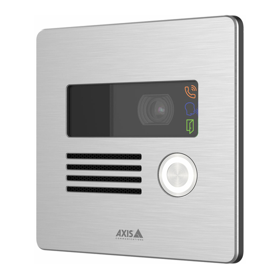
AXIS I8016-LVE Network Video Intercom Product overview Product overview Call indicator icons on page 20 Camera Call button IR illuminator Speaker Microphone I/O connector on page 21 Control button on page 20 Audio connector on page 21 10 Status LED... -
Page 5: Get Started
Get started Find the device on the network To find Axis devices on the network and assign them IP addresses in Windows®, use AXIS IP Utility or AXIS Device Manager. Both applications are free and can be downloaded from axis.com/support. - Page 6 Secure passwords Important Axis devices send the initially set password in clear text over the network. To protect your device after the first login, set up a secure and encrypted HTTPS connection and then change the password. The device password is the primary protection for your data and services. Axis devices do not impose a password policy as they may be used in various types of installations.
-
Page 7: Configure Your Device
AXIS I8016-LVE Network Video Intercom Configure your device Configure your device This section will cover all the important configurations that an installer needs to do to get the product up and running after the hardware installation has been completed. Set up direct SIP (P2P) VoIP (Voice over IP) is a group of technologies that enables voice and multimedia communication over IP networks. -
Page 8: Create A Contact
AXIS I8016-LVE Network Video Intercom Configure your device In this device, VoIP is enabled through the SIP protocol. For more information about SIP, see Session Initiation Protocol (SIP) on page 11 There are two types of setups for SIP. A PBX server is one of them. Use a PBX server when the communication should be between an infinite number of user agents within and outside the IP network. -
Page 9: Configure The Call Button
By default, the call button is configured to make VMS (Video Management System) calls. If you want to keep this configuration, you just need to add the Axis intercom to the VMS. This example explains how to set up the system to call a contact in the contact list when a visitor presses the call button. -
Page 10: Benefit From Ir Light In Low-Light Conditions By Using Night Mode
AXIS I8016-LVE Network Video Intercom Configure your device Go to System > Events > Rules and add a rule. In the Name field, enter "DTMF unlock door". From the list of conditions, under Call, select DTMF and Unlock door. From the list of actions, under I/O, select Toggle I/O once. -
Page 11: Learn More
In the Axis product, VoIP is enabled through the Session Initiation Protocol (SIP) and Dual-Tone Multi-Frequency (DTMF) signaling. Example When you press the call button on an Axis intercom, a call is initiated to one or more predefined recipients. When a recipient replies, a call is established. The voice and video is transferred through VoIP technologies. - Page 12 PBX makes the device accessible as long as it is registered to the PBX. Example sip:mydoor@company.com sip:myspeaker@company.com PBX sip.company.com sip:office@company.com When you press the call button on an Axis intercom, the call is forwarded through one or more PBXs to a SIP address either on the local IP network or over the internet.
-
Page 13: Set Up Rules For Events
To learn more, check out our guide Get started with rules for events. NAT traversal Use NAT (Network Address Translation) traversal when the Axis device is located on an private network (LAN) and you want to access it from outside of that network. -
Page 14: Troubleshooting
5. Use the installation and management software tools to assign an IP address, set the password, and access the device. The installation and management software tools are available from the support pages on axis.com/support. You can also reset parameters to factory default through the device’s webpage. Go to Maintenance > Factory default and click Default. -
Page 15: Technical Issues, Clues, And Solutions
Axis device. Check all cabling and reinstall the device. Possible IP address conflict The static IP address in the Axis device is used before the DHCP server sets a dynamic address. with another device on the... -
Page 16: Performance Considerations
Heavy network utilization due to poor infrastructure affects the bandwidth. • Viewing on poorly performing client computers lowers perceived performance and affects frame rate. • Running multiple AXIS Camera Application Platform (ACAP) applications simultaneously may affect the frame rate and the general performance. Contact support Contact support at axis.com/support. -
Page 17: Connect Equipment
AXIS I8016-LVE Network Video Intercom Connect equipment Connect equipment Relay powered by PoE (12V) 1. To check relay state, go to System > Accessories and find the relay port. 2. Set Normal state to: for a fail-secure lock. for a fail-safe lock. -
Page 18: 12V Fail-Secure Lock Powered By Poe From Intercom
AXIS I8016-LVE Network Video Intercom Connect equipment Potential-free relay 1. To check relay state, go to System > Accessories and find the relay port. 2. Set Normal state to: for a fail-secure lock. for a fail-safe lock. 12V Fail-secure lock powered by PoE from intercom 1. -
Page 19: 12V Fail-Secure Lock Powered By External Power Supply
AXIS I8016-LVE Network Video Intercom Connect equipment 12V Fail-secure lock powered by external power supply 1. To check relay state, go to System > Accessories and find the relay port. 2. Set Normal state to: for a fail-secure lock. for a fail-safe lock. -
Page 20: Specifications
AXIS I8016-LVE Network Video Intercom Specifications Specifications Front panel indicators and controls When you connect the product to power, the indicator icons and the indicator strip light up for a few seconds. Call indicator icons Icon Indication Steady amber when outgoing call initiated. -
Page 21: Connectors
AXIS I8016-LVE Network Video Intercom Specifications Connectors Network connector RJ45 Ethernet connector with Power over Ethernet (PoE). Audio connector 4-pin terminal block for audio input and output. Function Notes Line in Line in (mono) Audio ground Line out Line out (mono) -
Page 22: Hazard Levels
AXIS I8016-LVE Network Video Intercom Safety information Safety information Hazard levels DANGER Indicates a hazardous situation which, if not avoided, will result in death or serious injury. WARNING Indicates a hazardous situation which, if not avoided, could result in death or serious injury. - Page 23 User Manual Ver. M6.4 AXIS I8016-LVE Network Video Intercom Date: February 2022 © Axis Communications AB, 2020 - 2022 Part No. T10154915...
Need help?
Do you have a question about the I8016-LVE and is the answer not in the manual?
Questions and answers