
Subscribe to Our Youtube Channel
Related Manuals for Axis 2N LTE Verso


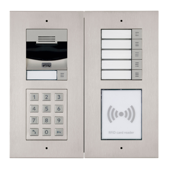
Summary of Contents for Axis 2N LTE Verso
- Page 1 ® 2N LTE Verso Modular LTE Intercom Configuration Manual Firmware: 2.30 Version: 2.30 www.2n.cz...
- Page 2 The 2N TELEKOMUNIKACE a.s. is a Czech manufacturer and supplier of telecommunications equipment. The product family developed by 2N TELEKOMUNIKACE a.s. includes GSM gateways, private branch exchanges (PBX), and door and lift communicators. 2N TELEKOMUNIKACE a.s. has been ranked among the Czech top companies for years and represented a symbol of stability and prosperity on the telecommunications market for almost two decades.
-
Page 3: Table Of Contents
Content: 1. Product Overview 2. Express Wizard for Basic Settings 3. Model Differences and Function Licensing 3.1 Function Licensing 4. Signalling of Operational Statuses 5. Intercom Configuration 5.1 Status 5.2 Directory 5.3 Hardware 5.4 Services 5.5 System 5.6 Used Ports 6. -
Page 4: Product Overview
1. Product Overview 2N LTE door intercoms are a successful substitute for classic Speakerphone bell button panels and complex circuitry of bells and domestic phones where structured cabling cannot be deployed. The intercoms render more sophisticated and extensive services than standard domestic phones. The intercom is easy to install - all you have to do is insert a SIM card, connect a power supply and set necessary parameters via the My2N portal. - Page 5 The following symbols and pictograms are used in the manual: Safety Always abide by this information to prevent persons from injury. Warning Always abide by this information to prevent damage to the device. Caution Important information for system functionality. Useful information for quick and efficient functionality. Note Routines or advice for efficient use of the device.
-
Page 6: Express Wizard For Basic Settings
2. Express Wizard for Basic Settings Device Setting Make sure that your device is properly installed and connected to My2N before logging in to the intercom configuration interface. Log in to My2N at https://my2n.com ® and add your intercom to the Remote Configuration . - Page 7 Remember the new password well or put it down just in case. Because if you forget the password, you will have to reset the intercom to default values (refer to the Installation Manual of your intercom model) and lose all your current configuration changes.
- Page 8 Proxy address – set the SIP Proxy IP address or domain name. Registrar address – set the SIP Registrar IP address or domain name. The SIP Proxy and SIP Registrar addresses are usually identical. Registration enabled – enable intercom registration with the set SIP Registrar. If your SIP server requires authentication of terminal equipment, enter the following parameters: Password –...
- Page 9 You can also use the 2N LTE intercom with one or more IP phones without a SIP server. Use the Direct SIP Call for outgoing calls and enter the called phone SIP address (sip:phone_number@phone_ip_address) instead of the phone number. 2N TELEKOMUNIKACE a.s., www.2n.cz 9/211...
- Page 10 Electric Lock Switching Settings An electric lock can be attached to the 2N LTE intercoms and controlled by a code from the intercom numeric keypad, or a code from the IP phone keypad during a call. Connect the electric lock as instructed in the Installation Manual of your intercom model.
-
Page 11: Model Differences And Function Licensing
3. Model Differences and Function Licensing Here is what you can find in this section: 3.1 Function Licensing 2N TELEKOMUNIKACE a.s., www.2n.cz 11/211... - Page 12 – factory value – licensed function to be purchased additionally – unavailable *) The service availability depends on the mobile provider's network configuration. **) The scrambled keypad function is only available for 2N Access Unit 2.0. 2N TELEKOMUNIKACE a.s., www.2n.cz 12/211...
- Page 13 (refer to the License subsection). The following types of licenses are available: Enhanced Audio (Part No. 9137905, Axis Part No. 01376-001) Enhanced Video (Part No. 9137906, Axis Part No. 01377-001) Enhanced Integration (Part No.
- Page 14 Property Enhanced Enhanced Enhanced Enhanced InformaCast Gold /License Audio Video Integration Security (Profi) User sounds • • Automatic • • audio test Noise • • detection Audio/video ...
- Page 15 Property Enhanced Enhanced Enhanced Enhanced InformaCast Gold /License Audio Video Integration Security (Profi) HTTP API (see • • note below) Automation • • functions E-mail sending • ...
- Page 16 Property Enhanced Enhanced Enhanced Enhanced InformaCast Gold /License Audio Video Integration Security (Profi) Limit • • unsuccessful access attempts Switch • Blocking Scrambled • ...
- Page 17 Note Full HTTP API function is available with the Gold or Enhanced Integration license only. Only Camera API and Switch API are available without this license. Note Extended switch setting options – quick dial button switch activation, switch time profile. How do I get the license? Licenses are generated by 2N according to the particular serial number.
-
Page 18: Signalling Of Operational Statuses
4. Signalling of Operational Statuses 2N LTE intercom generates sounds to signal switching and changes of operational statuses. Each status change is assigned a different type of tone. See the table below for the list of signals. Note Signalling of some of the above mentioned statuses can be modified; refer to the User Sounds subsection. - Page 19 Tone Meaning Profile deactivated This tone signals profile deactivation. This function helps, for example, disable alerting of a user group in an office and routing calls either to a pre- defined phone number (porter's lodge, e.g.) or user mobile phones. Refer to the Profile subsection for the deactivation code settings.
- Page 20 Tone Meaning Call end signalling 2N LTE intercom enables the user to set a call end timeout to avoid call blocking. Press a key on your VoIP phone to extend the call time during this timeout. Connected VoIP phone This short tone signals successful connection between a VoIP phone and 2N LTE intercom 2N TELEKOMUNIKACE a.s., www.2n.cz 20/211...
-
Page 21: Intercom Configuration
5. Intercom Configuration 2N TELEKOMUNIKACE a.s., www.2n.cz 21/211... - Page 22 Start Screen The start screen is an introductory overview screen displayed upon login to the intercom web interface. Use the back arrow in the left-hand upper corner of the following web interface pages to return to this screen anytime. The screen header includes the intercom name (refer to the Display Name parameter in the...
- Page 23 Configuration Menu 2N LTE intercom configuration includes 5 main menus: State Directory Hardware Services System including submenus; see below. Status Device – essentials on the intercom Services – information on active services and their states Licence – current states of licences and available intercom functions Directory Users –...
- Page 24 Audio Test – automatic audio test settings SNMP – SNMP settings System Network – LTE network connection settings, 802.1x, packet capturing Date and Time – real time and time zone settings Licence – licence settings, trial licence activation Certificates – certificate and private key settings Auto provisioning –...
-
Page 25: Status
5.1 Status Status menu provides clear status and other essential information on the intercom. The menu is divided into five tabs: Device Services, Licence, Access Log Events Locate device – optical and acoustic signalling of a device. Note: Optical signalling is possible only if the device is equipped with control backlight (Verso, Base, Vario, Force, Safety and Uni). - Page 26 Factory Certificate Installed – specify the user certificate and private key to validate the intercom right to communicate with the ACS Locate device – optical and acoustic signalling of a device. Optical signalling is ® ® possible only if the device is equipped with control backlight ( IP Verso ®...
- Page 27 Services Services tab displays the status of the network interface and selected services. 2N TELEKOMUNIKACE a.s., www.2n.cz 27/211...
- Page 28 Licence Licence tab displays the list of licensed functions of the intercom including their current availability (on the basis of a valid licence key entered in the System | Licence menu). 2N TELEKOMUNIKACE a.s., www.2n.cz 28/211...
- Page 29 Access Log Access Log tab displays the last 10 records on applied cards. Each record includes the card tapping time, card ID and type and description details (validity, card owner, etc.). 2N TELEKOMUNIKACE a.s., www.2n.cz 29/211...
- Page 30 Events Events tab displays the last 500 logged events. Every event contains time and date, event type and description specifying the event. The events can be filtered by type in a dropdown menu, above the event log. – tlačítko slouží k exportu všech zaznamenaných událostí do CSV souboru. 2N TELEKOMUNIKACE a.s., www.2n.cz 30/211...
- Page 31 Event Description AccessLimited Event generated after 5 unsuccessful user authentication atttempts (card, code, fingerprint). The access module gets blocked for 30 seconds even if the subsequent authetication is correct. AccessTaken Card tapping in Anti-passback area. ApLockStateChanged Change of the emergency lockdown state (on/off). AudioLoopTest Generated after the audio test indicating the test result.
- Page 32 Event Description DtmfPressed DTMF code pressing during a call. DtmfEntered DTMF code receiving during a call. FingerEntered Fingerprint authorisation. FingerEnrollState Finger enrolment on a reader for fingerprint loading. HardwareChanged Change of extending module connection. InputChanged Signals a state change of the logic input. KeyPressed Generated whenever a button is pressed (numeric keypad digits are 0,1,2...,9 and quickdial buttons are %1,%2 ...).
- Page 33 Event Description RegistrationStateChanged Change of the SIP Proxy registration state. RexActivated Event at input activation set for the REX button. SilentAlarm Silent alarm event generated whenever a code higher by one than the correct one is entered. With access code 123, the silent alarm code is 124.
-
Page 34: Directory
5.2 Directory Here is what you can find in this subsection: 5.2.1 Users 5.2.2 Time Profiles 5.2.3 Holidays 2N TELEKOMUNIKACE a.s., www.2n.cz 34/211... - Page 35 5.2.1 Users The Users list is one of the crucial parts of the intercom configuration. It contains user information relevant for such intercom functions as quick dialling, RFID card/code door unlocking, missed call e-mails and so on. The Users list contains up to 1999 users (variable in the 2N LTE intercom models) –...
- Page 36 Having been read, the card ID is compared with the intercom card database. If the card ID matches any of the cards in the database, the appropriate action will be executed: switch activation (door unlocking, etc.). To change the switch number to be activated, use the Associated Switch parameter in the...
- Page 37 Every record in the Users list includes the following parameters: Name – mandatory parameter for easier user search, for example. Photo – load the user photo. Click the photo adding frame to display the Photo editor to load a photo from a file or create a user photo using an integrated camera.
- Page 38 number via the numerical keypad and presses the * key. You are recommended to place a clear user/virtual number list nearby including simple instructions for use to facilitate this type of user calls. Enable this function in the Dial by Numeric Keypad in the Hardware / Keypad...
- Page 39 You can assign up to three user phone numbers to each user position. In case the user is inaccessible on one number, the following number will be dialled after a ringing timeout. Enable the Parallel call to following number to enable dialling multiple numbers simultaneously.
- Page 40 IP Eye address – set the address of the PC to be sent a special UDP message on ® each active user phone number call. With the aid of this message, the 2N IP Eye application displays the camera image screen for those users who are not provided with a display-equipped videophone.
- Page 41 Parallel call to following deputy – enable group calling, i.e. calling to more phone numbers at the same time. You can call the firs two numbers, the last two numbers, ar all of three user numbers in parallel. Once one of the calls is answered, the other calls are automatically terminated.The maximum total count of numbers to be dialled in parallel is 16, which can occur when group calling and multiple numbers assigned to a speed dial button are used simultaneously.
- Page 42 Valid to – set the end of the mode validity term. Each user can be assigned a private switch activation code. The user switch codes can be arbitrarily combined with the universal switch codes defined in the Hardware | Switches menu.
- Page 43 Virtual card ID – set the user virtual card ID for user identification in the devices that are integrated with the 2N IP intercoms via a Wiegand interface. Each user can be assigned just one virtual card. The virtual card ID is a sequence of 6–32 characters: 0–9, A–F.
- Page 44 Pairing state – display the current pairing state (Inactive, Waiting for pairing, PIN validity expired or Paired). Pairing valid until – display the date and time of the generated authorisation PIN validity end. Pairing via Bluetooth Module in Intercom To pair a mobile phone with the user: Click at Auth ID to start pairing for the selected user account.
- Page 45 User Fingerprint Setting Instructions To load fingerprints, use the 2N® LTE Verso (Part No. 9155045) fingerprint reader or an external USB fingerprint scanner (Part No. 9137423E) as follows: ® 1a) To load fingerprints via the LTE Verso reader, use the web interface at the selected user and click Load via fingerprint reader module in Directory / Users/ User fingerprints.
- Page 46 Click to select a finger for fingerprint loading. Up to two fingerprints may be saved for each user. Click SCAN FINGER to load a fingerprint. 2N TELEKOMUNIKACE a.s., www.2n.cz 46/211...
- Page 47 Place the selected finger on an external USB reader. This process is repeated three times for greater precision. Repeat the process if any inconsistency occurs during fingerprint reading. 2N TELEKOMUNIKACE a.s., www.2n.cz 47/211...
- Page 48 If fingerprint scanning is successful, click DONE to confirm the settings. To set the finger function, click the icon to display the list of available functions: Door opening Silent alarm; configurable only if Door opening is active Automation F1 – generate the FingerEntered event in Automation. F1 helps distinguish the applied finger in Automation.
- Page 49 Click SAVE AND QUIT to confirm the fingerprint enrolment and selected functions. You can check the current settings in the User tab. USB RFID Card Reader It is possible to read the card ID via an RFID card reader. Proceed as follows: Go to the 2N USB Driver settings.
- Page 50 Press the Read button via the 2N LTE intercom web interface. Tap the card on the card reader. 2N TELEKOMUNIKACE a.s., www.2n.cz 50/211...
- Page 51 The card ID is successfully read. Do not forget to save the configuration. 2N TELEKOMUNIKACE a.s., www.2n.cz 51/211...
- Page 52 5.2.2 Time Profiles Such intercom functions as outgoing calls and RFID card/numeric code access, for example, can be time-limited by being assigned a time profile . By assigning a time profile you can: block all calls to a selected user beyond the set time interval block calls to selected phone numbers beyond the set time interval block RFID access for a user beyond the set time interval block numeric code access for a user beyond the set time interval...
- Page 53 The time profiles are defined not only using the week time sheet but also manually with the aid of special activation/deactivation codes that you can assign to them after arriving in/before leaving your office, for example. Enter the activation/deactivation codes using the numeric keypad of your intercom or phone (during the intercom call). Refer to the Directory Time Profiles...
- Page 54 If a day is marked as holiday (refer to Directory Holidays ), the last table row (Holiday) is applied regardless of the day in a week. Make sure that the real time settings are correct (refer to the Date and Time subsection) to make this function work properly.
- Page 55 5.2.3 Holidays Here select the bank holidays (including Sundays). You can assign them different time intervals than to working days in their time profiles. You can set holidays for the coming 10 years (click the year number at the top of the screen to select a year).
-
Page 56: Hardware
5.3 Hardware Here is what you can find in this section: 5.3.1 Switches 5.3.2 Door 5.3.3 Audio 5.3.4 Camera 5.3.5 Keypad 5.3.6 Buttons 5.3.7 Backlight 5.3.8 Display 5.3.9 Digital Inputs 5.3.10 Extenders 2N TELEKOMUNIKACE a.s., www.2n.cz 56/211... - Page 57 5.3.1 Switches Switches provide a very flexible and efficient control of such intercom peripherals as electric door locks, lighting, additional ringing signalling, and so on. 2N LTE intercoms allows you to configure up to 4 (depending on model types) independent all-purpose switches.
- Page 58 Caution The options marked with *) require their respective active licences. If a switch is active, you can: activate any logical output of the intercom (relay, power output). ® activate the output to which the IP/LTE Intercom – Security Relay module is connected.
- Page 59 Switch mode – set the monostable/bistable mode for the switch. The switch is switched off after a timeout in the monostable mode and switched on with the first activation and off with the next activation in the bistable mode. Switch-on duration – set the switch-on time for a monostable switch. This value is not applied in the bistable mode.
- Page 60 Note A switch activation value higher than 1 s can be set for the security output type. A value equal to or higher than 0.1 s can be set for the normal inverse output types. The table above includes a list of universal codes that help you activate switches from the phone or intercom keypad.
- Page 61 Activation by call – enable switch activation by an incoming or outgoing call, for example. During an outgoing call the switch is activated after SIP message 180 Ringing is received. The called party confirms ringing by this message. The switch is active during the whole call in the bistable mode, and activated by the call beginning and deactivated after the predefined switch-on duration in the monostable mode.
- Page 62 Command sent upon activation – set the command to be sent to the external device (WEB relay, e.g.) upon switch activation. The command is sent via the HTTP (GET request) and must be as follows: http://ip_address/path . E.g.: http://192.168.1.50/relay1=on Command sent upon deactivation – set the command to be sent to the external device (WEB relay, e.g.) upon switch deactivation.
- Page 63 With an external relay, Part No. 9137410E , the following HTTP commands are used: To turn on the switch – http://ip_address/state.xml?relayState=1 (e.g.: http://192.168.1.10/state.xml?relayState=1 To turn on for pre-defined time (default value is 1.5 s) – http://ip_address /state.xml?relayState=2 (e.g.: http://192.168.1.10/state.xml?relayState=2 To turn off -http://ip_address/state.xml?relayState=0 (e.g.: http://192.168.1.10 /state.xml?relayState=0 With an external relay, Part No.
- Page 64 5.3.2 Door List of Parameters Door Assigned Switch – Select a switch for electromagnetic door lock control. The switch state controls the door unlocking signalling (green door symbol, green LED). 2N TELEKOMUNIKACE a.s., www.2n.cz 64/211...
- Page 65 Assigned Input – Define one (or none) of the logical inputs for open door detection. Unauthorised Door Open Detection – Detect if the door was open when switch has been locked. Door Open Too Long Detection – Door open to long detection. Maximum Door Open Time –...
- Page 66 Username – Authentication user name. Connection state – display the current Synergis server connection state or error state description if necessary. Failure reason – display the failure reason of the last Synergis server connection attempt – the last error response, 404 Not Found, for example. Entry Rules Access Enabled –...
- Page 67 – select one of the pre-defined profiles or set the time profile for the given element manually. Authentication Mode – Set the authentication mode for the time profile in this row including multiple authentication for enhanced security. Select Access denied to ban access. Zonal Code –...
- Page 68 The plus/minus cards are used for user card administration. When a plus card is tapped on the card reader, any other tapped card is added to the Directory list as a new user with an access card assigned. The user !Visitor #card_ID is automatically created in the device.
- Page 69 Exit Rules Access Enabled – Enable access in a direction (entry, exit). If access is disabled, the door cannot be opened from the selected side. Emergency Lockdown – display the active emergency door lock setting: Unlocked/Locked. Caution Emergency lockdown is superior to all time and access profiles. Time profile –...
- Page 70 Caution If the time profile is unset, the authentication mode is ignored on the given row. Zonal Code – Enter the switch numeric zonal code consisting of two character at least. However, four characters at least are recommended. Authentication Signalling – select how to signal that a card or another identifier has been read.
- Page 71 The plus/minus cards are used for user card administration. When a plus card is tapped on the card reader, any other tapped card is added to the Directory list as a new user with an access card assigned. The user !Visitor #card_ID is automatically created in the device.
- Page 72 5.3.3 Audio All the 2N LTE intercom models are equipped with a speaker or power amplifier output to which an external loudspeaker can be connected. Set the phone call and state signalling volume control in this configurat ion section. Set the Master volume control the master volume of the device: volum e of calls, signalling tones, etc.
- Page 73 Master volume – set the master volume for the entire system. This setting affects the volume of phone calls and all signalling tones. Adaptive volume – enable the adaptive volume mode in which the speaker volume is adjusted automatically depending on the noise level of the intercom installation site.
- Page 74 Key beep volume – set the key beep volume. The volume values are relative against the set master volume. Warning tone volume – set the volume of warning and signalling tones described in the Signalling of Operational Statuses section. The volume values are relative against the set master volume.
- Page 75 Switch on automatic detection of noise or microphone noise level threshold exceeding. Process the threshold exceeding alarm using Event.NoiseDetected and assign it to other user actions. Noise Level Threshold – set the microphone noise level threshold for alarm setting. Alarm Start Delay – set the time interval during which the signal must be above the threshold to start alarm.
- Page 76 5.3.4 Camera This menu is only available in the 2N LTE intercom models that are equipped with an internal camera or can be connected to an external camera. The camera signal can be streamed directly into the call via a videophone, sent by E-mail, streamed via ONVIF /RTSP to another device (a video surveillance device, e.g.), or simply HTTP downloaded from the intercom in the JPEG format.
- Page 77 List of Parameters Common Settings Default video source – set the default video signal source. Choose Internal camera (or an analogue camera connected to the intercom) or External IP camera. The change of the default video signal source is applied to the RTSP ®...
- Page 78 Live Preview – display a live preview from a 2N IP intercom camera. Internal Camera Brightness level – set the camera image brightness level. Colour saturation – set the camera image colour saturation. Camera mode – select suitable camera modes according to the current intercom installation conditions (indoor/outdoor use).
- Page 79 Motion detection enabled – enable automatic motion detection via an internal camera. Motion is detected by monitoring of a brightness change in the selected image section in time. When objects move within the camera range, the selected part of the image detects an activity, which can be expressed in percentage. If the activity exceeds the upper limit, motion is detected and indicated as long as the activity drops below the lower limit.
- Page 80 External Camera External camera enabled – enable RTSP stream download from the external IP camera. Complete the valid RTSP stream address or the username and password to make the function work properly. RTSP stream address – enter the IP camera RTSP stream address: rtsp://camera_ip_address/parameters .
- Page 81 The Camera Preview window displays the current image received from an external camera. If the external camera is disconnected or configured incorrectly, the N/A characters are displayed on a blue background. The External IP Camera Log displays the RTSP communication with the selected external IP camera including failures and error states if any.
- Page 82 5.3.5 Keypad This configuration section helps you set the numeric keypad and quick dial button functions. 2N LTE intercoms allows you to: use the numeric keypad for dialling virtual phone numbers use the numeric keypad for dialling a user position use the numeric keypad for entering the access code for door unlocking, e.g.
- Page 83 List of Parameters Basic Settings Dial User Virtual Number by Numeric Keypad – enable user calling via the numeric keypad by entering the user virtual number and pressing *. Telephone mode enabled – enable call setup to phone numbers dialled via the intercom numerical keypad.
- Page 84 5.3.6 Buttons Assign the Directory / Users users to the quick dial buttons. By default, all available intercom buttons are assigned to the listed users. A non-assigned button can be used for automation or switch activation, for example. Button function during call – set the quick dial button function during a call. You can only set the button that initiated the call.
- Page 85 None – button pressing does not affect the call setup or active call. Hang up – button pressing terminates the call setup or active call. Dial the following – button pressing initiates dialling of the following user number in the users list. This accelerates the dialling process in case the user is inaccessible on some of its phone numbers.
- Page 86 Display the list of all potentially available intercom buttons including those physically ® absent. In some IP Verso models , the button list is divided into 8/5-item groups corresponding to the button extending modules. Click , select the user and press Add to add a user to the editing field.
- Page 87 5.3.7 Backlight This tab helps you control the backlight level of nametags, buttons and brightness of signalling LEDs. If equipped with an ambient light level sensor, the intercom automatically chooses the suitable backlight level within the set range of values. The selected intercoms allow you to control the backlight brightness of name tags (buttons) and signalling LEDs (illuminated pictograms).
- Page 88 Property/Model ® LTE Verso Backlight level control Ambient light level sensor Independent name tag and LED backlight level control Intensity by day – set the LED intensity percentage value for the day mode. ntensity by night – set the LED intensity percentage value for the night mode the Intensity by day and Intensity by night are set to one and the same value,...
- Page 89 5.3.8 Display ® Some intercom models LTE Verso can be equipped with a colour LCD display. The device state is displayed (call progress, door opening, etc.) and the following modes are available: ® Displej – enable the display and language settings for LTE Verso.
- Page 90 List of Parameters Display for 2N ® LTE Verso Basic Settings Phone book displayed – enable/disable display of the phone book function. Entry Keypad – enable the keypad/keypad type. Disabled – disable the keypad. Regular keypad – set the regular keypad type. Scramble keypad –...
- Page 91 User Localization Original language – download the localisation file template for own translation. It is an XML file with all the texts to be displayed. Custom language – remove, download and upload a localisation file of your own. Note If none of the pre-defined languages is convenient for you, proceed as follows: Download the original language file (English).
- Page 92 Phonebook This tab helps you configure a structured user list to be displayed. Create any count of groups and add any count of phonebook users to groups. No user can be assigned more times to a group, but one user can be added to multiple groups at the same time.
- Page 93 The groups and users are displayed as added to the phonebook. Click to assign a priority. The group/user with the last-assigned priority is always displayed on the top of the list. Groups are superior to users in the list. Caution Remember to save the phonebook changes.
- Page 94 ® Make sure that the image resolution is 214 x 214 pixels for LTE Verso . Other sizes will be adjusted to the display resolution automatically. Click the magnifier icon to view the loaded image, press to delete an image and click to hide a selected image/video on the device display.
- Page 95 5.3.9 Digital Inputs In this configuration section set the parameters associated with digital inputs and their interconnections with other intercom functions. List of Parameters Assigned input – define one (or none) of the logical inputs for secured state detection. The secured state is then signalled by a LED on the intercom, whose location may vary in different intercom types.
- Page 96 Note Secured state signalling is typically used with a access control controller connected to one of the intercom digital inputs. The wire leading from the PBX is connected to the intercom directly or via an extending module. The secured state LED location is variable depending on the i n t e r c o m t y p e : ®...
- Page 97 5.3.10 Extenders ® LTE Verso intercoms can be enhanced with extending modules connected to the intercom basic unit. The following modules are available: Five-button module Keypad module Infopanel module Card reader module Bluetooth module I/O module Wiegand module Inductive loop module Display module Fingerprint reader Touch keypad...
- Page 98 You can configure each module separately. The parameters are specific for the given module type . Note The extending modules are displayed in the order corresponding to their interconnection. The modules connected further from the basic unit are listed below. If more modules of the same type are connected to one intercom, it may be difficult to assign a setting to a particular module.
- Page 99 Main Unit Module Configuration Output 1 maximum power – set the maximum load to be connected to the power output available on the basic unit. When the output is active, the consumption of the other modules (backlight level, etc.) can be adjusted automatically in order that the maximum allowed consumption of the intercom cannot be exceeded.
- Page 100 Keypad Module Configuration Module Name – set the module name for logging events from the keypad. Door – set the reader direction (Door Entry, Door Exit) for the Attendance system purposes. Forward to Wiegand Output – set a group of Wiegand outputs to which all pressed keys are to be forwarded.
- Page 101 125 kHz Card Reader Module Configuration Module Name – set the module name for card reader logging purposes. Door – set the reader direction (Door Entry, Door Exit) for the Attendance system purposes. Associated Switch – set the switch to be activated after user authentication via this module.
- Page 102 13.56 MHz Card Reader Module Configuration Module Name – set the module name for card reader logging purposes. Door – set the reader direction (Door Entry, Door Exit) for the Attendance system purposes. Associated Switch – set the switch to be activated after user authentication via this module.
- Page 103 Bluetooth Module Module name – set the module name for logging events from the Bluetooth module. Direction – set the reader direction (Not specified, Arrival, Departure) for the Attendance system purposes. Multiple authentication – enable multiple user authentication via this module (or, authentication is controlled by the user card settings;...
- Page 104 Middle – less than 2 m for most phones Long – maximum possible range Operation mode – set the authentication method for a mobile phone: Tap in app – authentication has to be confirmed by tapping on an icon in the application running in a mobile phone.
- Page 105 connect the intercom to the security system in your building, for example (to send IDs of the RFID cards tapped on the RFID reader or codes received on any Wiegand ® input). The Wiegand Isolator is also equipped with one logical input and one logical output, which can be controlled via Automation Module Name –...
- Page 106 Change Facility Code – set the first code part via Wiegand. This applies to Wiegand OUT for 26-bit code format. Contact your security system supplier to know if the Facility Code is requested. Facility Code – define the 2N IP device location in the security system. Enter a decimal value for the location (0–255).
- Page 107 Display Module Configuration Module Name – set the module name for input/output specification in the SetOutput, GetInput and InputChanged objects in the 2N Automation Door – set the reader direction (Arrival, Departure) for the Attendance system purposes. 2N TELEKOMUNIKACE a.s., www.2n.cz 107/211...
- Page 108 Fingerprint Reader Module Configuration Module Name – set the module name for logging events from the Fingerprint reader. Door – set the reader direction (Arrival, Departure) for the Attendance system purposes. Associated Switch – set the switch to be activated after user authentication via this module.
- Page 109 Touch Keypad Module Name – set the module name for logging events from the keypad. Door – set the reader direction (Door Entry, Door Exit) for the Attendance system purposes. Blink at Keystroke – set keystroke light signalling for noisy environments where acoustic signals are difficult to hear.
- Page 110 Touch keypad & RFID reader 125 kHz, 13.56 MHz 13.56 MHz (125 kHz) Card Reader (serial number) Module Name – set the module name for card reader logging purposes. Door – set the reader direction (Not specified, Arrival, Departure) for the Attendance system purposes.
- Page 111 Allowed Card Types – set the type of a card to be accepted by the card reader. The card reader supports just one card type at an instant. Samsung NFC Compatibility – enable NFC compatibility with the Samsung phones. Forward to Wiegand Output – set a group of Wiegand outputs to which all the received RFID card IDs will be resent.
- Page 112 Bluetooth & RFID reader 125 kHz, 13.56 MHz 13.56 MHz (125 kHz) Card Reader (serial number) Module Name – set the module name for card reader logging purposes. Door – set the reader direction (Not specified, Arrival, Departure) for the Attendance system purposes.
- Page 113 Allowed Card Types – set the type of a card to be accepted by the card reader. The card reader supports just one card type at an instant. Samsung NFC Compatibility – enable NFC compatibility with the Samsung phones. Forward to Wiegand Output – set a group of Wiegand outputs to which all the received RFID card IDs will be resent.
-
Page 114: Services
5.4 Services Here is what you can find in this section: 5.4.1 Phone 5.4.2 Streaming 5.4.3 ONVIF 5.4.4 E-Mail 5.4.5 Mobile Key 5.4.6 Automation 5.4.7 HTTP API 5.4.8 User Sounds 5.4.9 Web Server 5.4.10 Audio Test 5.4.11 SNMP 2N TELEKOMUNIKACE a.s., www.2n.cz 114/211... - Page 115 5.4.1 Phone The Phone service is one of the basic functions of the intercom: helps you establish connections with other IP network terminal equipment. The 2N LTE intercoms support the extended SIP and are compatible with and certified by the leading SIP PBX and terminal equipment manufacturers (CISCO, Avaya, Broadsoft, etc.).
- Page 116 Explanation of IP Telephony Terms (Session Initiation Protocol) – is a phone call signalling transmission protocol used in IP telephony. It is primarily used for setting up, terminating and forwarding calls between two SIP devices (the intercom and another IP phone in this case).
- Page 117 equivalently. Outgoing calls are primarily processed by account 1, or, if account 1 is not registered (due to SIP exchange error, e.g.), by account 2. Select the account number for the phone numbers included in the phone directory to specify the account to be used for outgoing calls (example: 2568/1 - calls to number 2568 go via account 1, sip: 1234@192.168.1.1 calls to sip uri via account 2).
- Page 118 Use authentication ID – enable the use of an alternative ID for intercom authentication. If disabled, the phone number defined above is used for authentication. Authentication ID – enter the alternative ID for authentication. Password – enter the password for authentication. The parameter is applied on if your PBX requires authentication.
- Page 119 Registrar address – set the SIP Registrar IP address or domain name. Registrar port – set the SIP Registrar port (typically 5060). Backup registrar address – set the SIP registrar IP address or domain name to be used where the main registrar fails to respond to requests. Backup registrar port –...
- Page 120 SIP transport protocol – set the SIP communication protocol: UDP (default), TCP or TLS. Minimum Allowed TLS Version – define the lowest TLS version to be connected to the devices. Trusted certificate – specify one of the three sets of certificates issued by certification authorities to verify the SIP server public certificate validity, refer to the Certificates subsection.
- Page 121 RTP timeout – set the audio stream RTP packet receiving timeout during a call. If this limit is exceeded (RTP packets are not delivered), the call is terminated by the intercom. Set the parameter to 0 to disable this function. The parameter is only set for account 1 but applies to both the SIP accounts.
- Page 122 Manual – the intercom alerts incoming calls and the user answers them using a numeric keypad button, and Automatic – the intercom answers incoming calls automatically. You can set the call receiving mode for each SIP account separately. Automatic (DTMF only) – the intercom answers incoming calls automatically only if DTMF without connection to a microphone and speaker is received.
- Page 123 Crestron Multicast Address – set the multicast address to be used for multicast video for Crestron devices. Crestron Multicast Port – set the multicast port to be used for multicast video for Crestron devices. Crestron Multicast TTL – set the Time To Live (TTL) value to be used for sending video early media for Crestron devices.
- Page 124 SIP INFO (RFC-2976) – enable DTMF sending via SIP INFO messages according to RFC-2976. The tab below helps you define how DTMF characters shall be received from the intercom. Check the DTMF receiving options and settings of the opponent to make the function work properly.
- Page 125 Video Enable/disable the use of video codecs for call setups and set their priorities. Video resolution – set the video resolution for phone calls. Video framerate – set the video frame rate for phone calls. Video bitrate – set the video stream bit rate for phone calls. QoS DSCP value –...
- Page 126 H.264 payload type (1) – set the payload type for video codec H.264 (packetisation mode 1). Set a value from the range of 96 through 127, or 0 to disable this codec type. H.264 payload type (2) – set the payload type for video codec H.264 (packetisation mode 2).
- Page 127 Device ID – set the device ID to be displayed in the LAN device list in all the 2N devices in one and the same LAN. You can direct a call to this device by setting the user phone number as device:device_ID in these devices. Access Key 1-3 –...
- Page 128 LAN Device Count – display the current count of local 2N answering units connected to the intercom, i.e. those registered with the intercom. Number of Listening/Watching Devices – display the current count of 2N answering units watching video streams from the intercom. Show LAN device list –...
- Page 129 5.4.2 Streaming 2N LTE intercoms provide several audio/video streaming methods; refer to the table below: Transmission Description method JPEG/HTTP Static JPEG image transmission. Refer to the JPEG tab below. MJPEG A series of consecutive JPEG images, the Server Push - multipart/x-mixed- /HTTP replace method.
- Page 130 Transmission Description method RTP/UDP- Uncontrolled RTP packet multicast. Supported for audio (G.711) only. Refer to the Multicast Multicast tab below. Explanation of Terms RTP (Real-Time Transport Protocol) – is a protocol defining the standard packet format for audio/video transmission via IP networks. 2N LTE intercom employs this protocol for audio/video streaming.
- Page 131 List of Parameters RTSP 2N LTE intercoms integrate an RTSP server, which can be configured in this tab. The RTSP server allows for audio/video streaming. You can choose the data transmission method, video compression method/parameters and other parameters associated with transmission security and quality. Enter the following RTSP Uri for connection to the intercom RTSP server: rtsp://intercom_ip_address/ Set the video stream (video codec type, image resolution, frame rate and bit rate)
- Page 132 Anonymous Access – enables access to the RTSP server without user authentication. If this field is unselected, the RTSP client must authenticate itself as one of the ONVIF users while accessing the server; refer to Account setting in the Services / ONVIF subsection. Stream URL –...
- Page 133 IP address 1–4 – set up to 4 authorised IP addresses from which you can log in to the RTSP server. If none of the four fields is completed, any IP address can be used for login. QoS DSCP value – set the audio/video RTP packet priority in the network. The set value is sent in the TOS (Type of Service) field in the IP packet header.
- Page 134 JPEG Here configure the simplest way of video streaming: JPEG/HTTP and MJPEG/HTTP. Send the following GET address query to download images from the intercom: http://intercom_ip_address/api/camera/snapshot?width=W&height=H or (for MJPEG, HTTP Server Push): http://intercom_ip_address/api/camera/snapshot?width=W&height= &fps= where specify image resolution (supported resolutions: 160 x 120, 320 x 240, 640 x 480, 176 x 144, 322 x 272, 352 x 288, 1280 x 960 –...
- Page 135 Some IP phones (SNOM 820/870) do not support video calls but are able to download and display JGEG snapshots from the predefined IP address during a call. 2N LTE intercoms do support this function: set the parameters in this tab. JPEG video activated by call –...
- Page 136 Multicast sender enabled – enable RTP packet sending to the selected multicast address and port. Send to address – set the destination multicast IP address for the audio stream. Send to port – set the destination port for the audio stream. Codec–...
- Page 137 Broadcast enabled– enable the Broadcast command to set up an audio stream sent from the Informacast server to the intercom. Capture enabled– enable the Capture command to set up an audio stream sent from the intercom to the Informacast server. Listen enabled–...
- Page 138 Password – set a password for the above mentioned FTP server user. Passive mode – select the passive transmission mode (as web browser). Remote dir ectory – set the FTP server directory to which the camera images shall be saved. Picture resolution –...
- Page 139 Click Apply & Test to save the current FTP server configuration, load the camera image and save the image to the FTP server. The window above displays the FTP server communication details during saving. Angelcam Angelcam Client Enabled – enable the Angelcam Client function. UUID –...
- Page 140 Tamper Switch Activation – the video stream to the Angelcam cloud storage will start at a tamper switch activation. Motion Detection – the video stream to the Angelcam cloud storage will start whenever motion is detected. Noise Detection – the video stream to the Angelcam cloud storage will start whenever noise is detected.
- Page 141 (ONVIF clients) to discover compatible LAN devices. Enable this function to use a device as an ONVIF compatible one. Calls to Axis Camera Station – povoluje kompatibilitu s VMS systémem Axis Camera Station, který nativně podporuje 2N IP interkomy jako kamery třetích stran.
- Page 142 Be sure to set one user account at least and the proper access level (according to ONVIF specification and used VMS) to achieve full ONVIF functionality . Without this, the basic functionality is only available. Enabled – e nable/disable the user account. Name –...
- Page 143 Note Preset authorisation for ONVIF Username: admin Password: 2n 2N TELEKOMUNIKACE a.s., www.2n.cz 143/211...
- Page 144 5.4.4 E-Mail To inform the intercom users on all missed and/or successfully completed calls, configure the 2N IP intercom to send an e-mail after every call to the called user. You can compile the e-mail subject and message text of your own. If your intercom is equipped with a camera, you can automatically attach one or more snapshots taken during the call or ringing.
- Page 145 List of Parameters SMTP SMTP Service Enabled – enable/disable sending e-mails from the intercom. Server Address – set the SMTP server address to which e-mails shall be sent. Server Port – specify the SMTP server port. Modify the value only if the SMTP server setting is substandard.
- Page 146 Deliver In – set the time limit for delivering an e-mail to an inaccessible SMTP server. Click Apply & Test to send a testing e-mail to the defined address with the aim to test the functionality of the current e-mail sending setting. Enter the destination e-mail address into the Test e-mail address field and press the button.
- Page 147 E-Mail on Call Set e-mail sending during outgoing calls on this tab. Send E-Mail to User at – set e-mail sending in the event of an accomplished / missed outoging call. The e-mail is sent when the connection is terminated. The following options are available: Do Not Send E-mail –...
- Page 148 Body – edit the text to be sent. Use the HTML formatting marks in the text. You can insert special symbols substituting the username, date and time, intercom identification or called number, which will be replaced with the actual value before sending.
- Page 149 Default To – the intercom sends messages to the e-mail address specified for the user when a valid user card is applied. When an invalid card is applied or no e- mail address is assigned to the user, the message shall be sent the e-mail address included here.
- Page 150 Attach Snapshots – enable sending of an attachment including one or more camera snapshots taken during ringing or calling. Snapshot Resolution – set the snapshot resolution for the images to be sent. E-Mail on Event Set that an e-mail shall be sent whenever the SIP gets lost, the device is rebooted or the tamper switch is activated on the device.
- Page 151 SIP Registration Lost Message – set the message to be sent to the specified e-mail address whenever the SIP registration gets lost. Subject – set the e-mail subject to be sent. E-Mail Body – edit the text to be sent. Use the HTML formatting marks in the text.
- Page 152 Subject – set the e-mail subject to be sent. E-Mail Body – edit the text to be sent. Use the HTML formatting marks in the text. You can insert special symbols substituting the username, date & time and device ID. These symbols will be replaced with the actual value before sending. See the list of placeholders below: $User$ Called username $DateTime$ Current date and time...
- Page 153 Count of Snapshots to Be Attached – set the count of snapshots to be attached to the e-mail message. Snapshot Resolution – set the snapshot resolution for the images to be sent. 2N TELEKOMUNIKACE a.s., www.2n.cz 153/211...
- Page 154 5.4.5 Mobile Key 2N LTE intercoms equipped with the Bluetooth module allow for user ® authentication via the Mobile Key application available to devices with iOS 8.1 and higher (iPhone 4s and higher phones) or Android 4.4 KitKat and higher (Bluetooth 4.0 Smart supporting phones).
- Page 155 Encryption Keys and Locations ® ® Mobile Key – intercom communication is always encrypted. Mobile Key cannot authenticate a user without knowing the encryption key. The primary encryption key is automatically generated upon the intercom first launch and can be re-generated manually any time later.
- Page 156 Encryption Key Administration The intercom can keep up to 4 valid encryption keys: 1 primary and up to 3 secondary ones. A mobile device can use any of the 4 keys for communication encryption. The encryption keys are fully controlled by the system administrator. It is recommended that the encryption keys should be periodically updated for security reasons, especially in the event of a mobile device loss or intercom configuration leak.
- Page 157 Restore primary key – by generating a new primary encryption key you delete ® the oldest secondary key. Thus, the Mobile Key users that still use this key will not be able to authenticate themselves unless they have updated the encryption keys in their mobile devices before deletion.
- Page 158 In the case of loss of a mobile phone with access data proceed as follows: Delete the Mobile Key Auth ID value for the user to block the lost phone and avoid misuse. Re-generate the primary encryption key (optionally) to avoid misuse of the encryption key stored in the mobile device.
- Page 159 5.4.6 Automation 2N LTE intercom provides highly flexible setting options to satisfy variable user needs. There are situations in which the standard configuration settings (switch or call modes, e.g.) are insufficient and so 2N LTE intercom offers Automation , a special programmable interface for applications that require complex interconnections with third party systems.
- Page 160 5.4.7 HTTP API HTTP API is an application interface designed for control of selected 2N LTE intercom functions via the HTTP . It enables 2N LTE intercoms to be integrated easily with third party products, such as home automation, security and monitoring systems, etc. HTTP API provides the following services: System API –...
- Page 161 Set authentication methods for the requests to be sent to the intercom for each service. If the required authentication is not executed, the request will be rejected. Requests are authenticated via a standard authentication protocol described in RFC- 2617 . The following three authentication methods are available: None –...
- Page 162 5.4.8 User Sounds 2N LTE intercoms provide standard signalling of operational statuses by tone sequences; refer to the Signalling of Operational Statuses subsection. This function is available with the Gold or Enhanced licence only. If you find the standard sound signalling inconvenient, modify the sounds for the following statuses: Ringing before answering call Ringback tone...
- Page 163 Frequency Bits for sample Sound length Quality 8 kHz 16 bit up to 16 s 3 (not recommended combination) 8 kHz 8 bit up to 32 s 4 low You can also play the recorded files via Automation using the Action.PlayUserSound and, optionally, with the aid of the intercom speaker and/or directly into the phone call.
- Page 164 Invalid input signalling – set the sound to be played when an invalid code in entered (switch/user/profile activation). Invalid position signalling – set the sound to be played when a quick dial button is pressed but the corresponding user position is not programmed. Switch activation signalling –...
- Page 165 You can set days in a week on which the sound shall be played. Click the required day time axis point to add sound playing. While adding, set the exact time, select the user sound and adjust the sound volume. The...
- Page 166 Scheduler enabled – activate playing of preset user sounds as scheduled. 2N TELEKOMUNIKACE a.s., www.2n.cz 166/211...
- Page 167 Refer https://wiki.2n.cz/hip/inte/latest/en/10-media-applications /audacity for user sound creating details. Note The sound recording function is unavailable in the browsers that do not support the WebRTC standard (Internet Explorer, e.g.). 2N TELEKOMUNIKACE a.s., www.2n.cz 167/211...
- Page 168 5.4.9 Web Server You can configure your 2N LTE intercom using a standard browser which accesses the integrated web server. Use the secured HTTPS protocol for communication between the browser and intercom. Having accessed the intercom, enter the login name and password.
- Page 169 List of Parameters Device name – set the device name to be displayed in the right upper corner of ® the web interface, login window and other applications if available (2N Network Scanner, etc). Web interface language – set the default language for administration web server login.
- Page 170 Original language – download the original file containing all the user interface texts in English. The file format is XML; see below. User language – record, load and remove, if necessary, a user file containing your own user interface text translations. <?xml version="1.0"...
- Page 171 5.4.10 Audio Test 2N LTE intercoms allow you to perform periodical tests of the integrated speaker and microphone. For the test purpose, the integrated speaker generates one or more short beeps. The integrated microphone receives the generated tone and the test is successful if the tone is detected correctly.
- Page 172 List of Parameters Audio test enabled – enable automatic execution of the audio test. Test period – set the test period: daily or weekly. Test start time – set the test starting time in the HH:MM format. We recommend you to set a time at which a low intercom traffic is expected. Save and run –...
- Page 173 5.4.11 SNMP 2N LTE intercoms integrate a remote intercom supervision functionality via the SNMP. The integrated SNMP agent becomes available when the Enhanced Integration licence key is added. The intercoms support the SNMP version 2c. List of Parameters Community string – text string representing the access key to the MIB table objects.
- Page 174 Contact – enter the device manager contact (name, e-mail, etc.). Name – enter the device name. Location – enter the device location (1st floor, e.g.). IP address– enter up to 4 valid IP addresses for SNMP agent access to block access from other addresses.
-
Page 175: System
5.5 System Here is what you can find in this section: 5.5.1 Network 5.5.2 Date and Time 5.5.3 Licence 5.5.4 Certificates 5.5.5 Auto Provisioning 5.5.6 Syslog 5.5.7 Maintenance 2N TELEKOMUNIKACE a.s., www.2n.cz 175/211... - Page 176 5.5.1 Network 2N LTE intercom gets connected to the LTE network via a SIM card. The access data (APN, access name and password) are configured automatically. To change the LTE access data configuration, use SMS (refer to the Installation manual) or the LTE tab of the web configuration interface (see below).
- Page 177 Link signalling – Enable signalling of subsequent network connection state changes. If this signalling is disabled, only the first change until the connected state is signalled acoustically. Unselect this only if acoustic signalling were a problem. Verify the network address accessibility –...
- Page 178 HTTP Server – enable the web server availability in the public Internet. RTSP Server – enable the RTSP server availability in the public Internet. SIP – enable the SIP TCP server availability in the public Internet. Modem State – value 9 – connected to the data network. Modem Manufacturer –...
- Page 179 Excellent >= -80 Good >= -90 Fair >= -100 Weak < -100 IP Address – IP address assigned by the provider's mobile network (typically non-public and unavailable from the public Internet). Primary DNS – primary DNS address for translation of domain names to IP addresses.
- Page 180 Trusted Certificate – specify a set of certificates issued by certification authorities to verify the OpenVPN server public certificate validity. Choose one of three certificate sets, see the Certificates subsection. If no certificate issued by a certification authority is specified, the OpenVPN server public certificate is not validated.
- Page 181 2N TELEKOMUNIKACE a.s., www.2n.cz 181/211...
- Page 182 5.5.2 Date and Time If you control validity of phone numbers, lock activation codes and similar by time profiles, make sure that the intercom internal date and time are set correctly. Most 2N LTE intercom models are equipped with a back-up real-time clock to withstand up to several days' long power outages.
- Page 183 List of Parameters Synchronise – push the button to synchronise the intercom time value with your PC time value. Time zone – set the time zone for the installation site to define time shifts and winter/summer time transitions. Time zone rule – if the intercom is installed on a site that it not included in the Time zone parameter, set the time zone rule manually.
- Page 184 5.5.3 Licence Some 2N LTE intercom functions are available with a valid licence key only. Refer to Model Differences and Function Licensing subsection for the list of intercom licensing options. List of Parameters Serial Number – display the serial number of the device for which the licence is valid.
- Page 185 Enhanced security – check whether the functions activated by the Enhanced Security licence are available. Enhanced audio – check whether the functions activated by the Enhanced Audio licence are available. Enhanced video – check whether the functions activated by the Enhanced Video licence are available.
- Page 186 Caution The SW reset does not delete the license key and result in the device restart. If disabled before the SW reset, the automatic license update is enabled automatically and a query is sent to the license server. If the automatic license update is enabled, the query to the license server is sent as planned.
- Page 187 5.5.4 Certificates Some 2N LTE intercom network services use the Transaction Layer Security (TLS) protocol for communication with other LAN devices to prevent third parties from monitoring and/or modifying the communication contents. Unilateral or bilateral authentication based on certificates and private keys is needed for establishing connections via TLS.
- Page 188 Note If you use the Self Signed certificate for encryption of the intercom web server – browser communication, the communication is secure, but the browser will warn you that it is unable to verify the intercom certificate validity. Refer to the tables below for the current list of trusted and user certificates: Press to load a certificate saved on your PC.
- Page 189 Caution It is possible that certificate with private RSA key longer than 2048 bits will be rejected and following message will be displayed: Private key file or private key password was not accepted by device ! For certificates based on elliptic curves use the secp256r1 (aka prime256v1 aka NIST P-256) and secp384r1 (aka NIST P-384) curves only.
- Page 190 5.5.5 Auto Provisioning 2N LTE intercoms help you update firmware and configuration manually, or automatically from a storage on a TFTP/HTTP server selected by you according to predefined rules. You can configure the TFTP and HTTP server address manually. The 2N LTE intercoms support automatic identification of the local DHCP server address (Option 66).
- Page 191 Example: ® LTE Verso with MAC address 00-87-12-AA-00-11 downloads the following files from the TFTP server: hipve-firmware.bin hipve-common.xml hipve-00-87-12-aa-00-11.xml List of Parameters Firmware update enabled – enable automatic firmware/configuration updating from the TFTP/HTTP server. Address retrieval mode – select whether the TFTP/HTTP server address shall be entered manually or a value retrieved automatically from the DHCP server using Option 66 shall be used.
- Page 192 Use authenticatio n – enable authentication for HTTP server access. Username – enter the user name for server authentication. Password – enter the password for server authentication. Trusted Certificate – set the set of CA certificates for validation of the ACS public certificate.
- Page 193 Result Description Unsupported The protocol is not supported. HTTP(s) and TFTP are supported only. protocol Invalid file path The provisioning file location is invalid. DHCP option 66 The server address loading via DHCP Option 66 or 150 has failed. failed Invalid domain The server domain name is invalid due to wrong configuration or name...
- Page 194 Firmware update enabled – enable automatic firmware/configuration updating from the TFTP/HTTP server. Address Retrieval Mode – select whether the TFTP/HTTP server address shall be entered manually or a value retrieved automatically from the DHCP server using Option 66 shall be used. Server Address –...
- Page 195 Info The intercom contains the Factory Cert, a signed certificate used for British Telecom integration, for example. At Boot Time – enable check and, if possible, update execution upon every intercom start. Update Period – set the update period. Set an automatic update to take place hourly/daily/weekly/monthly, or set the period manually.
- Page 196 Update Result (Private Config) – private configuration follows the common configuration update. The device with private configuration is identified by its MAC address. The following options are available: DHCP option 66 failed, Firmware is up to date, Server connection failed, Running..., File not found. Communication Result Detail (Private Config) –...
- Page 197 Connection test – test the TR069 connection according to the set profile, see the Active profile. The test result is displayed in the Connection status. My2N ID – unique identifier of the company created via the My2N portal. My2N Security Code – display the full application activating code. ACS server address –...
- Page 198 5.5.6 Syslog 2N LTE intercoms allow you to send system messages to the Syslog server including relevant information on the device states and processes for recording, analysis and audit. It is unncecessary to configure this service for common intercom operation. List of Parameters Send Syslog Messages –...
- Page 199 General overview of local syslog messages. 2N TELEKOMUNIKACE a.s., www.2n.cz 199/211...
- Page 200 5.5.7 Maintenance Use this menu to maintain your intercom configuration and firmware. You can back up and reset all parameters, update firmware and/or reset default settings here. Restore configuration – reset configuration from the preceding backup. Press the button to display a dialogue window for you to select and upload the configuration file to the intercom.
- Page 201 Reset configuration – reset default values for all of the intercom parameters except for the network settings. Use the respective jumper or push Reset reset all the intercom parameters; refer to the Installation Manual of your intercom. Caution The default state reset deletes the licence key if any. Hence, we recommend you to copy it to another storage for later use.
- Page 202 Caution The intercom configuration change writing takes 3–15 s depending on the intercom configuration size. Do not restart the intercom during this process. Licence – click Display to display a dialogue window including a list of used licences and third party software as well as a EULA link. Send anonymous statistics data –...
-
Page 203: Used Ports
5.6 Used Ports Service Port Protocol Direction Configurable Configuration 802.1x – – In/Out – DHCP In/Out – In/Out – /UDP Echo (device discovery)* 8002 In/Out – – 8003 – ® IP Eye HTTP In/Out Web server HTTPS In/Out Web server Multicast audio 22222 In/Out... - Page 204 Service Port Protocol Direction Configurable Configuration SingleWire Commands In/Out – SingleWire Communication 8081 – SingleWire Discovery In/Out – SingleWire Media 20000 - – 5060, In/Out Phone 5062 /UDP SIPS 5061 In/Out Phone SMTP E-Mail Syslog – TFTP – Echo – a proprietary protocol for the intercom discovery in the network. Used in ®...
-
Page 205: Supplementary Information
6. Supplementary Information Here is what you can find in this section: 6.1 Troubleshooting 6.2 Directives, Laws and Regulations 6.3 General Instructions and Cautions 2N TELEKOMUNIKACE a.s., www.2n.cz 205/211... -
Page 206: Troubleshooting
6.1 Troubleshooting For the most frequently asked questions refer to faq.2n.cz 2N TELEKOMUNIKACE a.s., www.2n.cz 206/211... -
Page 207: Directives, Laws And Regulations
6.2 Directives, Laws and Regulations ® IP Intercom conforms to the following directives and regulations: 2014/35/EU for electrical equipment designed for use within certain voltage limits 2014/30/EU for electromagnetic compatibility 2011/65/EU on the restriction of the use of certain hazardous substances in electrical and electronic equipment 2012/19/EU on waste electrical and electronic equipment Industry Canada... - Page 208 Caution In order to ensure the full functioning and guaranteed outputs we strongly recommend a verification of the timeliness of version of product or facility already during the installation process. The customer takes into consideration that the product or facility can achieve the guaranteed outputs and be fully operational pursuant to the producer’s instructions only by using the most recent version of product or facility, which has been tested for full interoperability and has not been determined by the producer as incompatible...
-
Page 209: General Instructions And Cautions
6.3 General Instructions and Cautions Please read this User Manual carefully before using the product. Follow all instructions and recommendations included herein. Any use of the product that is in contradiction with the instructions provided herein may result in malfunction, damage or destruction of the product. The manufacturer shall not be liable and responsible for any damage incurred as a result of a use of the product other than that included herein, namely undue application and disobedience of the recommendations and warnings in contradiction... - Page 210 The consumer shall, without delay, change the access password for the product after installation. The manufacturer shall not be held liable or responsible for any damage incurred by the consumer in connection with the use of the original password. The manufacturer also assumes no responsibility for additional costs incurred by the consumer as a result of making calls using a line with an increased tariff.
- Page 211 2N TELEKOMUNIKACE a.s. Modřanská 621, 143 01 Prague 4, Czech Republic Phone: +420 261 301 500, Fax: +420 261 301 599 E-mail: sales@2n.cz Web: www.2n.cz v2.30 2N TELEKOMUNIKACE a.s., www.2n.cz 211/211...
Need help?
Do you have a question about the 2N LTE Verso and is the answer not in the manual?
Questions and answers