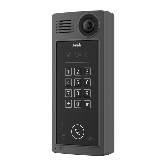
Axis A8207-VE Electrical Wiring Drawings
Network video door station
Hide thumbs
Also See for A8207-VE:
- User manual (88 pages) ,
- Installation manual (11 pages) ,
- Tech note (15 pages)
Summary of Contents for Axis A8207-VE
- Page 1 AXIS A8207-VE Network Video Door Station AXIS A8207-VE MkII Network Video Door Station Electrical Wiring Drawings November 2019 © Axis Communications AB, 2019...
- Page 2 Relay powered by PoE (12V) Configure relay state in the product's webpage PoE+ Switch 1. To check relay state, go to: Hardware > I/O ports > Relays 2. Click Edit. 3. Depending on your lock type, set Normal state to: Open circuit for a fail-secure lock Closed circuit for a fail-safe lock 4.
- Page 3 Two lock relays powered by PoE (12V) Configure relay state in the product's webpage PoE+ Switch 1. To check relay state, go to: Hardware > I/O ports > Relays 2. Click Edit. 3. Depending on your lock type, set Normal state to: Open circuit for a fail-secure lock Closed circuit for a fail-safe lock 4.
- Page 4 One relay powered by PoE (12V), one relay powered by external power supply Configure relay state in the product's webpage PoE+ Switch 1. To check relay state, go to: Hardware > I/O ports > Relays 2. Click Edit. 3. Depending on your lock type, set Normal state to: Open circuit for a fail-secure lock Closed circuit for a fail-safe lock...
- Page 5 Relay powered by PoE (12V), one relay potential-free contact (door chimes etc.) Configure relay state in the product's webpage PoE+ Switch 1. To check relay state, go to: Hardware > I/O ports > Relays 2. Click Edit. 3. Depending on your lock type, set Normal state to: Open circuit for a fail-secure lock Closed circuit for a fail-safe lock...
- Page 6 Power 12V fail-secure lock by PoE+ from door station Configure relay state in the product's webpage PoE+ Switch 1. To check relay state, go to: Hardware > I/O ports > Relays 2. Click Edit. 3. Depending on your lock type, set Normal state to: Open circuit for a fail-secure lock Closed circuit for a fail-safe lock...
- Page 7 Power fail-secure lock by external power supply Configure relay state in the product's webpage PoE+ Switch 1. To check relay state, go to: Hardware > I/O ports > Relays 2. Click Edit. 3. Depending on your lock type, set Normal state to: Open circuit for a fail-secure lock Closed circuit for a fail-safe lock 4.
- Page 8 Relay powered by PoE (24V), one relay potential-free contact (door chimes etc.) Configure relay state in the product's webpage PoE+ Switch 1. To check relay state, go to: Hardware > I/O ports > Relays 2. Click Edit. 3. Depending on your lock type, set Normal state to: Open circuit for a fail-secure lock Closed circuit for a fail-safe lock...
- Page 9 Wire reader to door controller using OSDP Configuration in the product's webpage PoE+ Switch Reader Reader protocol Card types Protocol AUDIO READER I/O 1 READER I/O 2 +MIC- +SPK- - 12 - 12 OSDP - 3V READER DATA 2 READER DATA 1 A- B+ A- B+ D0 D1 A- B+ A- B+ D0 D1 DC IN...
- Page 10 Wire reader to door controller using Wiegand Configuration in the product's webpage PoE+ Switch Reader protocol Card types Protocol Wiegand Beeper AUDIO READER I/O 1 READER I/O 2 +MIC- +SPK- - 12 - 12 - 3V Activate beeper READER DATA 2 READER DATA 1 A- B+ A- B+ D0 D1 A- B+ A- B+ D0 D1...
- Page 11 Wire reader to Axis door controller using VAPIX reader Configuration in the product's webpage PoE+ Switch Reader protocol Card types Protocol VAPIX reader Connect to Axis door controller AUDIO READER I/O 1 READER I/O 2 +MIC- +SPK- - 12 - 12...


Need help?
Do you have a question about the A8207-VE and is the answer not in the manual?
Questions and answers