Axis A8207-VE User Manual
Mk ii network video door station
Hide thumbs
Also See for A8207-VE:
- User manual (88 pages) ,
- Electrical wiring drawings (11 pages) ,
- Installation manual (11 pages)
Table of Contents
Advertisement
Advertisement
Table of Contents

Related Manuals for Axis A8207-VE


Summary of Contents for Axis A8207-VE
- Page 1 AXIS A8207-VE Mk II Network Video Door Station User Manual...
-
Page 2: Table Of Contents
AXIS A8207-VE Mk II Network Video Door Station Table of Contents Solution overview ......... . . -
Page 3: Solution Overview
AXIS A8207-VE Mk II Network Video Door Station Solution overview Solution overview Door station Door station combined with AXIS A9801 Door station combined with AXIS A9161 Door station combined with an access control system, for example AXIS A1001 or AXIS A1601... -
Page 4: Product Overview
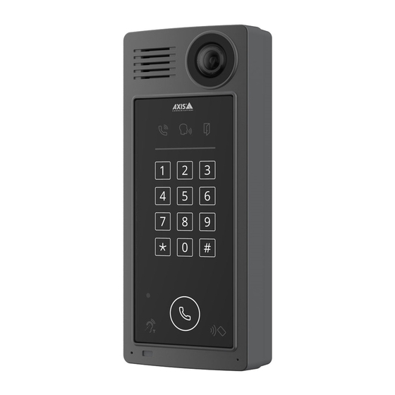
AXIS A8207-VE Mk II Network Video Door Station Product overview Product overview Speaker Camera Call indicator icons on page 22 Card reader indicator stripe on page 22 Keypad Call button on page 22 Card reader icon Microphone PIR-sensor 10 T-coil icon... - Page 5 AXIS A8207-VE Mk II Network Video Door Station Product overview HDMI connector on page 23 (microHDMI) Power connector on page 25 Network connector on page 23 (PoE+) Relay connector on page 23 Relay connector on page 23 I/O connector on page 24...
-
Page 6: Installation
AXIS A8207-VE Mk II Network Video Door Station Installation Installation To watch this video, go to the web version of this document. www.axis.com/products/online-manual/62351#t10170588 Installation video for A8207-VE reader. To watch this video, go to the web version of this document. -
Page 7: Get Started
Get started Find the device on the network To find Axis devices on the network and assign them IP addresses in Windows®, use AXIS IP Utility or AXIS Device Manager. Both applications are free and can be downloaded from axis.com/support. -
Page 8: Verify That No One Has Tampered With The Firmware
Verify that no one has tampered with the firmware To make sure that the device has its original Axis firmware, or to take full control of the device after a security attack: 1. Reset to factory default settings. See Reset to factory default settings on page 19. -
Page 9: Additional Settings
AXIS A8207-VE Mk II Network Video Door Station Additional settings Additional settings This section will cover all the important configurations that an installer needs to do to get the product up and running after the hardware installation has been completed. -
Page 10: Set Up Sip Through A Server (Pbx)
AXIS A8207-VE Mk II Network Video Door Station Additional settings Note Use NAT traversal when the device is connected to the network from behind a NAT router or a firewall. For more information see . 10. Click Save. Set up SIP through a server (PBX) VoIP (Voice over IP) is a group of technologies that enables voice and multimedia communication over IP networks. -
Page 11: Configure The Call Button
Important The network connection only works with Axis door controllers. To connect to a non-Axis door controller, you need to physically connect the devices with wires. See Set up as card reader - wired connection on page 12. -
Page 12: Set Up As Card Reader - Wired Connection
AXIS A8207-VE Mk II Network Video Door Station Additional settings 4. Enter the IP address for the door controller. 5. Enter the credentials for the door controller. 6. Click Connect. 7. Select the entrance reader for the appropriate door. 8. Click Save. -
Page 13: Use Dtmf To Unlock The Door For A Visitor
AXIS A8207-VE Mk II Network Video Door Station Additional settings 2. Under Data sets for active chip types, select the chip type you want to edit and click Add data set. 3. Enter information about the card data. What information to enter depends on the card type and how the cards were enrolled. -
Page 14: Transmit Live Video To A Monitor
AXIS A8207-VE Mk II Network Video Door Station Additional settings 7. Change Duration to 00:00:07, which means that the door is open for 7 seconds. 8. Click Save. Transmit live video to a monitor Your device can transmit a live video stream to an HDMI monitor without a network connection. Use the monitor to see who is at the door. -
Page 15: Learn More
In the Axis product, VoIP is enabled through the Session Initiation Protocol (SIP) and Dual-Tone Multi-Frequency (DTMF) signaling. Example When you press the call button on an Axis door station, a call is initiated to one or more predefined recipients. When a recipient replies, a call is established. The voice and video is transferred through VoIP technologies. - Page 16 Example sip:mydoor@company.com sip:myspeaker@company.com PBX sip.company.com sip:office@company.com When you press the call button on an Axis door station, the call is forwarded through one or more PBXs to a SIP address either on the local IP network or over the internet.
-
Page 17: Set Up Rules For Events
To learn more, check out our guide Get started with rules for events. Applications AXIS Camera Application Platform (ACAP) is an open platform that enables third parties to develop analytics and other applications for Axis products. To find out more about available applications, downloads, trials and licenses, go to axis.com/applications. -
Page 18: Daily Use
AXIS A8207-VE Mk II Network Video Door Station Daily use Daily use Use the keypad I want to... Action Call someone who can let me into the building. Press Call a person in the building. Enter the person’s speed dial number and press Open the door with my card and PIN. -
Page 19: Troubleshooting
5. Use the installation and management software tools to assign an IP address, set the password, and access the device. The installation and management software tools are available from the support pages on axis.com/support. You can also reset parameters to factory default through the device’s webpage. Go to Maintenance > Factory default and click Default. -
Page 20: Technical Issues, Clues And Solutions
Axis device. Check all cabling and reinstall the device. Possible IP address conflict The static IP address in the Axis device is used before the DHCP server sets a dynamic address. with another device on the... - Page 21 Heavy network utilization due to poor infrastructure affects the bandwidth. • Viewing on poorly performing client computers lowers perceived performance and affects frame rate. • Running multiple AXIS Camera Application Platform (ACAP) applications simultaneously may affect the frame rate and the general performance.
-
Page 22: Specifications
AXIS A8207-VE Mk II Network Video Door Station Specifications Specifications Front panel indicators and controls When you connect the product to power, the indicator icons and the indicator strip light up for a few seconds. Call indicator icons Icon Indication Steady blue when outgoing call initiated. -
Page 23: Buttons
AXIS A8207-VE Mk II Network Video Door Station Specifications Buttons Control button The control button is used for: • Resetting the product to factory default settings. See Reset to factory default settings on page 19. Connectors HDMI connector Use the microHDMI connector to connect a display or public view monitor. - Page 24 AXIS A8207-VE Mk II Network Video Door Station Specifications Common 24 V DC For powering auxiliary equipment. Output voltage 24 V DC Note: This pin can only be used as power out. Max current 50 mA Max current 350 mA...
- Page 25 AXIS A8207-VE Mk II Network Video Door Station Specifications DC output Can be used to power auxiliary equipment. 12 V DC Note: This pin can only be used as power out. Max load = 50 mA 3–6 Configurable Digital input – Connect to pin 1 to activate, or leave floating...
-
Page 26: Safety Information
AXIS A8207-VE Mk II Network Video Door Station Safety information Safety information Hazard levels DANGER Indicates a hazardous situation which, if not avoided, will result in death or serious injury. WARNING Indicates a hazardous situation which, if not avoided, could result in death or serious injury. - Page 27 User Manual Ver. M2.5 AXIS A8207-VE Mk II Network Video Door Station Date: May 2022 © Axis Communications AB, 2021 - 2022 Part No. T10176599...
Need help?
Do you have a question about the A8207-VE and is the answer not in the manual?
Questions and answers