Omron J1000 User Manual
J1000 series compact general purpose inverter
Hide thumbs
Also See for J1000:
- System configuration manual (13 pages) ,
- Quick start manual (28 pages)
Table of Contents
Troubleshooting

Related Manuals for Omron J1000


Summary of Contents for Omron J1000
- Page 1 Manual No. SIEP-C71060633-01-OY J1000 Compact General Purpose Inverter Model: JZA 200 V Class Three-Phase Input 0.1 to 0.4 kW 200 V Class Single-Phase Input 0.1 to 1.5 kW 400 V Class Three-Phase Input 0.2 to 4.0 kW USER’S MANUAL...
- Page 3 Compact V/f Control Drive User Manual Type: Model: 200 V Class, Single-Phase Input: 0.1 to 1.5 kW 200 V Class, Three-Phase Input: 0.1 to 4.0 kW 400 V Class, Three-Phase Input: 0.2 to 4.0 kW To properly use the product, read this manual thoroughly and retain for easy reference, inspection, and maintenance.
- Page 4 Copyright © 2008 OMRON YASKAWA MOTION CONTROL, B.V. All rights reserved. All rights reserved. No part of this publication may be reproduced, stored in a retrieval system, or transmitted, in any form or by any means, mechanical, electronic, photocopying, recording, or otherwise, without the prior written permission of OYMC.
-
Page 5: Table Of Contents
3.2 Standard Connection Diagram................32 3.3 Main Circuit Connection Diagram............... 34 Single-Phase 200 V Class (JZAB0P1 ~ B1P5) ..............34 Three-Phase 200 V Class (JZA20P1 ~ 24P0); Three-Phase 400 V Class (JZA40P2 ~ 44P0) ..........................34 3.4 Terminal Block Configuration ................35 3.5 Protective Covers .................... - Page 6 5. PARAMETER DETAILS ..................69 5.1 A: Initialization ....................... 70 A1: Initialization ..........................70 5.2 b: Application......................... 72 b1: Mode of Operation........................72 b2: DC Injection Braking....................... 76 5.3 C: Tuning........................77 SIEP C710606 33A OYMC AC Drive – J1000 User Manual...
- Page 7 Alarm and Error Displays ......................121 6.4 Fault Detection ......................123 Fault Displays, Causes and Possible Solutions ................. 123 6.5 Alarm Detection ......................129 Alarm Codes, Causes, and Possible Solutions ................129 SIEP C710606 33A OYMC AC Drive – J1000 User Manual...
- Page 8 Fault Reset Methods ........................133 6.8 Troubleshooting without Fault Display ..............134 Cannot Change Parameter Settings ..................134 Motor Does Not Rotate Properly after Pressing RUN Button or after Entering External Run Command ..........................134 7. PERIODIC INSPECTION & MAINTENANCE ..........139 7.1 Section Safety......................
- Page 9 L: Protection Function ........................ 177 n: Advanced Performance Set-Up....................180 o: Operator Related Parameters ....................180 U: Monitors ..........................181 B.3 Defaults by Drive Capacity (o2-04) and ND/HD (C6-01) ........... 183 C. MEMOBUS/MODBUS COMMUNICATIONS............185 C.1 Section Safety......................186 C.2 MEMOBUS/Modbus Configuration ................187 C.3 Communication Specifications ..................
- Page 10 CE Low Voltage Directive Compliance..................212 EMC Guidelines Compliance ..................... 212 D.3 UL Standards ....................... 218 UL Standards Compliance ......................218 Drive Motor Overload Protection ....................219 D.4 User Setting Table ....................... 221 INDEX .......................223 SIEP C710606 33A OYMC AC Drive – J1000 User Manual...
-
Page 11: Preface & General Safety
Preface & General Safety This section provides safety messages pertinent to this product, that, if not heeded, may result in fatality, personal injury, or equipment damage. OYMC is not responsible for the consequences of ignoring these instructions. PREFACE......................10 GENERAL SAFETY..................11... -
Page 12: Preface
OYMC must be supplied to the end user with appropriate warnings and instructions as to the safe use and operation of that part. Any warnings provided by OYMC must be promptly provided to the end user. -
Page 13: General Safety
• When ordering a new copy of the manual due to damage or loss, contact your OYMC representative or the nearest OYMC sales office and provide the manual number shown on the front cover. - Page 14 The charge indicator LED will extinguish when the DC bus voltage is below 50 Vdc. To prevent electric shock, wait at least one minute after all indicators are OFF and measure the DC bus voltage level to confirm safe level.
-
Page 15: Drive Label Warnings
Figure i.2 Warning Information Position Warranty Information Restrictions The J1000 was not designed or manufactured for use in devices or systems that may directly affect or threaten human lives or health. SIEP C710606 33A OYMC AC Drive – J1000 User Manual... -
Page 16: Quick Reference
This product has been manufactured under strict quality-control guidelines. However, if this product is to be installed in any location where failure of this product could involve or result in a life-and-death situation or loss of human life or in a facility where failure may cause a serious accident or physical injury, safety devices must be installed to minimize the likelihood of any accident. -
Page 17: Receiving
Receiving This chapter describes the proper inspections to perform after receiving the drive and illustrates the different enclosure types and components. SECTION SAFETY....................16 MODEL NUMBER AND NAMEPLATE CHECK..........17 COMPONENT NAMES..................19 SIEP C710606 33A OYMC AC Drive – J1000 User Manual... -
Page 18: Section Safety
Observe proper electrostatic discharge procedures (ESD) when handling the drive and circuit boards. Failure to comply may result in ESD damage to the drive circuitry. A motor connected to a PWM drive may operate at a higher temperature than a utility-fed motor and the operating speed range may reduce motor cooling capacity. -
Page 19: Model Number And Nameplate Check
If the drive appears damaged upon receipt, contact the shipper immediately. • Verify receipt of the correct model by checking the information on the nameplate. • If you have received the wrong model or the drive does not function properly, contact your supplier. Nameplate... - Page 20 40P4 40P4 0.75 40P7 0.75 40P7 41P5 41P5 42P2 42P2 43P0 43P0 44P0 44P0 11.1 <1> Drives with these specifications do not guarantee complete protection for the specified environmental condition. SIEP C710606 33A OYMC AC Drive – J1000 User Manual...
-
Page 21: Component Names
Figure 1.2 Exploded View of IP20/Open-Chassis Type Components Three-Phase AC200 V JZA20P7B <1> The drives JZAB0P1B ~ JZAB0P4B and JZA20P1B ~ JZA20P4B do not have a cooling fan or a cooling fan cover. SIEP C710606 33A OYMC AC Drive – J1000 User Manual... - Page 22 Figure 1.3 Exploded view of IP20/Open-Chassis Type Components Three-Phase AC200 V JZA22P2B <1> The drives JZAB0P7B and 40P2B ~ 40P7B do not have a cooling fan or a cooling fan cover. SIEP C710606 33A OYMC AC Drive – J1000 User Manual...
-
Page 23: Front Views
C – Control circuit terminal Refer to Control Circuit Wiring on page 40 D – Main circuit terminal Refer to Wiring the Main Circuit Terminal on page 39 Figure 1.4 Front Views of Drives SIEP C710606 33A OYMC AC Drive – J1000 User Manual... - Page 24 1.3 Component Names This Page Intentionally Blank SIEP C710606 33A OYMC AC Drive – J1000 User Manual...
-
Page 25: Mechanical Installation
Mechanical Installation This chapter explains how to properly mount and install the drive. SECTION SAFETY....................24 MECHANICAL INSTALLATION...............26 SIEP C710606 33A OYMC AC Drive – J1000 User Manual... -
Page 26: Section Safety
Observe proper electrostatic discharge (ESD) procedures when handling the drive. Failure to comply could result in ESD damage to the drive circuitry. It may be difficult to perform maintenance on the cooling fans of drives installed in a vertical row inside an enclosure. - Page 27 2.1 Section Safety NOTICE When the input voltage is 440 V or higher or the wiring distance is greater than 100 meters, pay special attention to the motor insulation voltage or use a drive-rated motor. Failure to comply could lead to motor winding failure.
-
Page 28: Mechanical Installation
NOTICE: Prevent foreign matter such as metal shavings or wire clippings from falling into the drive during installation and project construction. Failure to comply could result in damage to the drive. Place a temporary cover over the top of the drive during installation. -
Page 29: Installation Orientation And Spacing
Figure 2.3 Space Between Drives (Side-by-Side Mounting) Note: When installing drives of different heights in the same enclosure panel, the tops of the drives should line up. Leave space between the top and bottom of stacked drives for cooling fan replacement if required. Using this method, it is possible to replace the cooling fans later. - Page 30 B1P5B 145.5 21P5B 120.5 Three-Phase 22P2B 137.5 200 V Class 24P0B 134.5 40P2B 72.5 40P4B 90.5 40P7B 137.5 Three-Phase 41P5B 145.5 400 V Class 42P2B 145.5 43P0B 145.5 44P0B 134.5 SIEP C710606 33A OYMC AC Drive – J1000 User Manual...
-
Page 31: Electrical Installation
Electrical Installation This chapter explains proper procedures for wiring the control circuit terminals, motor and power supply. SECTION SAFETY....................30 STANDARD CONNECTION DIAGRAM............32 MAIN CIRCUIT CONNECTION DIAGRAM............34 TERMINAL BLOCK CONFIGURATION............35 PROTECTIVE COVERS..................36 MAIN CIRCUIT WIRING..................37 CONTROL CIRCUIT WIRING................40 I/O CONNECTIONS...................44 MAIN FREQUENCY REFERENCE..............46 3.10 BRAKING RESISTOR..................47... -
Page 32: Section Safety
The charge indicator LED will extinguish when the DC bus voltage is below 50 Vdc. To prevent electric shock, wait at least one minute after all indicators are off and measure the DC bus voltage level to confirm safe level. - Page 33 Failure to comply could result in damage to the drive and will void warranty. OYMC is not responsible for any modification of the product made by the user. This product must not be modified. SIEP C710606 33A OYMC AC Drive – J1000 User Manual...
-
Page 34: Standard Connection Diagram
240 Vac maximum (200 V Class) and 480 Vac maximum (400 V Class). NOTICE: When the input voltage is 440 V or higher or the wiring distance is greater than 100 meters, pay special attention to the motor insulation voltage or use a drive duty motor. Failure to comply could lead to motor insulation breakdown. - Page 35 WARNING! When 3-Wire sequence is used, set the drive to 3-Wire sequence before wiring the control terminals and ensure parameter b1-17 is set to 0 (drive does not accept a run command at power up (default). If the drive is wired for 3-Wire sequence but set up for 2- Wire sequence (default) and if parameter b1-17 is set to 1 (drive accepts a Run command at power up), the motor will rotate in reverse direction at power up of the drive and may cause injury.
-
Page 36: Main Circuit Connection Diagram
The main circuit DC power supply powers the control circuit. NOTICE: Do not use the negative DC bus terminal “-” as a ground terminal. This terminal is at high voltage DC potential. Improper wiring connections could result in damage to the drive. -
Page 37: Terminal Block Configuration
3.4 Terminal Block Configuration Terminal Block Configuration The figures in this section provide illustrations of the main circuit terminal block configurations of the different drive sizes. Models: Models: JZAB0P7, B1P5 JZAB0P1, B0P2, B0P4 JZA21P5, 22P2, 24P0 JZA20P1, 20P2, 20P4, 20P7... -
Page 38: Protective Covers
Figure 3.6 Remove the Front Cover on an IP20/Open-Chassis Drive Apply pressure to the tabs on each side of the terminal cover. Pull the terminal cover away from the drive while pushing in on the tabs to pull the cover free. -
Page 39: Main Circuit Wiring
30 °C and wiring distance less than 100 m. 2. Terminals +1, +2, –, B1 and B2 are for connecting optional devices such as a DC reactor or braking resistor. Do not connect other non-specified devices to these terminals. -
Page 40: Main Circuit Terminal Power Supply And Motor Wiring
NOTICE: Do not connect the AC power line to the output motor terminals of the drive. Failure to comply could result in death or serious injury by fire as a result of drive damage from line voltage application to output terminals. - Page 41 WARNING! Electrical Shock Hazard. Shut off the power supply to the drive before wiring the main circuit terminals. Failure to comply may result in death or serious injury. Note: A cover placed over the DC Bus and braking circuit terminals prior to shipment helps prevent miswiring. Cut away covers as needed for terminals with a needle-nose pliers.
-
Page 42: Control Circuit Wiring
WARNING! Sudden Movement Hazard. Always check the operation and wiring of control circuits after being wired. Operating a drive with untested control circuits could result in death or serious injury. WARNING! Confirm the drive I/O signals and external sequence before starting test run. Failure to comply may result in death or serious injury. -
Page 43: Terminal Configuration
Single: 0.25 to 1.5 (24 to 16) Ferrule-Type Wire Terminations Crimp a ferrule to signal wiring to improve wiring simplicity and reliability. Use CRIMPFOX ZA-3, a crimping tool manufactured by PHOENIX CONTACT. SIEP C710606 33A OYMC AC Drive – J1000 User Manual... -
Page 44: Wiring Procedure
This section describes the proper procedures and preparations for wiring the control terminals. WARNING! Electrical Shock Hazard. Do not remove covers or touch the circuit boards while the power is on. Failure to comply could result in death or serious injury. - Page 45 NOTICE: The analog signal lines between the drive and the operator station or peripheral equipment should not exceed 50 meters when using an analog signal from a remote source to supply the frequency reference. Failure to comply could result in poor system performance.
-
Page 46: I/O Connections
I/O Connections Sinking/Sourcing Mode Switch Set the DIP switch S3 on the front of the drive to switch the digital input terminal logic between sinking mode and sourcing mode; the drive is preset to sinking mode. Table 3.10 Sinking/Sourcing Mode Setting... - Page 47 REV Run/Stop SOURCE SINK External Fault N.O. Fault reset External power supply Multi-step speed 1 +24V SINK +24V SOURCE Figure 3.18 Source Mode: Sequence from PNP Transistor (+24 V Common) SIEP C710606 33A OYMC AC Drive – J1000 User Manual...
-
Page 48: Main Frequency Reference
H3-01 to “0” (0 to +10 Vdc with lower limit) or “1” (0 to +10 Vdc without lower limit). To use current input at terminal A1, set the DIP switch S1 to "I" and set parameter H3-01 = “2” or “3” (4-20 mA or 0-20 mA). -
Page 49: Braking Resistor
Carefully review the braking resistor instruction manual when connecting a braking option to the drive. Note: The braking circuit must be sized properly in order to dissipate the power required to decelerate the load in the desired time. Ensure that the braking circuit can dissipate the energy for the set deceleration time prior to running the drive. -
Page 50: Interlocking With Connected Machinery
Drive Ready Signal The "Drive ready" signal is output to one of the multi-function terminals after the drive has booted up and there is no fault present. It indicates that the drive is ready for operation. -
Page 51: Wiring Checklist
Properly wire the drive and motor together. The motor lines and drive output terminals R/T1, V/T2 and W/T3 should match in order to produce the desired phase order. If the phase order is incorrect, the drive will rotate in the opposite direction. - Page 52 3.12 Wiring Checklist This Page Intentionally Blank SIEP C710606 33A OYMC AC Drive – J1000 User Manual...
-
Page 53: Start-Up Programming & Operation
Start-Up Programming & Operation This chapter explains the functions of the LED operator and how to program the drive for initial operation. SECTION SAFETY....................52 USING THE DIGITAL LED OPERATOR............54 THE DRIVE AND PROGRAMMING MODES............57 START-UP FLOWCHART.................62 POWERING UP THE DRIVE................63 NO-LOAD OPERATION TEST RUN..............64... -
Page 54: Section Safety
The charge indicator LED will extinguish when the DC bus voltage is below 50 Vdc. To prevent electric shock, wait at least one minute after all indicators are off and measure the DC bus voltage level to confirm safe level. - Page 55 Failure to comply could result in damage to the drive and will void warranty. OYMC is not responsible for any modification of the product made by the user. This product must not be modified. Check all the wiring to ensure that all connections are correct after installing the drive and connecting any other devices.
-
Page 56: Using The Digital Led Operator
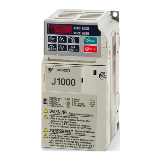
4.2 Using the Digital LED Operator Using the Digital LED Operator Use the LED operator to enter run and stop commands, display data, edit parameters, as well as display fault and alarm information. Keys, Displays, and LEDs STOP STOP J1000 WARNING Risk of electric shock. -
Page 57: Digital Text Display
Refer to LED Screen Displays on page DRV LED Light FOUT LED Light Digital Text Display Text appears on the LED Operator as shown below. This section explains the meaning of text as it appears on the display screen. Flashing Table 4.2 Digital Text Display... -
Page 58: Menu Structure For Digital Led Operator
The drive will display the actual setting values. Output Voltage Monitor Display Verify Menu Set Up Mode Parameter Setting Mode Figure 4.3 Digital LED Operator Screen Structure <1> Reverse can only be selected when LOCAL is set. SIEP C710606 33A OYMC AC Drive – J1000 User Manual... -
Page 59: The Drive And Programming Modes
“Up arrow” is scrolled immediately after powering up the drive. Note: When b1-08 (Run Command Selection while in Programming Mode) is set to 1 (enabled), the drive can run even if the mode is switched to the programming mode. - Page 60 • View information on an alarm. Note: Select "Drive Mode" when running. The mode can be switched to any mode (program mode, etc.) other than drive mode while the drive is stopped. However, the drive cannot be operated in other modes. Return the mode to "Drive Mode" after completing periodic inspection.
-
Page 61: Changing Parameter Settings Or Values
. The Verify menu also allows users to access and re-edit edited parameters. Note: The Verify Menu will not display parameters from the A1 group even if those parameters have been changed from default settings. SIEP C710606 33A OYMC AC Drive – J1000 User Manual... -
Page 62: Switching Between Local And Remote
WARNING! Sudden Movement Hazard. The drive may start unexpectedly if the Run command is already applied when switching from LOCAL mode to REMOTE mode when b1-07 = 1, resulting in death or serious injury. Be sure all personnel are clear of rotating machinery and electrical connections prior to switching between LOCAL mode and REMOTE mode. - Page 63 E1-01 Input Voltage Reference H4-02 Terminal AM Gain Setting E1-04 Maximum Output Frequency L1-01 Motor Protection Function Selection E1-05 Maximum Voltage L3-04 Stall Prevention Selection during Deceleration E1-06 Base Frequency SIEP C710606 33A OYMC AC Drive – J1000 User Manual...
-
Page 64: Start-Up Flowchart
4.4 Start-up Flowchart Start-up Flowchart This section summarizes the basic steps required to start the drive. The flowchart is intended as a quick reference to help familiarize the user with start-up procedures. Flowchart: Basic Start-up Figure 4.6 describes basic start-up sequence for the drive and motor system. This sequence varies slightly depending on application. -
Page 65: Powering Up The Drive
Notes when Setting the V/f Pattern Set the maximum output frequency to match the motor characteristics. If the V/f pattern voltage is increased motor torque may also increase. However, if the V/f voltage is set too high these problems may occur: •... -
Page 66: No-Load Operation Test Run
4.6 No-Load Operation Test Run No-Load Operation Test Run No-Load Operation Test Run This section explains how to operate the drive with the motor uncoupled from the load during a test run. Before Starting the Motor Check the following items before operation: •... -
Page 67: Test Run With Load Connected
Test run the application similarly to the no-load test procedure when connecting the machinery to the motor. • Check monitor parameter U1-03 to ensure there is no overcurrent. • If the application permits running the load in the reverse direction, try changing motor direction and the frequency reference while watching for abnormal motor oscillation or vibration. -
Page 68: Verifying And Backing Up Parameter Settings
Parameter settings can be copied to another drive to simplify parameter restoration or multiple drive setup. The drive supports the following options: USB/Copy Unit The copy unit is an external option connected to the drive to copy parameter settings to another drive. It includes a USB adapter to connect the drive to a PC. CX-Drive CX-Drive is a PC software tool for parameter management, monitoring, and diagnosis. -
Page 69: Test Run Checklist
Check the items that correspond to the control mode being used. WARNING! Ensure start/stop and safety circuits are wired properly and in the correct state before energizing the drive. Failure to comply could result in death or serious injury from moving equipment. When programmed for 3-Wire control, a momentary closure on terminal S1 may cause the drive to start. - Page 70 4.9 Test Run Checklist This Page Intentionally Blank SIEP C710606 33A OYMC AC Drive – J1000 User Manual...
-
Page 71: Parameter Details
Parameter Details A: INITIALIZATION...................70 B: APPLICATION....................72 C: TUNING......................77 D: REFERENCE SETTINGS................82 E: MOTOR PARAMETERS................86 H: TERMINAL FUNCTIONS................90 L: PROTECTION FUNCTIONS...............102 N: SPECIAL ADJUSTMENTS.................111 O: OPERATOR RELATED SETTINGS............112 5.10 U: MONITOR PARAMETERS.................116 SIEP C710606 33A OYMC AC Drive – J1000 User Manual... -
Page 72: A: Initialization
How to use the Password The user can set a password for the drive to restrict access. The password is set to A1-05 and must be entered to A1-04 to unlock parameter access. Until the correct password is entered, the following parameters cannot be viewed or edited: A1-01 and A1-03. - Page 73 11. The display automatically returns to the parameter display. Note: Parameter settings can be edited after entering the correct password. Performing a 2-Wire or 3-Wire initialization resets the password to “0000”. Reenter the password to parameter A1-05 after drive initialization.
-
Page 74: B: Application
Use parameter b1-01 to select the frequency reference source for the REMOTE mode. Note: 1. If a Run command is input to the drive but the frequency reference entered is 0 or below the minimum frequency, the RUN indicator LED on the digital operator will light and the STOP indicator will flash. - Page 75 Note: If the frequency reference source is set for the potentiometer option (b1-01 = 3) but an option board is not installed, an oPE05 Programming Error will be displayed on the digital operator and the RUN command will not be accepted.
- Page 76 Figure 5.4 Coast to Stop Note: After a stop is initiated, any subsequent Run command that is entered will be ignored for a certain time. Do not attempt to start the motor again until it has come to a complete stop. To start the motor before it has stopped completely, use DC Injection at start...
- Page 77 If the Run command is issued differently in the old and new control source (e.g. old - terminals, new - serial communications) and it is active at the new source when switching takes place, the drive will either not start or it will stop if it was running before.
-
Page 78: B2: Dc Injection Braking
The Run command has to be cycled to start the drive. Note: For safety reasons, the drive is initially set up not to accept a Run command at power up (b1-17 = "0"). If a Run command is issued at power up, the RUN indicator LED will flash quickly. -
Page 79: C: Tuning
C1-04 Deceleration Time 2 Switching Acceleration Times by Digital Input Accel/decel times 1 are active by default if no input is set. The accel/decel time 2 can be activated by a digital input (H1- = 7) as explained in Table 5.5. -
Page 80: C3: Slip Compensation
C3: Slip Compensation The Slip Compensation function prevents motor speed loss due to an increase in load. Note: Before making changes to the Slip Compensation parameters, make sure the motor parameters and V/f pattern are set properly. C3-01: Slip Compensation Gain This parameter sets the gain for the motor slip compensation function. -
Page 81: C6: Carrier Frequency
10.0 kHz User defined (C6-03 to C6-05) Note: Swing PWM uses 2.0 kHz carrier frequency as a base but by applying special PWM patterns the audible noise of the motor is kept low. Guidelines for Carrier Frequency Parameter Setup SIEP C710606 33A OYMC AC Drive – J1000 User Manual... - Page 82 <1> The carrier frequency may need to be lowered if the motor cable is too long. Refer to the table below. <2> In Normal Duty default setting is 7 (Swing PWM), equivalent to setting 2 kHz. Increasing the carrier frequency is fine when using the drive is set for Normal Duty, but remember that the drive rated current falls when the carrier frequency is increased.
- Page 83 2 kHz 10 kHz 15 kHz B0P7 20P7 Table 5.8 Drives with Heavy Duty Default Carrier Frequency of 8 kHz 200 V Single Phase Units 200 V Three Phase Units 400 V Three Phase Units Rated Current [A] Rated Current [A]...
-
Page 84: D: Reference Settings
Depending on how many speeds are used, some digital inputs have to be programmed for Multi-Step Speed Selection 1, 2, 3 and 4 (H1- = 3, 4, 5). For the Jog reference a digital input must be set to H1- = 6. -
Page 85: D2: Frequency Upper/Lower Limits
Sets the minimum frequency reference as a percentage of the maximum output frequency. This limit applies to all frequency references. If a lower reference than this value is input, the drive will run at the d2-02 level. If the drive is started with a lower reference than d2-02, it will accelerate up to d2-02. -
Page 86: D3: Jump Frequency
Figure 5.11 Jump Frequency Operation Note: 1. The drive will use the active accel/decel time to pass through the specified dead band range but will not allow continuous operation in that range. 2. When using more than one Jump frequency, make sure that d3-01 ≥ d3-02. - Page 87 • Acceleration Hold The last hold value will be saved when the Run command or the drive power is switched off. The drive will use the value that was saved as the frequency reference when it restarts. The accel/decel hold input must be enabled the entire time or else the hold value will be cleared.
-
Page 88: E: Motor Parameters
(overvoltage, Stall Prevention, etc.). NOTICE: Set parameter E1-01 to match the input voltage of the drive. Drive input voltage (not motor voltage) must be set in E1-01 for the protective features of the drive to function properly. Failure to comply could result in improper drive operation. - Page 89 Table 5.14 Rated Output Operation, Examples 12 to 14 Example 12 90 Hz Example 13 120 Hz Example 14 180 Hz 1.5 3 1.5 3 1.5 3 Frequency (Hz) Frequency (Hz) Frequency (Hz) SIEP C710606 33A OYMC AC Drive – J1000 User Manual...
-
Page 90: E2: Motor 1 Parameters
2. To make the V/f pattern a straight line set E1-09 = E1-07. In this case the E1-08 setting is disregarded. 3. E1-03 is unaffected when the drive is initialized using parameter A1-03, but the settings for E1-04 through E1-10 are returned to their default values. - Page 91 Note: The setting range becomes 0.00 to 130.00 when using JZAB0P2, JZA20P2, JZA40P2 and smaller. Contact the motor manufacturer to find out the line-to-line resistance or measure it manually. When using the manufacturer Motor Test Report, calculate E2-05 by the formulas below.
-
Page 92: H: Terminal Functions
S1 becomes the Run command input, and S2 becomes the Stop command input. The drive will start the motor when the Run input S1 is closed for longer than 50 ms. The drive will stop the operation when the Stop input S2 is released for a brief moment. Whenever the input programmed for 3-Wire sequence is open, the drive will be set for forward direction. - Page 93 Note: 1. The Run and Stop command must be open/closed for a short moment only to start and stop the drive. 2. If the Run command is active at power up and b1-17 = 0 (Run command at power up not accepted), the Run LED will flash to indicate that protective functions are operating.
- Page 94 Setting F: Not Used/Through Mode Any digital input that is not used should be set to F. When set to “F”, an input does not trigger any function in the drive. Setting F, however, still allows the input status to be read out by a PLC via an optional MEMOBUS/Modbus communications interface .
- Page 95 Up or Down command are active. It will not start running if only the Run command is on. • If the lower limit is set by both an analog input and d2-02, and the analog limit is higher than the d2-02 value, the drive will accelerate to the d2-02 value when a Run command is input.
- Page 96 Sets the drive for 2-Wire sequence. When the input set to 40 is closed, the drive operates in the forward direction. When the input set for 41 is closed, the drive will operate in reverse. Closing both inputs at the same time will result in an external fault.
-
Page 97: H2: Multi-Function Output
Terminal MA, MB and MC Function Selection (relay) 0 to 13D E: Fault Note: If not using an input terminal or if using it in the through-mode, be sure to set that terminal to “F”. Table 5.16 Multi-Function Output Terminal Settings Setting... - Page 98 Setting 4: Frequency Detection 1 Output is closed as long as the output frequency is below the detection level set in L4-01 plus 2 Hz. It closes when the output frequency falls below L4-01.
- Page 99 Output closes whenever the DC bus voltage or control circuit power supply drops below the trip level. The undervoltage trip level depends on the setting of parameter E1-01. Refer to E1-01 for details. A fault in the DC bus charge circuit will also cause the DC Bus Undervoltage output to close.
-
Page 100: H3: Analog Input Terminal A1 Settings
Example: Terminal A1 is set to supply the frequency reference, and the bias (H3-04) is set to -100%. The frequency reference can be set from 0 to 100% with an analog input of 5 to 10 V. The frequency reference will be zero when the analog input is between 0 and 5 V. - Page 101 Example: Terminal A1 is set to supply the frequency reference, and the bias (H3-04) is set to -100%. The frequency reference can be set from 0 to 100% with an analog input of 5 to 10 V. With an input of 0 to 5 V, the frequency reference can be set from -100% to 0%.
- Page 102 • Gain H3-03 = 200%, A1 as frequency reference input: An input 10 Vdc will be equivalent to a 200% frequency reference and 5 Vdc will be equivalent to a 100% frequency reference. Since the drive output is limited by the maximum frequency parameter (E1-04), the frequency reference will be equal to E1-04 above 5 Vdc.
-
Page 103: H4: Multi-Function Analog Output Terminal Am
5.6 H: Terminal Functions H3-13: Analog Input Filter Time Constant Parameter H3-13 sets the time constant for a first order filter that will be applied to analog input A1 and also to the reference value from potentiometer option (AI-V3/J). Name... -
Page 104: L: Protection Functions
Setting 2: Drive Dedicated Motor (constant torque, 1:10) Use this setting when operating a drive duty motor with a torque ratio of 1:10. This motor type is allowed to run with 100% load from 10% up to 100% speed. Running slower speeds with full load can trigger an overload fault. -
Page 105: L2: Momentary Power Loss Ride-Thru
Speed (%) L1-02: Motor Overload Protection Time Sets the time it takes the drive to detect motor overheat due to overload. This setting rarely requires adjustment, but should correlate with the motor overload tolerance protection time for performing a hot start. -
Page 106: L3: Stall Prevention
1. A Uv1 fault is not triggered. Note: 1. When L2-01 is set to 1 or 2, and a magnetic contactor between motor and drive is used, be sure that the magnetic contactor is kept close as long as the drive attempts to restart. - Page 107 0 to 150% <1> The upper limit and default value is determined by the duty rating and the carrier frequency derating selection (C6-01 and L8-38 respectively). If stalling occurs with L3-02 set to its default value when using a motor that is relatively small compared to the drive, try lowering L3-02.
-
Page 108: L4: Speed Agree
Note: When output frequency is 6 Hz or less, Stall Prevention During Run is disabled regardless of the setting in L3-05/06. Setting 0: Disabled Drive runs at the set frequency reference. A heavy load may cause the motor to stall and trip the drive with an oC or oL fault. -
Page 109: L5: Fault Restart
• The braking sequence should be designed as follows: • A normally open signal (N.O.) should be used to control the brake so that it is released when terminal MA-MC closes. • An external circuit should be added to ensure the brake is fully applied in case of a fault or emergency condition. -
Page 110: L6: Torque Detection
L6: Torque Detection The drive provides a torque detection function that triggers an alarm or fault signal when the load is too heavy (oL). It is set up using the L6- parameters. To indicate an overload condition to an external device, the digital output should be programmed as shown below. -
Page 111: L8: Hardware Protection
0 or 1 Setting 0: Run with Timer The fan is switched on when a Run command is active. It is switched off 60 s after the Run command has been released. Using this setting extends the fan lifetime. Setting 1: Run always The fan runs whenever power is supplied to the drive. - Page 112 • Above 7 Hz when the current exceeds 112% of the drive rated current. The drive uses the delay time of 0.5 s and a hysteresis of 12% when switching the carrier frequency back to the set value. SIEP C710606 33A OYMC AC Drive – J1000 User Manual...
-
Page 113: N: Special Adjustments
• The drive decelerates at the active deceleration time. Make sure to set this time so that no overvoltage (ov) fault occurs. • When a Run command is entered during overexcitation deceleration, overexcitation operation is cancelled and the drive will reaccelerate to the specified speed. -
Page 114: O: Operator Related Settings
These parameters determine the functions assigned to the operator keys. o2-02: STOP Key Function Selection Selects if the STOP key on the digital operator can be used to stop the operation when the drive is controlled from a remote source (i.e., not from digital operator). -
Page 115: O3: Copy Function
2. Drive performance will suffer if the correct drive capacity is not set to o2-04, and protective functions will fail to operate properly. o2-05: Frequency Reference Setting Method Selection Determines if the ENTER key must be used to input a frequency reference from the digital operator. -
Page 116: O4: Maintenance Monitor Settings
U4-01. Note: The value in o4-01 is set in 10 h units. For example, a setting of 30 will set the cumulative operation time counter to 300 h. 300 h will also be displayed in monitor U4-01. - Page 117 The drive keeps a record of the fault history. Setting 1: Reset Fault Data Resets the data for the U2- monitors. Once o4-11 is set to 1 and the ENTER key is pressed, the fault data are erased and the display returns to 0.
-
Page 118: U: Monitor Parameters
U1- monitors and descriptions. U2: Fault History The fault history monitors can be used to view the current and the last occurred fault. Refer to U2: Fault History on page for a list of U2- monitors and descriptions. -
Page 119: Troubleshooting
Troubleshooting This chapter provides descriptions of the drive faults, alarms, errors, related displays, and possible solutions. This chapter can also serve as a reference guide for tuning the drive during a trial run. SECTION SAFETY..................118 MOTOR PERFORMANCE FINE TUNING............120 DRIVE ALARMS, FAULTS, AND ERRORS...........121 FAULT DETECTION..................123... -
Page 120: Section Safety
Before wiring terminals, disconnect all power to the equipment. The internal capacitor remains charged even after the drive input power is turned off. The charge indicator LED will extinguish when the DC bus voltage is below 50 Vdc. To prevent electric shock, wait at least one minute after all indicators are off and measure the DC bus voltage level to confirm safe level. - Page 121 Failure to comply could result in damage to the drive and will void warranty. OYMC is not responsible for modification of the product made by the user. Check all the wiring after installing the drive and connecting other devices to ensure that all connections are correct.
-
Page 122: Motor Performance Fine Tuning
(C3-01). Note: Use slip compensation to improve speed precision. First make sure that the proper values have been set for the motor rated current to E2-01, motor rated slip (E2-02), and motor no-load current (E2-03). Next, adjust the slip compensation gain set to C3-01 so that it is between 0.5 to 1.5. -
Page 123: Drive Alarms, Faults, And Errors
• The motor does not stop. Alarms • The multi-function contact output closes if set to be tripped by a minor fault (H2-01 = 10), but not by an alarm. • The digital operator displays text indicating a specific alarm and ALM indicator LED flashes. -
Page 124: Operation Errors
Minor Faults and Alarms When a minor fault or alarm occurs, the ALM LED flashes and the text display shows an alarm code. A fault has occurred if the text remains lit and does not flash. Refer to Alarm Detection on page 129. -
Page 125: Fault Detection
• Ensure that other equipment such as switches or relays do not cause noise and use surge suppressors if required. • Separate all wiring for communications devices from drive input power lines. Install a noise filter to the input side of the drive input power. - Page 126 • Check the resistance between the motor cables and the ground terminal . • Replace damaged cables. • Measure the current flowing into the motor. • Replace the drive with a larger capacity unit if the current value exceeds the rated current of the The load is too heavy. drive.
- Page 127 The drive is attempting to operate a • Check the motor capacity. specialized motor or a motor larger than the • Ensure that the rated capacity of the drive is greater than or equal to the capacity rating found on the maximum size allowed. motor nameplate.
- Page 128 External operator is not properly connected to • Replace the cable if damaged the drive. • Turn off the drive input power and disconnect the operator. Next reconnect the operator and turn the drive input power back on. LED Operator Display...
- Page 129 • For 400 V class: approximately 380 V (350 V when E1-01 is less than 400) The fault is output only if L2-01 = 0 or the DC bus voltage is below the Uv detection level for a certain time while L2-01 =...
- Page 130 • Replace the drive if the fault continues to occur. is damaged. • Check monitor U4-06 for the performance life of the inrush prevention circuit. • Replace the drive if U4-06 exceeds 90%. SIEP C710606 33A OYMC AC Drive – J1000 User Manual...
-
Page 131: Alarm Detection
6.5 Alarm Detection Alarm Detection Alarms are drive protection functions that do not operate the fault contact. The drive will return to original status when the cause of the alarm has been removed. During an alarm condition, the Digital Operator display flashes and an alarm output is generated at the multi-function output (H2-01), if programmed. - Page 132 (H1- = 20 to 2F). • Reconnect the signal line. Multi-function contact inputs are set • Check if the unused terminals have been set for H1- = 20 to 2F (External Fault). incorrectly. • Change the terminal settings.
- Page 133 • DC bus voltage dropped below the under voltage detection level. • Contactor to suppress inrush current in the drive was open. • Low voltage in the control drive input power. This alarm outputs only if L2-01 is not 0 and DC bus voltage is below the detection level.
-
Page 134: Operator Programming Errors
An Operator Programming Error (oPE) occurs when an inappropriate parameter is set or an individual parameter setting is inappropriate. The drive will not operate until the parameter is set correctly; however, no alarm or fault outputs will occur. If an oPE occurs, investigate the cause and... -
Page 135: Diagnosing And Resetting Faults
WARNING! Electrical Shock Hazard. Ensure there are no short circuits between the main circuit terminals (R/L1, S/L2, and T/L3) or between the ground and main circuit terminals before restarting the drive. Failure to comply may result in serious injury or death and will cause damage to equipment.
Need help?
Do you have a question about the J1000 and is the answer not in the manual?
Questions and answers