Barco HDX-4K20 FLEX User Manual
Hide thumbs
Also See for HDX-4K20 FLEX:
- User manual (170 pages) ,
- User manual (107 pages) ,
- User manual (222 pages)
Table of Contents
Advertisement
Quick Links
Advertisement
Table of Contents

Related Manuals for Barco HDX-4K20 FLEX


Summary of Contents for Barco HDX-4K20 FLEX
- Page 1 HDX 4K User guide ENABLING BRIGHT OUTCOMES...
- Page 2 Product revision Software Revision: 2.0.x Registered office: Barco NV President Kennedypark 35, 8500 Kortrijk, Belgium www.barco.com/en/support www.barco.com Barco NV Beneluxpark 21, 8500 Kortrijk, Belgium www.barco.com/en/support www.barco.com...
- Page 3 Barco. If the purchaser or a third party carries out modifications or repairs on goods delivered by Barco, or if the goods are handled incorrectly, in particular if the systems are operated incorrectly or if, after the transfer of risks, the goods are subject to influences not agreed upon in the contract, all guarantee claims of the purchaser will be rendered invalid.
- Page 4 Furthermore, strengthen your network security to protect the projector against unauthorized access by third parties. To the maximum extent permitted by law, Barco disclaims any liability for the use of the projector in an open network environment.
-
Page 5: Table Of Contents
Table of contents 1 Safety ..........................................11 General considerations ................................12 Important safety instructions..............................13 High Brightness precautions: Hazard Distance (HD) ....................16 HD for fully enclosed projection systems...........................17 HD in function of the lens Throw Ratio (TR) ........................18 Important warnings concerning HDX flight cases......................19 2 Installation preparations..................................21 Installation requirements ................................22 Unpacking the projector ................................23... - Page 6 Alignment of a ceiling mounted projector ..........................47 5 Lenses & Lens selection.................................49 Available lenses....................................50 Lens selection....................................51 Lens installation ....................................51 Lens removal.....................................53 Lens safety cable ....................................54 Scheimpflug adjustment................................56 6 Input & Communication ...................................63 Introduction......................................64 Local Keypad and LCD panel ..............................64 Communication connections ..............................65 Pulse Quad Combo input Mk II ...............................67 Pulse Quad Combo input Mk I..............................68 Pulse Quad DP 1.2 input ................................69...
- Page 7 12 GUI – Installation....................................117 12.1 Configuring the lens, optical zoom-focus ........................118 12.2 Configuring the lens, shift.................................118 12.3 Configuring the lens, dynamic focus ..........................119 12.4 Configuring the lens, Shift to center ..........................120 12.5 Configuring the lens, tilt sensor............................120 12.6 Manipulating the rigging frame ............................
- Page 8 Remove and clear metal front filter ............................ 209 A Specifications ......................................211 Specifications of the HDX-4K12 ............................212 Specifications of the HDX-4K14 ............................213 Specifications of the HDX-4K20 FLEX ..........................215 Dimensions of a HDX ................................217 Technical Regulations ................................217 B Stacking HDX projectors ................................219 Mount stacking points................................
- Page 9 Overview video timings SDI Inputs ............................ 235 Overview video timings HDMI 2.0 inputs........................236 Overview video timings DisplayPort 1.2 inputs ......................238 Overview video timings HDBaseT inputs ........................240 E DMX chart......................................... 243 DMX chart input board positioning ............................. 244 DMX chart, Basic ..................................
- Page 10 R5906070 /16 HDX 4K...
-
Page 11: Safety
Read and follow these “warnings” and “cautions” as well. Clarification of the term “HDX” used in this document When referring in this document to the term “HDX” means that the content is applicable for following Barco products: •... -
Page 12: General Considerations
• Before operating this equipment please read this manual thoroughly and retain it for future reference. • Installation and preliminary adjustments should be performed by qualified Barco personnel or by authorized Barco service dealers. • All warnings on the projector and in the documentation manuals should be adhered to. -
Page 13: Important Safety Instructions
Safety 1.2 Important safety instructions To prevent the risk of electrical shock • This product should be operated from a mono phase AC power source. • This apparatus must be grounded (earthed) via the supplied 3 conductor AC power cable. If none of the supplied power cables are the correct one, consult your dealer. - Page 14 • When the projector is mounted above persons, mount always a lens safety cable. • In case the product malfunctions, power off the unit and contact Barco by logging an incident via the support website: www.barco.com/en/support. To prevent fire hazard •...
- Page 15 Replacement parts: When replacement parts are required, be sure the service technician has used original Barco replacement parts or authorized replacement parts which have the same characteristics as the Barco original part. Unauthorized substitutions may result in degraded performance and reliability, fire, electric shock or other hazards.
-
Page 16: High Brightness Precautions: Hazard Distance (Hd)
Safety Data Sheets for Hazardous Chemicals For safe handling information on chemical products, consult the Safety Data Sheet (SDS). SDSs are available upon request via safetydatasheets@barco.com. 1.3 High Brightness precautions: Hazard Distance (HD) -
Page 17: Hd For Fully Enclosed Projection Systems
Safety (A) SIDE VIEW (B) TOP VIEW Image 1–1 Side view. Theater. Top view. Restriction Zone in the theater. Restricted Access location (boot area of projector). Separation Height. Projector. Separation Width. Based on national requirements, no person is allowed to enter the projected beam within the zone between the projection lens and the related hazard distance (HD). -
Page 18: Hd In Function Of The Lens Throw Ratio (Tr)
Safety Restriction Zone (RZ) based on the HD The projector is also suitable for rear projection applications; projecting a beam onto a defuse coated projection screen. As displayed in Image 1– 3 two areas should be considered: the restricted enclosed projection area (RA) and the observation area (TH). -
Page 19: Important Warnings Concerning Hdx Flight Cases
Safety HDX series projector Hazard Distance 10,0 Image 1–4 HD (in meter) in function of the Throw Ratio (TR) 1.6 Important warnings concerning HDX flight cases Important warnings concerning stacking/transporting HDX rental flight cases • Stack maximum two (2) HDX rental flight cases high. Never higher. •... - Page 20 Safety R5906070 /16 HDX 4K...
-
Page 21: Installation Preparations
Barco provides a guarantee relating to perfect manufacturing as part of the legally stipulated terms of guarantee. Observing the specification mentioned in this chapter is critical for projector performance. -
Page 22: Installation Requirements
Installation preparations 2.1 Installation requirements Environment conditions Table below summarizes the physical environment in which the HDX may be safely operated or stored. Operating Non-Operating Environment Ambient Temperature 10 °C (50 °F) to 40 °C (104 °F) -15°C (5°F) to 60°C (140°F) Humidity 0% RH to 80% RH Non- 0% RH to 90% RH Non-... -
Page 23: Unpacking The Projector
Installation preparations 2.2 Unpacking the projector What has to be done ? Upon delivery, the projector is packed in a carton box upon a wooden pallet and secured with banding and fastening clips. Furthermore, to provide protection during transportation, the projector is surrounded with foam. -
Page 24: Initial Inspection
This check should confirm that there are no broken knobs or connectors, that the cabinet and panel surfaces are free of dents and scratches, and that the operating panel is not scratched or cracked. The Barco Sales and Service office should be notified as soon as possible if this is not the case. -
Page 25: Projector Configurations
Installation preparations Image 2–3 HDX Flight case Order number flight case: R9864090 The dimensions of the flight case are optimal for maximum utilization of the floor area of a truck. The cover of the HDX flight case has 4 stacking dishes, which allows to stack the flight cases. WARNING: Maximum stack two (2) HDX flight cases high. - Page 26 Installation preparations AUDIENCE Image 2–5 Front projection, Ceiling mounted, in table position Rear projection The projector is installed, either in a table mount or ceiling mount configuration, at the other side of the screen opposite the audience. AUDIENCE BACKSTAGE Image 2–6 Rear projection AUDIENCE BACKSTAGE Image 2–7 Rear projection, ceiling mounted in table position...
- Page 27 Installation preparations Positioning the projector Image 2–8 Positioning projector The projector should be installed at right angles (horizontally and vertically) to the screen at a distance PD. Note the distance (A) between lens centre and table surface is slightly variable. This distance (A) is nominal 35 cm in case all feet are turned in completely and the vertical lens shift is set to zero (0).
- Page 28 Installation preparations +120% +120% -20% -50% +50% -50% -20% +50% Image 2–9 Vertical and horizontal shift range DMD. Field of view. It is mechanical possible to shift outside the recommended field of view, but it will result in a decline of image quality depending on the used lens and the zoom position of the used lens.
-
Page 29: Projector Air Inlets And Outlets
2.7 Download Projector Toolset About Projector Toolset Projector Toolset is a software tool to set up, configure, manage and control Barco projectors. The Projector Toolset software works with configurations that can be loaded. Several configurations can be controlled simultaneously. Even when the configurations are connected via different ways. - Page 30 Installation preparations As Projector Toolset is a stand alone application, it is not necessary to install any other software. A Java virtual machine is included with this download. To download the reference manual, select Reference Guide and download the latest version of the manual for your projector.
-
Page 31: Pulse Remote Control Unit
Pulse Remote Control Unit Remote control, battery installation ....................32 Remote control, protocol setup ......................33 Remote control, on/off button......................33 Using the RCU ..........................34 Functionality overview........................35 Functions of the “button pressed indicator” ..................35 Function of the RGB filter button ....................35 Displaying and Programming addresses into the RCU..............36 Using the XLR connector of the RCU .....................36 3.10 Using the mini-jack connector of the RCU..................37 3.11 Silicone protection sleeve for the RCU (optional)................37... -
Page 32: Remote Control, Battery Installation
Pulse Remote Control Unit 3.1 Remote control, battery installation Where to find the batteries for the remote control ? The batteries are not placed in the remote control unit to avoid control operation in its package, resulting in a shorter battery life time. At delivery the batteries can be found in a separated bag attached to the remote control unit. -
Page 33: Remote Control, Protocol Setup
Depending on the projector to control the remote control can be switched between these protocols. Which protocol to use • The NEC protocol has to be used for Barco projectors based on the Pulse platform: F70, F80, F90, HDX 4K, UDX, UDM, XDL, etc. •... -
Page 34: Using The Rcu
Using the RCU in combination with a 3D emitter When using a 3D emitter that radiates IR beams (e. g. the optional 3D emitter that Barco provides), the IR beams of the 3D emitter may interfere with the IR communication between projector and the RCU. -
Page 35: Functionality Overview
Pulse Remote Control Unit 3.5 Functionality overview Remote Control Unit buttons Image 3–7 Button pressed indicator Backspace (while entering values) Shutter open XLR connector Shutter close Decimal mark (while entering values) LCD panel on / off Macro button Project OSD on / off Menu back Lens zoom Default value button... -
Page 36: Displaying And Programming Addresses Into The Rcu
Pulse Remote Control Unit having one projector project a red image and another project a green image, it is easier to spot and adjust the overlap section. By pressing this button multiple times, you will have different active filters, in the following cycle: •... -
Page 37: Using The Mini-Jack Connector Of The Rcu
(optional) Introduction Barco offers a silicone form fitting protection sleeve for the Pulse RCU. The silicone material keeps it comfortably, non slip and soft touch. All buttons and holes remain accessible. The sleeve is quick and easy installed. For ordering information see Barco website. - Page 38 Pulse Remote Control Unit Image 3–10 Place back side (XLR side) of the RCU into the sleeve and pull the other side of the sleeve over the front side of the RCU. Image 3–11 R5906070 /16 HDX 4K...
-
Page 39: Physical Installation
Physical Installation Connecting the projector with the power net..................40 Alignment of a table mounted projector...................41 Mounting the bottom carry handler ....................41 Mounting the top carry handler ......................43 Suspension of the projector with rigging clamps ................44 Alignment of a ceiling mounted projector ..................47 R5906070 /16 HDX 4K... -
Page 40: Connecting The Projector With The Power Net
Physical Installation 4.1 Connecting the projector with the power net CAUTION: Use only the power cord provided with the projector. How to connect with local power net Ensure that the power switch stands in the '0' (OFF) position (1). Image 4–1 Power input Connect the female side of the power cord with the power input socket of the projector (2). -
Page 41: Alignment Of A Table Mounted Projector
Physical Installation The voltage meter is protected with a fuse (1A) which is located on the neutral bonding cable. If necessary to replace this fuse, consult a service technician. 4.2 Alignment of a table mounted projector How to align Place the projector in the desired location. Take into account the zoom range of the used lens and the size of the screen. - Page 42 Physical Installation Image 4–4 Remove feet Turn out the feet of the carry handle as far as possible. Image 4–5 Mount carry handle Place the carry handle on the projector as illustrated. Adjustment knob to the back of the projector. Make sure that the mounting holes matches the holes in the projector.
-
Page 43: Mounting The Top Carry Handler
Physical Installation Image 4–6 Insert bolts 4.4 Mounting the top carry handler Purpose This carry handle can be used to transport the projector in an easy way. Required tools 8 mm Allen wrench Required parts • 4x bolt M10 x 16 •... -
Page 44: Suspension Of The Projector With Rigging Clamps
Physical Installation 4.5 Suspension of the projector with rigging clamps Rigging points and rigging clamps When a carrying handle is mounted at the bottom side of the projector, eight slots are available to mount rigging clamps. Four slots are longitudinally (1) oriented and four slots are transversely (2) oriented. Each slot contains a rigging point of which the position in the slot can be adjusted depending on the size of the truss installation. - Page 45 Physical Installation Image 4–10 Rigging points, distance Turn in the rigging clamps into the rigging points using a 17 mm open ended spanner and secure the rigging clamps by turning the safety nut on the rigging clamp against the rigging point using a 17 mm open ended spanner.
- Page 46 Physical Installation Image 4–12 Mount to truss Lift up the projector and hook the four rigging clamps over the support bars of the truss. Lock all four rigging clamps by turning the fixation handle clockwise. Image 4–13 Clamp fixation Install the 2 safety cables, one on both sides of the carrying handle, and around the truss. Mount the 2 safety cables around the carry handle (push the hook through the loop and then around the truss so that there is not to much play (maximum 20 cm).
-
Page 47: Alignment Of A Ceiling Mounted Projector
Physical Installation Image 4–14 Security cables Lift up the truss with the attached projector to the desired height. Mount the 2 safety cables in such a way that when something goes wrong, the projector cannot fall more than 20 cm. If necessary, turn the cables a few times around the truss to obtain this maximum distance. - Page 48 Physical Installation Loosen the security nut on both clamps. Adjust the adjustment nuts of both clamps until the desired tilting is reached. Turn the safety nut on the rigging clamp against the rigging point R5906070 /16 HDX 4K...
-
Page 49: Lenses & Lens Selection
Lenses & Lens selection Available lenses ...........................50 Lens selection ..........................51 Lens installation..........................51 Lens removal ..........................53 Lens safety cable..........................54 Scheimpflug adjustment........................56 R5906070 /16 HDX 4K... -
Page 50: Available Lenses
Lenses & Lens selection 5.1 Available lenses WARNING: Only use TLD+ ZOOM lenses. Using other lenses can touch and damage the mechanics of the build-in Actuator! This can result in loud rattling noises and a damaged Actuator. Limited amount of available lenses In comparison to the regular HDX, the HDX 4k projectors have an actuator built in them to help provide a clear 4k image. -
Page 51: Lens Selection
How to select the right lens Determine the required screen width (SW). Determine the approximate position of the projector in the room. Start up the Lens Calculator on the Barco website: https://lenscalculator.barco.com/ to determine the possible lenses for your configuration. - Page 52 Lenses & Lens selection How to install Remove the foam rubber in the opening of the lens holder if not removed yet. Do not remove the warning sticker from the lens holder. Take the lens assembly out of its packing material and remove the lens caps on both sides. Place the lens holder in the “unlocked”...
-
Page 53: Lens Removal
Lenses & Lens selection Image 5–12 Lock lens Check if the lens is really secured by trying to pull the lens out of the lens holder. 5.4 Lens removal How to remove Support the lens with one hand while you unlock the lens holder by sliding the lock handle towards the “unlocked”... -
Page 54: Lens Safety Cable
Lenses & Lens selection It's recommended to place the plastic lens holder cover of the original projector packaging, back into the Lens opening to prevent intrusion of dust. 5.5 Lens safety cable When using the safety cable ? The lens safety cable must be used in any circumstances to protect a mounted lens in the lens holder when the projector is mounted above persons. - Page 55 Lenses & Lens selection Image 5–17 Example of configuration A Install a U-bolt on the lens holder, with the open ends oriented outwards (reference 3). Make sure that both a part of the loop end and the outgoing part of the safety cable are placed in the enclosure. Image 5–18 Example of Configuration A Image 5–19 Example of Configuration B Close the U-bolt and tighten it.
-
Page 56: Scheimpflug Adjustment
Lenses & Lens selection Image 5–20 Image 5–21 Example using the top carrying handle 5.6 Scheimpflug adjustment What has to be done ? The lens holder has to be adjusted so that the “sharp focus plane” of the projected image falls together with the plane of the screen (Fp1→Fp2). - Page 57 Lenses & Lens selection (Scheimpflug) Image 5–22 Scheimpflug principle Scheimpflug principle The "plane of sharp focus" can be changed so that any plane can be brought into sharp focus. When the DMD plane and lens plane are parallel, the plane of sharp focus will also be parallel to these two planes.
- Page 58 Lenses & Lens selection Required tools • Allen key 3 mm • Nut driver 13 mm • Nut driver 10 mm How to adjust Project a green focus pattern in 4K UHD. Image 5–24 Loosen the lock nuts (a, b, c and d). See Image 5–23.
- Page 59 Lenses & Lens selection Image 5–25 Center focusing Sharpen bottom left corner of the screen by adjusting nut 1. Image 5–26 Left bottom focusing Sharpen bottom right corner of the screen by adjusting nut 2. R5906070 /16 HDX 4K...
- Page 60 Lenses & Lens selection Image 5–27 Right bottom focusing Sharpen top right corner of the screen by adjusting nut 3 Image 5–28 Corner focusing Repeat from go to step 6 until the projected focus pattern is as sharp as possible in the center, left, right, top and bottom of the screen.
- Page 61 Lenses & Lens selection Turn in set screw D lightly (by hand) allowing the image to move slightly (1/3 to 1/2 of a square). 1/3 to 1/2 Image 5–29 Fasten lock nut d. Tighten nut 4 until the offset of the image movement created in go to step 3 is canceled. Tip: The amount of image movement in steo 3 will determine how tight the nut in step 5 will need to be turned to return the image to its original position.
- Page 62 Lenses & Lens selection R5906070 /16 HDX 4K...
-
Page 63: Input & Communication
Input & Communication Introduction ..........................64 Local Keypad and LCD panel ......................64 Communication connections......................65 Pulse Quad Combo input Mk II ......................67 Pulse Quad Combo input Mk I .......................68 Pulse Quad DP 1.2 input .......................69 Pulse SFP input..........................70 Removal of an input board......................71 Installation of an input board......................72 6.10 LED and Button indication chart.....................73 R5906070 /16... -
Page 64: Introduction
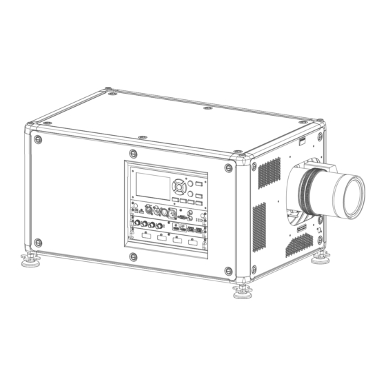
Input & Communication 6.1 Introduction General The Input & Communication module consists of a local keypad with LCD panel (1), a communication panel (4) and a Quad Combo input board (5). The free input slot can be used for optional modules (e.g. the Quad DP 1.2 input board). -
Page 65: Communication Connections
Input & Communication Local Keypad The Keypad gives direct access to several functions, in addition to access to the menu system. The keypad has a backlight that can be switched on and off manually. By default the light turns off after 5 minutes. - Page 66 Input & Communication You can use the DMX input port to connect a DMX device (DMX console) to the projector. This way you can control the projector from that DMX device (console). The DMX output port can be connected with the next device in the loop.
-
Page 67: Pulse Quad Combo Input Mk Ii
Input & Communication RS422 An EIA serial digital interface standard that specifies the electrical characteristics of balanced (differential) voltage, digital interface circuits. This standard is usable over longer distances than RS-232. This signal governs the asynchronous transmission of computer data at speeds of up to 920,000 bits per second. -
Page 68: Pulse Quad Combo Input Mk I
Input & Communication • If the source signal is connected to input A, connect input/output C to the Input of the following projector. • If the source signal is connected to input B, connect input/output D to the Input of the following projector. •... -
Page 69: Pulse Quad Dp 1.2 Input
Input & Communication • The SEL LED lit up GREEN when the input is selected. For specifications about the supported inputs for SDI, HDMI, HDBaseT and DisplayPort 1.2 see chapter “Video timing tables”, page 233. Remark concerning the Mk I and Mk II inputs boards The Mk I input board miss functionality that has been implemented on the Mk II input board. -
Page 70: Pulse Sfp Input
233. 6.7 Pulse SFP input The Barco SFP Input Board has been designed and tested to work alongside the Barco SFP Output Board. However, it is possible that the SFP Input board can also work with other third-party devices that support 12G over fiber. -
Page 71: Removal Of An Input Board
Input & Communication 6.8 Removal of an input board WARNING: The procedures below may only be performed by Barco trained and qualified technicians. CAUTION: Always wear a wrist band which is connected to the ground while handling the electrostatic discharge (ESD) sensitive parts. -
Page 72: Installation Of An Input Board
Input & Communication 6.9 Installation of an input board WARNING: The procedures below may only be performed by Barco trained and qualified technicians. CAUTION: Always wear a wrist band which is connected to the ground while handling the electrostatic discharge (ESD) sensitive parts. -
Page 73: Led And Button Indication Chart
Input & Communication 6.10 LED and Button indication chart Button Backlight Status Description Button Color status Standby button Blinking WHITE (slow) Projector starts up (booting) Blinking WHITE (fast) Firmware upgrade Solid WHITE Projector is in Standby mode Blinking BLUE Projector goes to ON mode Solid BLUE Projector is ON Blinking RED... - Page 74 Input & Communication R5906070 /16 HDX 4K...
-
Page 75: Wifi & Gsm Module
WiFi & GSM Module Compliance FCC ..........................76 Compliance IC..........................76 Installation of the WiFi module .......................77 Installation of the GSM module ......................80 Regulatory information for US and Canada can be accessed in the OSD of the projector. In order access it, select System Settings → Regulatory Information → Country. R5906070 /16 HDX 4K... -
Page 76: Compliance Fcc
WiFi & GSM Module 7.1 Compliance FCC Federal Communication Commission Interference Statement You are cautioned that changes or modifications not expressly approved by the part responsible for compliance could void the user's authority to operate the equipment. This equipment has been tested and found to comply with the limits for a Class A digital device, pursuant to Part 15 of the FCC rules. -
Page 77: Installation Of The Wifi Module
Cet appareil numérique de la classe A est conforme a la norme NMB-003 du Canada. 7.3 Installation of the WiFi module WARNING: The procedures below may only be performed by Barco trained and qualified technicians. CAUTION: Always wear a wrist band which is connected to the ground while handling the electrostatic discharge (ESD) sensitive parts. - Page 78 WiFi & GSM Module Image 7–1 Plug in the antenna wire connector on the WIFI module. Ensure to use bottom connection. Image 7–2 Place the WiFi module (2) upon the plastic socket (1). Note that the plastic socket is provided with two positioning pins which fits the small holes of the WiFi module.
- Page 79 WiFi & GSM Module Image 7–4 Install the data wire by plugging in the electrical connectors (connector J327, reference 1). Image 7–5 Position the antenna (7) in the hole on the front side of the Communication module. Secure the antenna wire by installing the lock washer and nut (8). Image 7–6 R5906070 /16 HDX 4K...
-
Page 80: Installation Of The Gsm Module
WiFi. For detailed instructions see user guide of the projector. 7.4 Installation of the GSM module WARNING: The procedures below may only be performed by Barco trained and qualified technicians. CAUTION: Always wear a wrist band which is connected to the ground while handling the electrostatic discharge (ESD) sensitive parts. - Page 81 WiFi & GSM Module Image 7–9 Overview GSM module RX Diversity antenna (DIV) Main RF antenna (ANT) Required tools Phillips screwdriver PH1 Required parts SIM card (not delivered) How to install Remove the Communication board. Remove the drive fastener (1) from the front side of the Communication module. Image 7–10 Slide in the SIM card into the SIM card holder (2).
- Page 82 WiFi & GSM Module Image 7–11 Plug in the antenna wire connector on the front side of the GSM module (4). Image 7–12 Insert the GSM module with antenna wire into the connector (5). Push the other side of the module down until it clicks so that the module is secured (6).
- Page 83 WiFi & GSM Module Image 7–14 Install the antenna by screwing it on its base (8). Stick the black label with certification numbers on the front plate of the communication board. Image 7–15 Example of the black label on the communication board Reinsert the communication board.
- Page 84 WiFi & GSM Module R5906070 /16 HDX 4K...
-
Page 85: Getting Started
Getting Started Power on projector........................86 Switching to standby ........................87 Power off projector........................88 Using the RCU ..........................88 Projector Address .........................89 Quick setup via Direct access ......................90 How controlling the projector ? The projector can be controlled by the local keypad, by the remote control unit or by browser application. Location of the local keypad ? The local keypad is located on the input side of the projector. -
Page 86: Power On Projector
Getting Started 8.1 Power on projector How to power on. Press the mains switch at the back of the projector to switch on this projector. Image 8–1 Main switch • When '0' is pressed, the projector is switched off. • When 'I' is pressed, the projector is switched on. -
Page 87: Switching To Standby
Getting Started • Current resolution and refresh rate • Device serial number and article number • Current firmware version and model name • Current illumination (in percentage) • Lamp runtime in hours • Chosen communication method and IP address (if connected) •... -
Page 88: Power Off Projector
Getting Started 8.3 Power off projector CAUTION: This procedure assumes the projector is in standby mode. How to power off Switch off the projector with the mains switch. '0' must be pressed. Image 8–5 Unplug the power cord from the projector. 8.4 Using the RCU Pointing to the reflective screen Point the front of the RCU to the reflective screen surface. -
Page 89: Projector Address
Getting Started Pointing directly to the IR sensor When using the wireless remote control, make sure you are within the effective operating distance (30 m, 100 ft in a straight line). The remote control unit will not function properly if strong light strikes the sensor window or if there are obstacles between the remote control unit and the projector IR sensor. -
Page 90: Quick Setup Via Direct Access
Getting Started The choice between '0' and '1' can be selected in the GUI: “System Settings” → “Communication” →“IR Control “. Placing new batteries in the remote control or plugging the remote to a projector via a cable will automatically reset the address back to its default value '0'. 8.6 Quick setup via Direct access Quick source selection Press the Input button on the remote control or local keypad. - Page 91 Getting Started Image 8–10 The Test pattern menu opens on the LCD display. Use the arrow keys to select the desired test pattern. R5906070 /16 HDX 4K...
- Page 92 Getting Started R5906070 /16 HDX 4K...
-
Page 93: Gui - Introduction
GUI – Introduction Overview .............................94 Navigation............................95 Test Patterns ..........................97 About this chapter This chapter gives an general overview of the Graphic User Interface. R5906070 /16 HDX 4K... -
Page 94: Overview
GUI – Introduction 9.1 Overview Disclaimer on GUI images used in this manual The GUI images in this manual are example illustrations and should be treated as such. While the name of the projector displayed in the illustrations may be different from the projector model you are currently using, the menu lay-out and functionality is identical. -
Page 95: Navigation
GUI – Introduction Image 9–2 Example of a Dashboard status screen GUI – Main Menu overview The projector on-screen display (OSD) is the primary user interface (UI). From here, you can review and adjust all projector and display settings. The OSD interface uses buttons to display the main menu. Each main menu contains submenus. The OSD can be disabled by pressing the OSD on/off button. - Page 96 GUI – Introduction Image 9–4 To start up the menu structure, press MENU (1). Use the arrow keys (Menu Navigation buttons) to navigate to the desired menu item (2). The background color changes to light blue. Press the Menu Selection button (center key of the arrow keys), also called OK button, to activate that item and to jump one level deeper (3).
-
Page 97: Test Patterns
GUI – Introduction To enter values with the local keyboard, use the arrow keys to select the first digit, press OK. Select the second digit and press OK. Continue until all digits are entered. Close the action by selecting the enter (↵) button and press OK. - Page 98 GUI – Introduction Image 9–7 Test patterns menu, test pattern off R5906070 /16 HDX 4K...
-
Page 99: Gui - Source
GUI – Source 10.1 Displaying a single source ......................100 10.2 Displaying multiple sources: Stitched layouts ................100 10.3 Connector Settings ........................102 About the Source menu This menu is used to select, review and configure sources into the projector. R5906070 /16 HDX 4K... -
Page 100: Displaying A Single Source
GUI – Source 10.1 Displaying a single source About selecting a source Before a source can be projected, the source signal must be connected to the source input(s) of the device and a valid synchronization signal must be available along with the source signal on at least one of the input connectors. - Page 101 GUI – Source The table below describes the different Stitch Layouts and scan directions. Type of layout Description Available connectors Mode A single source is displayed in Quad Combo input: Mono / Active full screen stereo • SDI (4x) • HDBaseT (2x) •...
-
Page 102: Connector Settings
GUI – Source Image 10–4 Example of the stitched layout options Select the desired stitched input. Tip: If the Quad DP input board is installed, scroll all the way down the menu for the stitched options on that board. Image 10–5 Example of the stitched input options with the Quad DP board installed 10.3 Connector Settings About Connector Settings The Connector Settings menu allows you to change settings for each input connector of the projector. - Page 103 GUI – Source Image 10–6 Main menu, Source Press OK. The Select Source menu is displayed with the actual available sources filled out. Scroll down to the bottom of the list of available sources and select Connector Settings. Image 10–7 Source menu, connector settings The available input connectors are displayed.
- Page 104 GUI – Source Image 10–9 Example of connector settings for an HDMI connector You can change the following: • To force a limit on the used signal range, select one of the available signal ranges. • To force a limit on the color space, select one of the available color spaces. •...
-
Page 105: Gui - Image
GUI – Image 11.1 Setting image levels manually...................... 106 11.2 Adjusting the sharpness ......................107 11.3 Adjusting the gamma correction....................108 11.4 Setting the desired Gamma type ....................109 11.5 RealColor P7..........................111 11.6 Setting the output resolution ......................113 11.7 Displaying HDR content ...................... -
Page 106: Setting Image Levels Manually
GUI – Image 11.1 Setting image levels manually Purpose Contrast: Change the contrast of the complete output signal (main and PiP window together) of the projected image. Brightness: Change the brightness of the complete output signal (main and PiP window together) of the projected image. -
Page 107: Adjusting The Sharpness
GUI – Image Image 11–4 Example of the image sliders, brightness is the second slider If necessary, use the ▲ or ▼ key to select the other image adjustment options. How to set up Saturation Level In the main menu, select Image → Saturation. Image 11–5 Image menu —... -
Page 108: Adjusting The Gamma Correction
GUI – Image Increasing the sharpness will have the best effect in high contrast images, eg a table with text and borders. In a natural picture, high sharpness can be perceived as noise, as all details in the picture will be amplified. Available range: -2 to 8. -
Page 109: Setting The Desired Gamma Type
GUI – Image Image 11–10 Image menu – Gamma Use the ▼ key to select the slider. Use the ◄ or ► key to change the gamma value between 1.0 and 2.8 . The default value is 2,2. Tip: The slider can be adjusted with a precision of 0.1. Image 11–11 Example of the gamma menu 11.4 Setting the desired Gamma type Exception when using an HDR source... - Page 110 GUI – Image How to adjust the gamma type? In the main menu, select Image → Gamma type. Image 11–13 Image menu – Gamma The Gamma type menu is displayed. If source content is available, the detected gamma of the source will be displayed at the bottom of the menu.
-
Page 111: Realcolor P7
GUI – Image 11.5 RealColor P7 Purpose When blending images from multiple projectors, the perceived color coordinates of each projector can be altered to a desired common level, so that the projected colors are identical over all projectors used. Alternatively, if you are unfamiliar with how adjusting the Colors to a specific setting, there are also a certain number of presets available, which forces the color output to specific color standards. - Page 112 GUI – Image You can reset all coordinates to the default values (to native) by clicking the Reset icon. How to choose one of the P7 presets In the main menu, select Image → Advanced → P7 Realcolor. Image 11–18 Advanced settings menu – RealColor P7 The P7 menu is displayed.
-
Page 113: Setting The Output Resolution
GUI – Image Note: After choosing one of the presets, you can still alter the values of the coordinates to your own choosing, similarly to how you set custom P7 values. Use the Reset icon to return to the default values of the chosen preset. 11.6 Setting the output resolution This menu is only available on the 4k models, with an actuator included. -
Page 114: Displaying Hdr Content
GUI – Image • 4K UHD S: 4k extra sharp images, using the actuator at a higher frequency • WQXGA: 2k images. In this mode, the actuator is disabled. 11.7 Displaying HDR content About HDR and PQ Perceptual Quantizer (PQ) is a non–linear electro-optical transfer function (EOTF) that allows for the display of High Dynamic Range (HDR) content with a luminance level of up to 10 000 cd/m²... - Page 115 GUI – Image The HDR menu is displayed. Image 11–25 Example of the HDR menu Select the desired Screen luminance unit (nits or foot-Lambert). Enter the Screen luminance (which is measured in nits or foot-Lambert). Alter the HDR boost if necessary. You can modify this value to somewhere between 0.8 and 1.2. R5906070 /16 HDX 4K...
- Page 116 GUI – Image R5906070 /16 HDX 4K...
-
Page 117: Gui - Installation
GUI – Installation 12.1 Configuring the lens, optical zoom-focus ..................118 12.2 Configuring the lens, shift ......................118 12.3 Configuring the lens, dynamic focus ..................... 119 12.4 Configuring the lens, Shift to center....................120 12.5 Configuring the lens, tilt sensor ....................120 12.6 Manipulating the rigging frame .................... -
Page 118: Configuring The Lens, Optical Zoom-Focus
GUI – Installation 12.1 Configuring the lens, optical zoom-focus What can be done? If a motorized lens has been mounted onto the projector, you can fine-tune the projected image. Zoom - Focus In the main menu, select Installation → Lens → Zoom focus. Image 12–1 Lens menu, Zoom &... -
Page 119: Configuring The Lens, Dynamic Focus
GUI – Installation Image 12–4 Example of the lens shift menu Use the ◄ and ► keys to shift the lens (image) in horizontal direction. Use the ▲ and ▼ keys to shift the lens (image) in vertical direction. 12.3 Configuring the lens, dynamic focus About focus drift and dynamic focus Due to the design of ultra-short throw lenses (UST lenses), this type of lens tends to heat up over time when used in projectors. -
Page 120: Configuring The Lens, Shift To Center
GUI – Installation Image 12–6 Lens menu, Image 12–7 Lens menu, Dynamic focus enabled Dynamic focus disabled Note: The Dynamic focus slider is only visible when the light source is on. 12.4 Configuring the lens, Shift to center What can be done? The lens can be forced back to the center position by selecting Shift to center. -
Page 121: Manipulating The Rigging Frame
GUI – Installation Image 12–9 Lens menu, Tilt sensor The Tilt sensor menu is displayed. Image 12–10 Example of the tilt sensor menu If you notice the tilt sensor isn’t working correctly (e.g. when compared to a level), you can calibrate the sensor in the settings menu. - Page 122 GUI – Installation Image 12–12 Example of the Motorized frame menu Press the OK key or button to activate the frame shift motors. Image 12–13 Example of horizontal and vertical frame shift Use the ▲ or ▼ button to shift the rigging frame (image) in vertical direction. Use the ◄...
-
Page 123: Manipulating The Rigging Frame, Center Position
GUI – Installation Confirm with the OK button to return to the frame shift menu, or use the Menu back button to return to the Lens menu. 12.7 Manipulating the rigging frame, center position What can be done? The motorized frame can be forced back to the center position by selecting Center motorized frame. How to reset the motorized frame? In the main menu, select Installation →... -
Page 124: Scaling Modes
GUI – Installation • Auto front: The projector detects itself if it is ceiling or table mounted and projects always a readable image. • Auto rear: The projector detects itself if it is ceiling or table mounted and projects always a readable image. How to set the correct orientation In the main menu, select Installation →... - Page 125 GUI – Installation Scaling Mode Explanation Example image Fill aspect Default scaling mode. Stretches the image to the native resolution of the DMD, while respecting the original aspect ratio. An exact rendering of the source signal, which may be smaller than the native resolution Fill screen Fills the screen to the screen size defined in the Screen Size menu, while respecting the original aspect ratio.
-
Page 126: Warping
GUI – Installation Image 12–20 Example of the scaling mode menu In the Scaling menu, select the desired scaling mode and confirm. 12.10 Warping About warping Image warping is the process of digitally manipulating an image to compensate for the distortion of the screen. Consequently, it can also be used to generate an image with irregular shape. -
Page 127: Warping - Screen Size
GUI – Installation Image 12–22 Example of the Warp menu In the Warp menu, click Warp to toggle between On and Off. Image 12–23 Image 12–24 12.10.2 Warping – Screen Size About (Warp) Screen Size adjustment If the used source aspect ratio is different than the projector aspect ratio, e.g. source is 16:9 and projector is 16:10, then black bars will be projected. - Page 128 GUI – Installation Image 12–26 Warp menu, screen size The Screen Size menu is displayed. Image 12–27 Example of the screen size menu Select either Screen width or Screen height. Set the new value to shrink either the width or height of the warp outline so that the outline is equal with the active source.
-
Page 129: Warping - 4 Corners Adjustment
GUI – Installation 12.10.3 Warping – 4 corners adjustment About 4 Corners adjustment 4 corner adjustment is typically used when the mechanical installation of the projector prevents it from pointing perpendicularly at the screen. For example, you can overshoot the screen and use 4 corner adjustment to pull your projected image corners back into the screen. -
Page 130: Warping - Bow
GUI – Installation Image 12–32 Example of 4 corners warping menu, with helper lines active on the edges of the screen To set warping on one of the four corners, select one of the four corners and confirm. Set the desired X and Y coordinates for this corner, using the arrow keys, and confirm. After confirming, the helper lines for that corner will jump to the entered XY coordinate (if helper lines were enabled). - Page 131 GUI – Installation Image 12–34 Bow distortion Definition of angle and linearity (length) in the bow warp procedure Image 12–35 Symmetric bow correction In the main menu, select Installation → Warp → Bow. Image 12–36 Warp menu, Bow The bow menu is displayed. To enable bow correction, make sure the Bow slider is enabled (visible by the blue highlight).
- Page 132 GUI – Installation Image 12–37 Both the Bow and Symmetric sliders are set to on Use the arrow keys to select the helping lines that represent the picture and confirm. The helping lines that represent the projected picture are now colored blue, while the others are colored white.
- Page 133 GUI – Installation The correction will occur symmetrically on each side of the center of the highlighted side. Repeat this step for all sides of the picture that has to be corrected, until the desired transformation has been achieved. Image 12–40 Example of a symmetric bow correction Asymmetric bow correction In the Bow menu, enable the Bow slider and disable the symmetric slider.
- Page 134 GUI – Installation Image 12–42 Select the desired slider and confirm. Image 12–43 Adjust angle and linearity (length) individually to obtain the correct correction. Press enter to confirm and to switch between angle and length. Tip: Adjust the angle by using the up and down arrow keys. Adjust the linearity by using the left and right arrow keys.
-
Page 135: Warping - Warp Files
GUI – Installation To reset the bow adjustments, select Reset and confirm. 12.10.5 Warping – Warp files About custom Warp Files Next to setting your specific warp configuration in the GUI, you can also upload or download a custom warp grid in XML format to/from the projector. -
Page 136: Warping - Latency Control In A Multi Projector Setup
GUI – Installation Image 12–47 Example of the Warp files menu Make sure the Enable slider is set to right. Select the desired warp file. Image 12–48 Example of the Warp files menu 12.10.6 Warping – Latency control in a multi projector setup Transport latency The added delay in the image processing chain. - Page 137 GUI – Installation Image 12–49 Example of the Transport delay in the status menu Identify the projector with the longest delay. For each projector in the setup, select Installation → Warp in the main menu. Image 12–50 Installation menu, Warp In the Warp menu, select Transport Delay.
-
Page 138: Blending & Masking
GUI – Installation Click “Apply” to confirm the value. Repeat this process for every projector in the setup. 12.11 Blending & masking About blending Blending is used in multi channel installation to have a seamless transition between the channels. Image blending gives the appearance of a single view, thus achieving realistic immersion for the majority of wide screen applications. - Page 139 GUI – Installation Image 12–55 Example of the basic blend menu To enable blending, put the Enable switch to the right. The color of the switch becomes blue when enabled. To project masking lines on the screen, put the Show lines switch to the right. The color of the switch becomes blue when enabled.
-
Page 140: Blend & Blend Mask
GUI – Installation Do not forget to disable the Show lines button after you achieved the desired blend zone. 12.11.2 Blend & Blend mask About masking and blending width or height Offset is used to clip the image on one or multiple sides (masking). This is used to hide parts of the picture that should not be shown on the screen. - Page 141 GUI – Installation Image 12–59 Start position (mask) Blending width Select one of the four starting positions values with the arrow keys and confirm. Use the arrow keys or remote digits to change the value of the mask and confirm. Repeat this process for all other desired sides.
-
Page 142: Blend Files
GUI – Installation Image 12–60 Set up for projector 1 Image 12–61 Set up for projector 2 12.11.3 Blend Files About custom Blend Files Next to setting your specific Blending configuration in the GUI, you can also upload or download a custom Blend configuration file in png, jpg or tiff format to/from the projector. -
Page 143: Basic Black Level Adjustment
GUI – Installation Image 12–62 Blend and mask menu, Blend files The Blend Files menu is displayed. Image 12–63 Example of the blend files menu If any custom Blend files are available, select the desired file. Image 12–64 To enable the selected blend file, make sure the Enable slider is set to the right. The color of the slider becomes blue when enabled. - Page 144 GUI – Installation You can also specify the offsets manually by turning off the automatic calculation. The black level value is adjusted in a 16–bit resolution from 0 to 65535. The following figure shows how this occurs in a side by side configuration without any correction of the black level.
-
Page 145: Rgb Gain Adjustment
GUI – Installation Move the cursor to Level, press enter and adjust this level until the black level equals the level in the blend zone. This value can also be entered by the numeric keys on the remote control. Repeat the same procedure for any other projector connected to this projector, but on the opposite side. Note: Do not forget to disable the Show lines button after you achieved the desired blend zone. -
Page 146: Black Level Files
GUI – Installation Image 12–70 Example of the default black level menu Select one of the three sliders on the bottom of the menu (Red, Green or Blue). Use the left and right arrow keys to modify the gain of the chosen color. Repeat for every slider until the desired result is achieved on screen. -
Page 147: Z-Axis Calibration
GUI – Installation Image 12–72 Example of the black level files menu If any custom Black Level adjustment files are available, select the desired file. Image 12–73 Example of custom black level files selected Make sure the Enable slider is set to the right to activate the selected black level file 12.12 Z-Axis Calibration What can be done? The Z-Axis menu item gives the current light output of the projector (in percentage). -
Page 148: Illumination
GUI – Installation Image 12–74 Installation menu, Z-axis calibration The Z-axis calibration menu is shown. Image 12–75 Example of the Z-axis calibration menu Enable Show test pattern. While you perform the actual Z-axis calibration, leave this menu open. While this menu is open, a white test pattern is projected and the current light output is indicated in the menu. -
Page 149: Projection
GUI – Installation Image 12–76 Installation menu, illumination The Illumination menu is displayed. Image 12–77 Example of the Illumination menu Use the Slider to change the power value. Enable the Constant light output slider if you want to enable CLO mode. If CLO mode is active, you can use the CLO Scale slider to scale the light output. -
Page 150: Setup Process 3D Projection
GUI – Installation What is Active Stereo? Field sequential 3D (also known as active 3D or “Active Stereo”) is a technique of displaying stereoscopic 3D images. It works by only presenting the image intended for the left eye while blocking the right eye's view, then presenting the right-eye image while blocking the left eye, and repeating this so rapidly that the interruptions do not interfere with the perceived fusion of the two images into a single 3D image. -
Page 151: Setup
Why change the 3D setup? While Barco can provide a 3D emitter and active shutter glasses as options to this projector, you are also free to use a 3D emitter and active shutter glasses of your own choice. Since glasses and emitter can have various specifications compared to the ones Barco can provide, the 3D setup menu allows you to configure the output image to the specifications of your glasses and emitter. - Page 152 GUI – Installation If a 3D emitter is used that radiates infrared beams (IR beams), the IR beams may interfere with the IR communication between projector and the RCU. If such interference occurs, connect the RCU to the projector using the remote cable. It is also advised to turn the IR receivers on the projector off to avoid the 3D emitter interference.
-
Page 153: Gui - Macro's And Projector Profiles
GUI – Macro’s and projector profiles 13.1 Saving the current projector settings in a profile ................154 13.2 Assigning a created projector profile to a preset ................156 13.3 Deleting a projector profile......................157 About macro’s and projector profiles Projectors can have different settings, depending on different environments (e. g. playing video games in a bright environment or playing a movie in a dark environment), or using different mediums (e.g. -
Page 154: Saving The Current Projector Settings In A Profile
GUI – Macro’s and projector profiles 13.1 Saving the current projector settings in a profile Which settings can be saved to a profile? Profile setting Settings saved name Source Active source selection & EDID Image • All basic image settings: contrast, brightness, saturations, sharpness & gamma •... - Page 155 GUI – Macro’s and projector profiles Image 13–1 Profiles menu, edit The Profile edit menu is displayed. Image 13–2 Profile edit menu Use the arrow keys to select New Profile... and confirm. The New Profile pane is expanded and fully displayed. Image 13–3 Example of the new profile pane Use the arrow keys and the okay key to select any of the settings you wish to save in this macro.
-
Page 156: Assigning A Created Projector Profile To A Preset
GUI – Macro’s and projector profiles 13.2 Assigning a created projector profile to a preset This procedure assumes you have created at least one projector profile. For more info on saving projector settings to a profile, see “Saving the current projector settings in a profile”, page 154. -
Page 157: Deleting A Projector Profile
GUI – Macro’s and projector profiles The preset slot is now shown next to the profile name. Image 13–7 Example of projector profiles allocated to preset slots (here slot 00 and 04) 13.3 Deleting a projector profile How to delete a profile In the main menu, select Profiles →... - Page 158 GUI – Macro’s and projector profiles Image 13–10 Example of a projector profile with available preset slots Use the arrow keys to select Delete and confirm. confirm the delete action. R5906070 /16 HDX 4K...
-
Page 159: Gui - System Settings
GUI – System Settings 14.1 Communication, LAN setup ......................160 14.2 IR control ........................... 166 14.3 Setting a custom projector name....................169 14.4 DMX ............................169 14.5 Front XLR output voltage control....................171 14.6 GSM configuration........................172 14.7 Changing the User Interface language ..................173 14.8 Themes ............................. -
Page 160: Communication, Lan Setup
GUI – System Settings 14.1 Communication, LAN setup About a network connection A network connection can be made via a wired connection or via the optional wireless unit. 14.1.1 Introduction to a Network connection DHCP Dynamic host configuration protocol. DHCP is a communications protocol that lets network administrators manage centrally and automate the assignment of IP addresses in an organization's network. - Page 161 GUI – System Settings Image 14–1 Communication menu, LAN The LAN menu is displayed. Image 14–2 Example of the LAN menu To enable Automatic, make sure the Automatic slider is set to the right. The color of the slider will be blue. An IP address will be automatically assigned if it can make a connection to the network..
-
Page 162: Wireless Ip Address Set Up
GUI – System Settings Image 14–4 Example of the LAN menu Disable the Automatic slider. The slider becomes gray. Use the arrow keys to select Address and press OK button to activate the input box. Image 14–5 Example of entering the IP address Use the arrow keys and enter key to enter in the IP address. - Page 163 GUI – System Settings Image 14–6 Communication menu, WiFi The WiFi menu is displayed. Image 14–7 Example of the WiFi menu Make sure the Enable slider is set to the right to enable the WiFi module. The color of the slider becomes blue.
- Page 164 GUI – System Settings Tip: If the desired wireless network is not in the list or hidden by default, select Other network. A form will pop up, allowing you to fill in the details of the network. Image 14–9 Example of the entry form to search for other wireless networks If required by the chosen wireless network fill in the user name, password and confirm.
- Page 165 GUI – System Settings Image 14–11 Example of the WiFi menu Make sure the Enable slider is set to the right to enable the WiFi module. The color of the slider becomes blue. Disable the Automatic slider by setting it to the left. The switch becomes gray. Image 14–12 Use the arrow keys to select Address and press OK button to activate the input box.
-
Page 166: Ir Control
GUI – System Settings Image 14–13 Example of the available networks list. Press Connect to connect to the selected network. If required by the chosen wireless network, fill in the username and password and confirm. When connected to this network, it is indicated in the upper right corner of the menu with the term “connected”. -
Page 167: Projector Address
The following choices are possible: • Generic IR (address 0) • Barco broadcast IR (address 1) Select APPLY and click OK to apply the changes. 14.2.2 Projector address About individual projector address As more than one projector can be installed in a room, each projector should be separately addressable with an RCU or with a computer using serial communication. -
Page 168: Ir Sensors
GUI – System Settings Image 14–17 Example of the IR control menu Select the current projector address and enter a new address. Select APPLY and click OK to apply the changes. From now on the projector will only listen to this new address and to its broadcast address. 14.2.3 IR sensors What can be done? Each IR sensor can be individually disabled or enabled. -
Page 169: Setting A Custom Projector Name
GUI – System Settings To disable an IR sensor, select the slider and drag to the left. A blue slider means an active IR sensor. A gray slider means an inactive IR sensor. Select APPLY and click OK to apply the changes. 14.3 Setting a custom projector name What can be done? The default name of the projector is “Pulse”. - Page 170 GUI – System Settings If you are using a DMX console and other automated lighting products compatible with Art-Net, the Ethernet network can serve as the link for DMX control. All DMX controls can be sent over the Ethernet cable. Multiple universes are possible.
-
Page 171: Front Xlr Output Voltage Control
GUI – System Settings Image 14–23 Example of the DMX menu Choose the desired DMX mode. Choose the desired starting channel. Choose whether or not you want the Auto power-down feature to be enabled. If enabled, determine the time-out. If required, enable Art-Net. If enabled, determine the desired Art-Net Universe and Art-Net channel. If a front XLR connector is available on your projector, you can enable the output voltage on this connector. -
Page 172: Gsm Configuration
GUI – System Settings Image 14–25 Example of the DMX menu On the bottom of the DMX menu, Enable the XLR connector slider. Select the desired Output Voltage. 14.6 GSM configuration Only possible when a GSM module with SIM card is installed in the projector. What can be done ? To configure the projector software with the installed SIM card, a correct PIN code (4digits) must be entered. -
Page 173: Changing The User Interface Language
GUI – System Settings Image 14–27 Example of the GSM menu once the pin code has been applied 14.7 Changing the User Interface language How to change the language of the user interface In the main menu, select Settings → User interface → Language. Image 14–28 Interface The Language menu is displayed. -
Page 174: Themes
GUI – System Settings • Chinese (ZH) 14.8 Themes About Themes Themes are used to apply a predefined functionality to the OSD display. There are two options: light or dark (default). While the default theme is dark, all images in this manual are taken while using the light theme. How to select a different interface theme In the main menu, select Settings →... -
Page 175: Controlling The Backlight Of The Lcd Display
GUI – System Settings Image 14–32 Example of the Units menu Select the desired Temperature unit and Length unit and confirm. 14.10 Controlling the backlight of the LCD Display What lighting can be controlled? You can choose how quickly the backlight of the LCD turns off. You can select one of the default values, or enter a custom value. -
Page 176: Power Settings
GUI – System Settings Image 14–34 Example of the backlight menu Choose the desired setting for the backlights. Select one of the predetermined options, or a custom value. 14.11 Power settings Why change the power saving features? As a power-saving feature, the projector will automatically go to Ready and standby mode after 15 minutes each. -
Page 177: Lens Features
GUI – System Settings Image 14–36 Example of the power settings menu To change the time the projector turns the light source off, select the desired Power off time-out. To change the time the projector goes to stand-by mode, select the desired Standby time-out. How to disable/enable auto off mode In the main menu, select Settings. -
Page 178: Factory Reset
GUI – System Settings Image 14–39 Settings menu, Lens features The Lens features menu is displayed. Image 14–40 Example of the lens features menu Depending on the mounted lens type, different functions may or may not be available such as: •... - Page 179 GUI – System Settings Option Setting Factory setting Image connectors Color Space auto Signal Range auto Image convergence Electronic Convergence All values to zero Image display Display mode AutoStereo Image features Contrast mid value Brightness mid value Saturation mid value Sharpness mid value Gamma...
- Page 180 GUI – System Settings Option Setting Factory setting Units – Temperature °C Units – Length Meters (m) How to reset all projector settings In the main menu, select Settings → Maintenance → Reset. Image 14–41 Settings menu, factory reset The Reset menu is displayed. Image 14–42 Example of the reset menu In the Reset menu, select RESET ALL and confirm with OK.
-
Page 181: Lens Calibration
GUI – System Settings Image 14–44 Example of the reset menu Navigate to the checkbox next to the settings that need to be reset and press OK. Multiple selections are possible. Select RESET SELECTED and confirm with OK to reset all selected settings. 14.14 Lens Calibration How to calibrate In the main menu, Settings →... -
Page 182: Flex Brightness
GUI – System Settings • Focus • Zoom The text Calibrating will be displayed in the icon of the selected function until the calibration is completed. Image 14–47 example of calibration in progress When an error is detected, the message Calibration Error is displayed next to function. 14.15 Flex brightness This feature is available by default on the following devices: N.A.. - Page 183 GUI – System Settings How to configure? Create a new text message containing 3 parts, each separated with a space character: • Activation code (created using Projector Toolset) • Action string • Action parameter Example: “1234 MLO 14” Send this message to the GSM number associated with the projector. The receiving projector will analyze the message and configure the light output accordingly.
-
Page 184: Electronic Convergence
GUI – System Settings Image 14–50 Example of entering the code in the Flex license menu 14.16 Electronic Convergence What can be done? The convergence patterns can be used to check the convergence alignment of red, green and blue. If there is a misalignment of at least one 1 pixel, an electronic realignment is possible. -
Page 185: List Of Open Source Licenses
GUI – System Settings Confirm all changes by pressing Enter. Image 14–53 Tip: Press Reset to return all values to the factory settings. Repeat all steps until the desired alignment is achieved. 14.17 List of open source licenses About open source licenses Open source licenses are licenses that comply with the Open Source Definition. -
Page 186: Remote Access - Enable Source Preview
GUI – System Settings It doesn’t matter what else you do or type with the remote. As long as you type in the service code in the correct order, the Advanced Settings option will become visible. Image 14–55 Example of the Maintenance menu, with the Advanced menu and Remote access menu unlocked The Advanced Settings and Remote access menu items will remain visible until you leave the Maintenance menu. -
Page 187: Remote Access - Enable Camera Preview
GUI – System Settings Image 14–57 Example of the Remote access menu Enable the slider to enable the source preview feature. Image 14–58 Remote access menu, Source preview is enabled 14.18.2 Remote access – Enable camera preview Camera preview Up until Pulse software 2.0.x, you were able to see the footage of the camera when you remotely accessed the projector. -
Page 188: Advanced Settings - Color
GUI – System Settings Image 14–60 Example of the Remote access menu Enable the slider to enable the Camera preview feature. Image 14–61 Remote access menu, Camera preview is enabled 14.18.3 Advanced Settings – Color CAUTION: The native colors have been measured and set during factory production. Do not change them, unless parts of the optical path have been replaced due to servicing. -
Page 189: Advanced Settings - Statistics
GUI – System Settings The RealColor calibration menu will be displayed. Image 14–64 Example of the RealColor calibration menu Select the desired value to change and confirm. Change the values to the desired position, taking into account the color gamut values. Select APPLY and confirm. -
Page 190: Advanced Settings - Tilt Sensor Calibration
GUI – System Settings The Statistics will be displayed. Image 14–67 Example of the statistics menu 14.18.5 Advanced settings – Tilt sensor calibration CAUTION: The calibration procedure resets the values of the tilt sensor to 0 in the current position of the projector. - Page 191 GUI – System Settings Image 14–70 Example of the Advanced menu with the Tilt sensor menu The tilt sensor will be set to zero in the current position of the projector. R5906070 /16 HDX 4K...
- Page 192 GUI – System Settings R5906070 /16 HDX 4K...
-
Page 193: Gui - Status Menu
GUI – Status menu 15.1 Status menu overview......................... 194 No settings can be modified in the status menu. Its only for consulting. R5906070 /16 HDX 4K... -
Page 194: Status Menu Overview
GUI – Status menu 15.1 Status menu overview How to access the status menu While in the main menu, press Status. Image 15–1 Main menu, status The status menu is displayed. Image 15–2 Example of a status menu Swipe the screen to switch between the Status and About page. Image 15–3 Example of the About page in the Status menu What can be seen on the Status page? •... - Page 195 GUI – Status menu What can be seen on the About page? • Projector information, e.g. firmware version, serial number and projector article number • Mounted lens: Type and description • Basic statistics, e.g. light source run time, projector runtime R5906070 /16 HDX 4K...
- Page 196 GUI – Status menu R5906070 /16 HDX 4K...
-
Page 197: Projector Maintenance
Projector maintenance 16.1 Software update ......................... 198 16.2 Cleaning the lens........................199 16.3 Cleaning the exterior of the projector .................... 200 About this chapter This chapter contains general maintenance procedures. R5906070 /16 HDX 4K... -
Page 198: Software Update
Download the latest firmware (format .fw) from Barco's website in the same way as for Projector Toolset. Start Projector Toolset and make a connection with the projector. For more information, see the “Projector Toolset”... -
Page 199: Cleaning The Lens
Always contact Barco if you want to make sure a downgrade will not hurt your device. -
Page 200: Cleaning The Exterior Of The Projector
Projector maintenance Use a dry lens cleaning cloth to remove left liquid or stripes. Polish with small circles. If there are still fingerprints on the surface, wipe them off with lens cleaner together with a clean lens cleaning cloth. Polish again with a dry one. If smears occur when cleaning lenses, replace the cloth. -
Page 201: Servicing
These procedures may only be performed by qualified technical service personnel. Extra service information Extra service information for qualified service technicians can be found on Barco's Partnerzone (URL: http:\\www.barco.com). Registration is necessary. If you are not yet registered, click on Partnerzone registration and follow the instructions. With the created login and password, it is possible to enter the partnerzone where you can find extra service information about the projector. -
Page 202: Removal Of The
Servicing 17.1 Removal of the front cover WARNING: Switch off the projector and unplug the power cord before starting the procedure. Required tools 7 mm flat screw driver How to remove Remove the lens. See “Lens removal”, page Remove the rubber dust ring from the lens holder. Image 17–1 Dust ring removal Release the 4 captive screws (1). -
Page 203: Mounting The
Servicing Image 17–2 Front cover removal Take off the front cover. 17.2 Mounting the front cover WARNING: Switch off the projector and unplug the power cord before starting the procedure. Required tools 7 mm flat screw driver How to mount Place the front cover with the rubber dust facing the projector on its place. - Page 204 Servicing Image 17–3 Mount front cover Secure the 4 captive screws (1). Reinstall the rubber dust ring around the lens holder. Image 17–4 Mount dust ring Mount lens again. R5906070 /16 HDX 4K...
-
Page 205: Removal Of The Lamp Cover
Servicing 17.3 Removal of the lamp cover WARNING: Switch off the projector and unplug the power cord before starting the procedure. Required tools 7 mm flat screw driver How to remove Release the 6 captive screws. Image 17–5 Lamp side cover Take off the side cover. -
Page 206: Removal Of The Lamp House
Servicing Image 17–6 Lamp side cover 17.5 Removal of the lamp house WARNING: Switch off the projector and unplug the power cord before starting the procedure. WARNING: The Lamp House is very hot after operation. Let the projector cool down for at least 15 minutes before proceeding to the next step. -
Page 207: Installation Of The Lamp House
Servicing Image 17–7 Lamp house, captive screws Take the lamp house by both handles and pull it out. Image 17–8 Lamp house, removal 17.6 Installation of the lamp house WARNING: Switch off the projector and unplug the power cord before starting the procedure. Required tools Flat screwdriver R5906070 /16... -
Page 208: Replacement Of The High Density Dust Filter
Servicing How to install Take the lamp house by its handles and gently slide the lamp house into its socket. Note that the compartment is provided with a guide (1) to position the lamp house correctly. Image 17–9 Insert lamp house Push the lamp house forward until it slides fully into the projector. -
Page 209: Remove And Clear Metal Front Filter
Servicing Required parts New filter (available kit : R98010085, contains 5 high density filters and one cleanable filter) How to replace Remove the front cover, see “Removal of the front cover”, page 202. Push both filter holders to the outside. Image 17–10 Filter replacement Take out the filter and insert a new one. - Page 210 Servicing Image 17–11 At the same time, take out the filter. Clean the dust filter Remove most contamination with a vacuum cleaner. Blow remaining dust away with compressed air in an other room or outside. If you cannot clean the filter anymore, insert a new one. How to install Pull the bottom holder to the front and insert the filter.
-
Page 211: A Specifications
Specifications Specifications of the HDX-4K12 ....................212 Specifications of the HDX-4K14 ....................213 Specifications of the HDX-4K20 FLEX..................215 Dimensions of a HDX........................217 Technical Regulations ......................... 217 About this chapter This chapter gives an overview of the specification of the HDX projector as well as the dimensions and the center of gravity. -
Page 212: Specifications Of The Hdx-4K12
Specifications A.1 Specifications of the HDX-4K12 Specifications Projector type 4K UHD 3-Chip DLP digital projector Technology 0.90" DMD x 3 with sealed DMD core Resolution 3,840 x 2,400 (4K UHD) / 2,560 x 1,600 (WQXGA native) / 16:10 aspect ratio Light output 11,000 (WQXGA) / 10,200 (4K UHD mode) center lumens* Contrast ratio... -
Page 213: Specifications Of The Hdx-4K14
Compliant with UL60950-1 and EN60950-1, complies with FCC rules & regulations, part 15 Class A and CE EN55022 Class A, RoHS Warranty 3 years standard +/- 10% SW upgradable. Please contact an authorized Barco representative for details. A.2 Specifications of the HDX-4K14 Specifications Projector type... - Page 214 Compliant with UL60950-1 and EN60950-1, complies with FCC rules & regulations, part 15 Class A and CE EN55022 Class A, RoHS Warranty 3 years standard +/- 10% SW upgradable. Please contact an authorized Barco representative for details. R5906070 /16 HDX 4K...
-
Page 215: Specifications Of The Hdx-4K20 Flex
Specifications A.3 Specifications of the HDX-4K20 FLEX Specifications Projector type 4K UHD 3-Chip DLP digital projector Technology 0.90" DMD x 3 with sealed DMD core Resolution 3,840 x 2,400 (4K UHD) / 2,560 x 1,600 (WQXGA native) / 16:10 aspect... - Page 216 Certifications Compliant with UL60950-1 and EN60950-1, complies with FCC rules & regulations, part 15 Class A and CE EN55022 Class A, RoHS Warranty 3 years standard SW upgradable. Please contact an authorized Barco representative for details. R5906070 /16 HDX 4K...
-
Page 217: Dimensions Of A Hdx
Specifications A.4 Dimensions of a HDX Overview Center of gravity Center of gravity Image A–1 Dimensions, mm Geometrical centre Centre without lens Centre with lens 186.5 170.0 185.0 237.5 241.0 248.0 362.5 370.0 330.0 A.5 Technical Regulations Certificates Image A– Image A–... - Page 218 Specifications R5906070 /16 HDX 4K...
-
Page 219: B Stacking Hdx Projectors
Stacking HDX projectors Mount stacking points ......................... 220 Stacking HDX projectors ......................220 Aligning stacked HDX projectors....................223 R5906070 /16 HDX 4K... -
Page 220: Mount Stacking Points
Stacking HDX projectors B.1 Mount stacking points Required tools Allen key 8 mm How to mount Place the first stacking point on a corner. Image B–1 Stacking points, mount Turn in the delivered bolt. Repeat for the other 3 stacking points. B.2 Stacking HDX projectors CAUTION: Maximum stack three (3) projectors in a table mounted configuration. - Page 221 Stacking HDX projectors Image B–2 Dual stack Tip: In case of stacking projectors for a ceiling mount configuration, first turn the projectors upside down before placing the projectors on top of each other. Attach the two projectors together by closing all four interlocking adapters. Image B–3 Interlocking, close Extra actions for ceiling mounted stack Two safety cables must be mounted between both projectors, one at each longitudinal side.
- Page 222 Stacking HDX projectors Image B–4 Security cables, mount Mount the other end of the security cable around the carry handle of the top projector and clasp the safety hook round the cable as illustrated. Make sure that the falling distance is maximum 20 cm. If necessary, before clasping the safety hook around the cable, turn the cable a few time around the carry handle.
-
Page 223: Aligning Stacked Hdx Projectors
Stacking HDX projectors WARNING: Never open an interlocking adapter of a stacked projector which is still suspended. First place the stacked projectors on the floor. B.3 Aligning stacked HDX projectors Required tools No tools required. How to align stacked projectors Make sure that the internal hatch pattern projected by the reference projector is sharp and has a perfect rectangle outline. - Page 224 Stacking HDX projectors Inclination Image B–7 Stacked projectors, inclination If necessary, adjust the skew of the stacked projector with respect to the reference projector by turning the Hand screw in or out. The hand screw is located at smallest side of the carrying handle (front or back). Adjust until the outline of the hatch pattern is most symmetric with the reference hatch pattern.
- Page 225 Stacking HDX projectors Note: Note that the “Zoom” function is motorized, which means that you have to access the projector software, via the local keypad or remote control unit, to operate the “Zoom” function. Zoom Image B–10 If necessary, repeat from step 2 until the hatch pattern of the stacked projector is perfectly aligned with the hatch pattern of the reference projector.
- Page 226 Stacking HDX projectors R5906070 /16 HDX 4K...
-
Page 227: C Environmental Information
Environmental Information Disposal information ........................228 China RoHS compliance ......................228 Taiwan RoHS compliance......................230 Turkey RoHS compliance......................231 Production address........................231 Contact information........................231 Download Product Manual ......................231 R5906070 /16 HDX 4K... -
Page 228: Disposal Information
Electronic Products” (Also called RoHS of Chinese Mainland), the table below lists the names and contents of toxic and/or hazardous substances that Barco’s product may contain. The RoHS of Chinese Mainland is included in the MCV standard of the Ministry of Information Industry of China, in the section “Limit Requirements of toxic substances in Electronic Information Products”. - Page 229 Mainland, marked with the Environmental Friendly Use Period (EFUP) logo. The number inside the EFUP logo that Barco uses (please refer to the photo) is based on the “General guidelines of environment-friendly use period of electronic information products” of Chinese Mainland.
-
Page 230: Taiwan Rohs Compliance
Environmental Information C.3 Taiwan RoHS compliance 限用物質含有情況標示聲明書 (Declaration of the Presence Condition of the Restricted Substances Marking) 設備名稱: 投影儀, 型號(型式): HDX Equipment name: Projector, Type designation: HDX 限用物質及其化學符號 Restricted substances and its chemical symbols 單元 鉛 汞 鎘 六價鉻 多溴聯苯 多溴二苯醚 Unit Lead Mercu- Cadmi- Hexava-... -
Page 231: Turkey Rohs Compliance
Registered office address: President Kennedypark 35, 8500 Kortrijk, Belgium Contact address: Beneluxpark 21, 8500 Kortrijk, Belgium Importers contact information To find your local importer, contact Barco directly or one of Barco's regional offices via the contact information given on Barco's web site, www.barco.com. C.7 Download Product Manual Download Product Manual Product manuals and documentation are available online at www.barco.com/td. - Page 232 Environmental Information R5906070 /16 HDX 4K...
-
Page 233: D Video Timing Tables
Video timing tables Overview video timings ....................... 234 Overview video timings SDI Inputs ....................235 Overview video timings HDMI 2.0 inputs..................236 Overview video timings DisplayPort 1.2 inputs ................238 Overview video timings HDBaseT inputs ..................240 About this chapter This chapter contains the tables with video timings for video interfaces. -
Page 234: Overview Video Timings
D.1 Overview video timings List of compatible signals The following table specifies the video signals that the projector can project. Barco Events projectors supports the signal with “X” in the Compatible signals column. Note: Support for refresh rates 24.00, 30.00, 60.00 Hz automatically includes support of 1/1.001 x those refresh rates. -
Page 235: Overview Video Timings Sdi Inputs
Video timing tables Compatible signal 12G SDI Input on Mk Vertical II Input HDBaseT & refresh rate Resolution HDMI 2.0 3G SDI DisplayPort board & HDMI 1.4 (Hz) Inputs Inputs 1.2 Inputs Fiber Inputs Network Inputs 2048 x 1080 — —... -
Page 236: Overview Video Timings Hdmi 2.0 Inputs
Video timing tables Video timing Vertical refresh rate Type Port Type (active pixels x active (Hz) lines) 1280 x 720 HD-SDI Single Link & Quad Link 1920 x 1080 HD-SDI Single Link & Quad Link 1920 x 1080 HD-SDI Single Link & Quad Link 1920 x 1080 HD-SDI Single Link &... - Page 237 Video timing tables Video timing Vertical refresh rate (Hz) 3D support? (active pixels x active lines) 1280 x 720 Frame packing Top – bottom 1280 x 800 1280 x 960 1280 x1024 1400 x 1050 1600 x 1200 1920 x 1080 Frame packing Top –...
-
Page 238: Overview Video Timings Displayport 1.2 Inputs
Video timing tables D.4 Overview video timings DisplayPort 1.2 inputs Overview The following standard video formats are available for the projector. Note: support for refresh rates 24.00, 30.00, 60.00 Hz automatically includes support of 1/1.001 x those refresh rates Video timing Available layout modes, Vertical refresh rate other than standard... - Page 239 Video timing tables Video timing Available layout modes, Vertical refresh rate other than standard Support for 3D? (active pixels x active (Hz) layout (1 x 1 layout) lines) 1920 x 1080 1920 x 1080 4 Quadrant mode (2 x 2 Active 3D layout) 1920 x 1200...
-
Page 240: Overview Video Timings Hdbaset Inputs
Video timing tables Video timing Available layout modes, Vertical refresh rate other than standard Support for 3D? (active pixels x active (Hz) layout (1 x 1 layout) lines) 4096 x 2160 4096 x 2160 4096 x 2160 4096 x 2160 4096 x 2160 D.5 Overview video timings HDBaseT inputs Overview... - Page 241 Video timing tables Video timing Vertical refresh rate (Hz) (active pixels x active lines) 2048 x 1080 2048 x 1080 2048 x 1080 2048 x 1080 2048 x 1080 2048 x 2160 2048 x 2160 2560 x 1600 2560 x 1600 3840 x 2160 3840 x 2160 3840 x 2160...
- Page 242 Video timing tables R5906070 /16 HDX 4K...
-
Page 243: E Dmx Chart
DMX chart DMX chart input board positioning ....................244 DMX chart, Basic........................244 DMX chart, Extended........................245 R5906070 /16 HDX 4K... -
Page 244: Dmx Chart Input Board Positioning
DMX chart E.1 DMX chart input board positioning About the input boards 6 Input selection ranges are reserved in the DMX chart per input board location (named L1 and L2). With the current version of DMX support, it is important to take into account to keep the input boards in their original slots. -
Page 245: Dmx Chart, Extended
DMX chart Function Value Default Action 136 - 143 Select input 7: Quad DP board Input A (if held for 1 second) 144 - 151 Select input 8: Quad DP board Input B (if held for 1 second) 152 - 159 Select input 9: Quad DP board Input C (if held for 1 second) 160 - 167... - Page 246 DMX chart Function Value Default Actions 120 - 127 Select input 5: HDBaseT Input 1 (if held for 1 second) 128 - 135 Select input 6: Quad SDI input (if held for 1 second) 136 - 143 Select input 7: Quad DP board Input A (if held for 1 second) 144 - 151 Select input 8: Quad DP board Input B (if held for 1...
- Page 247 DMX chart Function Value Default Actions 56 - 59 Set light source to 30% 60 - 63 Set light source to 25% 64 - 67 Set light source to 20% 68 - 71 Set light source to 15% 72 - 75 Set light source to 10% 76 - 79 Set light source to 5%...
- Page 248 DMX chart R5906070 /16 HDX 4K...
-
Page 249: Glossary
Glossary Broadcast address Projector will always execute the command coming from a RCU programmed with that broadcast address. Default Gateway A router that serves as an entry point into and exit point out of a network. For example, a local network (LAN) may need a gateway to connect it to a wide area network (WAN) or to the Internet. - Page 250 Glossary MAC address Media Access Control address. Unique hardware number, used in combination with the IP-address to connect to the network (LAN or WAN). Projector address Address installed in the projector to be individually controlled. RS232 An Electronic Industries Association (EIA) serial digital interface standard specifying the characteristics of the communication path between two devices using either D-SUB 9 pins or D-SUB 25 pins connectors.
-
Page 251: Index
Index Blend mask 140 Numbers/Symbols Blend Zones 140 Masking 140 3D emitter RGB adjustment 145 setup 151 RGB gain 145 3D projection 149 Bottom carry handler 41 3D setup 150 Brightness 106 Active 3D 149 Carry handler setup 151 Bottom 41 Active Stereo 149 Top 43 Address... - Page 252 Index Dimensions Gamma correction 108 Projector 217 Gamma type Display DICOM 109 Multiple sources 100 sRGB 109 Single source 100 General considerations 12 DMX 169 Getting started DMX chart 243 Projector address 89 Basic 244 Getting Started 85 Extended 245 Graphic User Interface DMX Chart Overview 94...
- Page 253 Index Installation 75 Calibration 181 Terminology overview 64 Lens features 177 WiFi module Lens installation 51 Installation 75, 77 Lens removal 53 Input & communication unit Lens selection 51 Communication board Lens shift 118 Installation 72 Lenses 49 Removal 71 Lens selection 51 Input board Local keypad...
- Page 254 Index Power cable RCU on/off 33 Connection 40 RealColor power net P7 111 Connection 40 Rear projection 17, 26 Power off 88 Remote access Power on 86 Camera preview 187 Power requirements 22 Source preview 186 Prevent Remote control Electrical shock 13 How to use 88 Production address 231 Removal...
- Page 255 Single source 100 Tilt sensor Small Form-factor Pluggable 70 Calibration 190 Specifications 211 Top carry handler 43 HDX-4K12 212 HDX-4K14 213 HDX-4K20 FLEX 215 Stacking 219 Mount stacking points 220 Unpacking Projectors 220 Projector 23 Align 223 USB port 67...
- Page 256 Index R5906070 /16 HDX 4K...
- Page 258 R5906070 /16 | 2021-02-08 www.barco.com...
Need help?
Do you have a question about the HDX-4K20 FLEX and is the answer not in the manual?
Questions and answers