Table of Contents
Advertisement
Quick Links
Advertisement
Table of Contents

Related Manuals for Zmotion ZMIO310


Summary of Contents for Zmotion ZMIO310
- Page 2 This manual is copyrighted by Shenzhen Technology Co., Ltd., without the written permission of the Zmotion Technology, no person shall reproduce, translate and copy any content in this manual. The above-mentioned actions will constitute an infringement of the copyright of the company's manual, and Zmotion will investigate legal responsibility according to law.
- Page 3 ⚫ Zmotion will not take any legal responsibility for personal safety accidents and property losses caused by failure to comply with the contents of this manual or illegal operation of products. Safety Level Definition According to the level, it can be divided into "...
- Page 4 ◆ Improper installation of the controller may result in misoperation, failure and fire. Wiring ◆ The specifications and installation methods of the external wiring of the equipment shall comply with the requirements of local power distribution regulations. ◆ When wiring, all external power supplies used by the system should be disconnected before operation.
-
Page 5: Table Of Contents
ZMIO310 Vertical Bus Expansion Module User Manual V1.0 CONTENT Chapter I Introduction ......................3 1.1. Product Introduction ..................3 1.2. Function Features ....................3 1.3. System Architecture ..................4 Chapter II Product Information .................... 5 2.1. Nameplate Information ..................5 2.2. - Page 6 ZMIO310 Vertical Bus Expansion Module User Manual V1.0 4.2.6. Malfunction Indication and Solution ............ 29 4.3. ZMIO310-4AD: Analog Input Module .............. 30 4.3.1. Interface Definition ................30 4.3.2. Performance & Specification ..............30 4.3.3. Installation Size ..................31 4.3.4. Terminal Definition ................32 4.3.5.
-
Page 7: Chapter I Introduction
Chapter I Introduction 1.1. Product Introduction ZMIO310 Series expansion module is a kind of vertical fieldbus expansion module, which supports EtherCAT and ZCAN fieldbus to expand IO, AD and DA. When IO, AD and DA are not enough, it needs a coupler module (ECAT or CAN communication module) matched with other submodules (input/output/AD/DA module) to expand. -
Page 8: System Architecture
ZMIO310 Vertical Bus Expansion Module User Manual V1.0 1.3. System Architecture → EtherCAT Bus Expansion Module: → CAN Bus Expansion Module:... -
Page 9: Chapter Ii Product Information
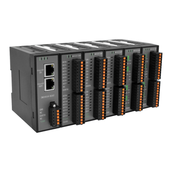
ZMIO310 Vertical Bus Expansion Module User Manual V1.0 Chapter II Product Information 2.1. Nameplate Information Here shows ZMIO310-ECAT, others are the same rule. → Model description:... -
Page 10: Order Information
2.3. Power Requirement This expansion module uses dual-power supply, that is, one coupler module ZMIO310- ECAT or ZMIO310-CAN uses one power supply, then one submodule uses another power supply (when there is enough power for power supply, submodules can use one power supply, but submodule and coupler module can’t use the same one power). -
Page 11: Work Environment
ZMIO310 Vertical Bus Expansion Module User Manual V1.0 ZMIO310-4DA 0.2A 0.1A 2.4. Work Environment Item Parameters Work Temperature -10℃-55℃ Work relative Humidity 10%-95% non-condensing -40℃~80℃ (not frozen) Storage Temperature Storage Humidity Below 90%RH (no frost) Frequency 5-150Hz Displacement 3.5mm(directly install)(<9Hz) -
Page 12: Chapter Iii Coupler Module
ZMIO310 Vertical Bus Expansion Module User Manual V1.0 Chapter III Coupler Module Coupler modules include ZMIO310-ECAT communication module and ZMIO310-CAN communication module. 3.1. ZMIO310-ECAT Communication Module 3.1.1. Interface Definition Mark Interface Number Description Power state: green, it lights when power is The led that conducted. -
Page 13: Performance & Specification
ZMIO310 Vertical Bus Expansion Module User Manual V1.0 User terminal Power terminal 3.1.2. Performance & Specification Item Specification Power Voltage 24V DC Communication Protocol EtherCAT Industrial Real-time Bus Protocol Service CoE (PDO, SDO), firmware upgrade Communication Cycle 250μs, 500μs, 1ms, 2ms, 4ms, etc. -
Page 14: Ethercat Bus Interface Description
Press and fit guide rail buckle of ECAT communication module, then fix ECAT communication module in the DIN guide rail. 3.1.4. EtherCAT Bus Interface Description ZMIO310-ECAT communication module has 2 100M EtherCAT communication interfaces, and it supports EtherCAT protocol. The pin definition is as follows: → Specification... - Page 15 ZMIO310 Vertical Bus Expansion Module User Manual V1.0 Transfer media Cable Transfer distance It is less than 100M between 2 nodes Process data Maximum 1486 bytes of one single frame Synchronization shaking <1us of two slave stations Refresh For 1000 digital inputs and outputs, it is about 30us →...
-
Page 16: Terminal Definition
ZMIO310 Vertical Bus Expansion Module User Manual V1.0 connector and the module in a horizontal direction. Please use tube-type pre-insulated terminals and cables with appropriate wire ⚫ diameters to connect the user terminals. Please don’t mix EtherCAT IN and EtherCAT OUT interface. EtherCAT IN interface is ⚫... -
Page 17: Malfunction Indication And Solution
ZMIO310 Vertical Bus Expansion Module User Manual V1.0 firmly connected. 3.1.6. Malfunction Indication and Solution Status Indication Light Reason Solution twinkle alternately The communication Check if crystal head is loosened or not and slowly between EtherCAT Check the net cable is damaged or not master station and Restart the power. -
Page 18: Zmio310-Can Communication Module
ZMIO310 Vertical Bus Expansion Module User Manual V1.0 3.2. ZMIO310-CAN Communication Module 3.2.1. Interface Definition Mark Interface Number Description Power state: green, it lights when power is The led that conducted. indicates the Run state: green, it lights when runs normally current state. -
Page 19: Installation Size
ZMIO310 Vertical Bus Expansion Module User Manual V1.0 Communication interface CAN Bus interface The number can be connected 16 CAN slave station modules can be connected at most Transfer Distance Less than 40m Address Setting Up to 6 input / 6 output modules are expanded, or 3 AD/DA... -
Page 20: Dip Switch Description
ZMIO310 Vertical Bus Expansion Module User Manual V1.0 3.2.4. DIP Switch Description The ZMIO310-CAN expansion module generally has an 8-bit DIP switch, dial ON to take effect, and the meaning of the DIP is as follows: 1-4: these are CAN ID, used to map IO address of CAN expansion module, the corresponding values are 0-15, different codes relate to different IO starting No. - Page 21 ZMIO310 Vertical Bus Expansion Module User Manual V1.0 → CAN Bus Wiring Method The CAN bus communication parties must ensure that the corresponding GND is ➢ connected, or the main power supply of the communication parties uses the same power supply, otherwise the CAN may be burned.
-
Page 22: Malfunction Indication And Solution
ZMIO310 Vertical Bus Expansion Module User Manual V1.0 3.2.6. Malfunction Indication and Solution Status Indication Light Reason Solution Check whether CAN bus terminal wiring is correct. communicate Check whether 120ohm resistor is connected. abnormally. Check whether the same hardware ID is used by... -
Page 23: Chapter Iv Expansion Sub-Module
ZMIO310 Vertical Bus Expansion Module User Manual V1.0 Chapter IV Expansion Sub-Module 4.1. ZMIO310-16DI: Digital Input Module 4.1.1. Interface Definition Mark Interface Number Description Run state: green, it lights when runs normally The light indicates states. Error state: red, it lights when runs incorrectly... -
Page 24: Installation Size
ZMIO310 Vertical Bus Expansion Module User Manual V1.0 Type of input Digital input PNP (COM1 is connected to 24V power -, COM2 is Voltage input method (power supplied connected to 24V power +) or NPN (COM1 is connected to by IO) -
Page 25: Terminal Definition
ZMIO310 Vertical Bus Expansion Module User Manual V1.0 4.1.4. Terminal Definition → 16 Digital Inputs / IO Power Terminal Number Mark Type Function Input Input 0 Input Input 1 Input Input 2 Input Input3 Input Input 4 Input Input 5... -
Page 26: Wiring Method
ZMIO310 Vertical Bus Expansion Module User Manual V1.0 it with a crimping pliers. →Wire cable connection steps: Press the spring of the terminal to insert the cable with the tubular pre-insulated ➢ terminal into the port. Loosen the spring of the terminal, pull the cable lightly to check whether the cable is ➢... - Page 27 ZMIO310 Vertical Bus Expansion Module User Manual V1.0 → Input Terminal PNP Wiring:...
-
Page 28: Malfunction Indication And Solution
ZMIO310 Vertical Bus Expansion Module User Manual V1.0 4.1.6. Malfunction Indication and Solution Status Indication Light Reason Solution Check whether CAN bus terminal wiring is correct. Check whether 120ohm resistor is CAN communicate connected. abnormally. Check whether the same hardware ID is used by multiple CAN communication modules. -
Page 29: Performance & Specification
ZMIO310 Vertical Bus Expansion Module User Manual V1.0 Mark Interface Number Description The light Run state: green, it lights when runs normally indicates states. Error state: red, it lights when runs incorrectly Connect to coupler modules or expansion Local expansion front level interface submodules, plug in and pull out when in hot are unsupported. -
Page 30: Installation Size
ZMIO310 Vertical Bus Expansion Module User Manual V1.0 4.2.3. Installation Size → Installation Step: ➢ Please use 35mm standard DIN guide rail. Open guide rail buckle of output module, then embed output module in the DIN guide ➢ rail. Press fit guide rail buckle of output module, then fix output module in the DIN guide ➢... - Page 31 ZMIO310 Vertical Bus Expansion Module User Manual V1.0 EARTH Output Output 9 OUT8 Reserved OUT9 Shield OUT10 Output Output 10 OUT11 Output Output 11 OUT12 Output Output 12 OUT13 Output Output 13 OUT14 Output Output 14 OUT15 Output Output 15...
-
Page 32: Wiring Method
ZMIO310 Vertical Bus Expansion Module User Manual V1.0 expansion sub-module. Especially in the case of severe electromagnetic interference on site, different power supplies must be used and they must not share the same ground. 4.2.5. Wiring Method → Output Terminal NPN Wiring:... -
Page 33: Malfunction Indication And Solution
ZMIO310 Vertical Bus Expansion Module User Manual V1.0 4.2.6. Malfunction Indication and Solution Status Indication Light Reason Solution Communication Check whether the local expansion between coupler and behind level interface is loosened. expansion submodule Restart the power. breaks. Check continuation... -
Page 34: Zmio310-4Ad: Analog Input Module
ZMIO310 Vertical Bus Expansion Module User Manual V1.0 4.3. ZMIO310-4AD: Analog Input Module 4.3.1. Interface Definition Mark Interface Number Description Run state: green, it lights when runs normally The light Power state: green, it lights when power is indicates states. -
Page 35: Installation Size
ZMIO310 Vertical Bus Expansion Module User Manual V1.0 Impedance of voltage (input) >1MΩ Range of voltage (input) Dual-pole: -5V~5V, -10V~10V. Single-pole: 0~5V, 0~10V. Range of current (input) 0~20mA, 4~20mA Resolution 16-bit Sample time 1ms/channel Precision (common temperature 25° C) Voltage ± 0.1%, current ± 0.1% (full range) Precision (environmental temperature Voltage ±... -
Page 36: Terminal Definition
ZMIO310 Vertical Bus Expansion Module User Manual V1.0 4.3.4. Terminal Definition → 4-Channel Analog Inputs / IO Power Terminal Number Mark Type Function Current input (+) Channel 0 current input (+) Voltage input (+) Channel 0 voltage input (+) Voltage input (-) -
Page 37: Wiring Method
ZMIO310 Vertical Bus Expansion Module User Manual V1.0 it with a crimping pliers. →Wire cable connection steps: Press the spring of the terminal to insert the cable with the tubular pre-insulated ➢ terminal into the port. Loosen the spring of the terminal, pull the cable lightly to check whether the cable is ➢... - Page 38 ZMIO310 Vertical Bus Expansion Module User Manual V1.0 → Current Input Terminal Wiring:...
-
Page 39: Malfunction Indication And Solution
ZMIO310 Vertical Bus Expansion Module User Manual V1.0 4.3.6. Malfunction Indication and Solution Status Indication Light Reason Solution Communication between Check whether local expansion behind- coupler and expansion level interface is loosened. sub-module breaks. The pre-scanned sub Check if the continuation submodule is... -
Page 40: Zmio310-4Da: Analog Output Module
ZMIO310 Vertical Bus Expansion Module User Manual V1.0 4.4. ZMIO310-4DA: Analog Output Module 4.4.1. Interface Definition Mark Interface Number Description Run state: green, it lights when runs normally The light Power state: green, it lights when power is indicates states. -
Page 41: Installation Size
ZMIO310 Vertical Bus Expansion Module User Manual V1.0 Range of voltage (output) Dual-pole: -5V~5V, -10V~10V. Single-pole: 0~5V, 0~10V. Range of current (output) 0~20mA, 4~20mA Resolution 16-bit Transfer time 1ms/channel Precision (common temperature 25° C) Voltage ± 0.1%, current ± 0.1% (full range) Precision (environmental temperature Voltage ±... - Page 42 ZMIO310 Vertical Bus Expansion Module User Manual V1.0 Current Output (+) Channel 0 current Output (+) Voltage Output (+) Channel 0 voltage Output (+) Voltage/current Output (-) Channel 0 voltage/current Output (-) Shield Current Output (+) Channel 1 current Output (+)
-
Page 43: Wiring Method
ZMIO310 Vertical Bus Expansion Module User Manual V1.0 ➢ Loosen the spring of the terminal, pull the cable lightly to check whether the cable is firmly connected. →Note: When routing terminal cables, avoid bundling them with cables that are with strong ➢... -
Page 44: Malfunction Indication And Solution
ZMIO310 Vertical Bus Expansion Module User Manual V1.0 → Current Output Terminal Wiring: 4.4.6. Malfunction Indication and Solution Status Indication Light Reason Solution Communication between Check whether local expansion behind- coupler and expansion level interface is loosened. sub-module breaks. The pre-scanned sub... -
Page 45: Chapter V Usage Description
ZMIO310 Vertical Bus Expansion Module User Manual V1.0 Chapter V Usage Description 5.1. Power Consumption Calculation Example For coupler module, here, take ZMIO310-ECAT communication module as the example. External ECAT communication module is supplied by DC24V, internal coupler supplies 5V power for each module, the max output current is 2A. Except itself internal power consumption 1.6W, and it supplies 8.4W power for each expansion submodule. -
Page 46: Can Bus Expansion
ZMIO310 Vertical Bus Expansion Module User Manual V1.0 iobase IO start No. Expanded input and output start numbers are the same Example NODE_IO (0,0) = 32 ′expanded IO start No. of Node 0 is 32 IO start number only can be set as multiples of 8, like, 0, 8, 16, etc. If the IO start number is 30, which means it should be set as 24. - Page 47 ZMIO310 Vertical Bus Expansion Module User Manual V1.0 combination value = dial code 4 × 8 + dial code 3 × 4 + dial code 2 × 2 + dial code 1. If the controller itself contains 28 INs and 16 OPs, then the starting address of the first expansion module should exceed the maximum value of 28.
- Page 48 ZMIO310 Vertical Bus Expansion Module User Manual V1.0 DIP 1-4 Starting AD End AD Starting DA End DA combination value number number number number → Communication Speed Configuration Dial code 5-6 to select CAN bus communication speed, speed combination value=dial code 6 × 2 + dial code 5×1, the combined value range is 0-3.
-
Page 49: Read & Write Digital, Analog
Like, the local back-level interface of ECAT communication module (ZMIO310-ECAT) connects to 3 input modules (ZMIO310-16DI), 2 output modules (ZMIO310-16DO / ZMIO310-16DOP), 1 AD module (ZMIO310-4AD) and 1 DA module (ZMIO310-4DA) in turn. ECAT communication module starts to scan and assigns address when it is power- on. -
Page 50: Function Configuration
ZMIO310 Vertical Bus Expansion Module User Manual V1.0 The second submodule ZMIO310-16DI The third submodule ZMIO310-16DI The fourth submodule ZMIO310-16DO The fifth submodule ZMIO310-16DOP The sixth submodule ZMIO310-4AD The seventh submodule ZMIO310-4DA ➢ This expand address is used to build data dictionary, and the address assign is not influenced by expansion submodule type. - Page 51 ZMIO310 Vertical Bus Expansion Module User Manual V1.0 Subindex Sub No. Refer to below Type Data type form tablenum Read the TABLE position that saves data For configurable functions, instruction usage and module function configuration, ➢ please refer to 6.4-expansion example.
-
Page 52: Chapter Vi Data Dictionary Description
6.2. Data Dictionary Overview Below form shows all dictionary overviews of ZMIO310-ECAT communication module. Note: the address of the expansion sub-module is numbered from 0 according to the order of access to the coupler, for example, the first expansion sub-module connected to the coupler has an address of 0, the second expansion sub-module has an address of 1, and so on. -
Page 53: Data Dictionary Details
ZMIO310 Vertical Bus Expansion Module User Manual V1.0 Work mode: normal mode or update mode. Control dictionary. (5001+expansion The number of configured types. submodule address) h Configure or get the type of AD/DA analog range. Configure AD analog channel switch. - Page 54 ZMIO310 Vertical Bus Expansion Module User Manual V1.0 The fixed value is 2. ⚫ CANFIG_1_INDENT 1 or 2 UNSIGND16 ⚫ In indicates the state after power off, resume initial state or keep state. ⚫ The usage of data value: After communication breaks, output states of DO/DOP module and DA module recover initial values.
- Page 55 ZMIO310 Vertical Bus Expansion Module User Manual V1.0 Configure the range type of analog module, or read range type value ⚫ ⚫ The meaning of data values: Module Type Data Value Range Type 0~10V -10V~10V 4~20mA 0~20mA 0~5V -5~5V 0~10V...
- Page 56 ZMIO310 Vertical Bus Expansion Module User Manual V1.0 Configure AD module channel data. ⚫ ⚫ Data value model, namely, correspond to 4 channels of AD module. AD Module Value (16 hexadecimal) ⚫ The meaning of each data value: Data Value Range Type All channels are OFF.
- Page 57 ZMIO310 Vertical Bus Expansion Module User Manual V1.0 Get the input state value of DI module channel. ⚫ ⚫ The usage of data value: 4-digit hexadecimal number is converted into 16-bit binary number, each 1-bit represents the input status of each channel.
- Page 58 ZMIO310 Vertical Bus Expansion Module User Manual V1.0 Configure the output value of DO/DOP module channel, or get the ⚫ output state of DO/DOP module channel. ⚫ The usage of data value: 4-digit hexadecimal number is converted into 16-bit binary number, each 1-bit represents the output status of each channel.
- Page 59 ZMIO310 Vertical Bus Expansion Module User Manual V1.0 Digital converted from AD is represented by Y. Analog gained from DA is represented by X. And AD input value can be calculated from the above graphic: (Y-0)/ (0xFFFF-0) = (X-0) / (5V-0), namely, Y = 0xFFFF*X / 5V.
- Page 60 ZMIO310 Vertical Bus Expansion Module User Manual V1.0 For example: if the current range of AD module is 0~20mA: Digital converted from AD is represented by Y. Analog gained from DA is represented by X. And AD input value can be calculated from the above graphic: (Y-0)/...
- Page 61 ZMIO310 Vertical Bus Expansion Module User Manual V1.0 X value can be calculated reversely. OUT_GENERIC UNSIGND8 ⚫ The number of default subindex, the fixed value is 4. ⚫ Expansion submodule address: the nearest expansion submodule address to coupler is 0, addresses of following other modules accumulate in order, namely, 0, 1, 2, 3…...
- Page 62 ZMIO310 Vertical Bus Expansion Module User Manual V1.0 Analog converted from DA is represented by Y. Digital input from PC, namely, the scale value is represented by X. And DA output value can be calculated from the above graphic: Y-(-...
-
Page 63: Expansion Example
ZMIO310 Vertical Bus Expansion Module User Manual V1.0 calculate value X reversely. 0x0000 OUT_GEN_INT4 UNSIGND16 ~0xFFFF ⚫ Get the output state value of DA channel 3. ⚫ The meaning of date value: 0x0000~0xFFFF means the scale value of analog, input scale values from PC output analogs converted from DA. -
Page 64: Expansion Submodule Address Allocation
ECAT) is sequentially connected to 3 input modules (ZMIO310-16DI), 2 output modules (ZMIO310-16DO or ZMIO310-16DOP), 1 AD module (ZMIO310-4AD) and 1 DA module (ZMIO310-4DA), and the slot No. and device No. are both 0 by default. The address of the expansion sub-module is numbered from 0, and the address of the... -
Page 65: Output State Configuration After Communication Breaks
ZMIO310 Vertical Bus Expansion Module User Manual V1.0 6.4.2. Output State Configuration after Communication Breaks This function is used to keep the output state of DA/DO/DOP after the master-slave station communication is interrupted. There are two modes, and the default is mode 2. -
Page 66: Range-Switch Configuration
ZMIO310 Vertical Bus Expansion Module User Manual V1.0 SDO_WRITE(0,0,$5006,2,6,12) ‘channel 2, 3 are ON. SDO_WRITE(0,0,$5006,2,6,15) ‘full channels are ON. ⚫ This function is valid for current AD module. 6.4.4. Range-Switch Configuration This function is used to switch the range of the input channel... -
Page 67: Get Channel Input State Value Of Ad Module
ZMIO310 Vertical Bus Expansion Module User Manual V1.0 ZM1115 AD module 0~20mA ZM1116 AD module 0~5V ZM1117 AD module -5~5V ZM2111 Output module ZM2112 DA module 0~10V ZM2113 DA module -10~10V ZM2114 DA module 4~20mA ZM2115 DA module 0~20mA ZM2116... -
Page 68: Get Channel Input State Value Of Di Module
ZMIO310 Vertical Bus Expansion Module User Manual V1.0 ? TABLE(100) ‘print read data of channel 0 SDO_READ (0,0,$6051,2,6,100) ‘get input state of channel 1 ? TABLE(100) ‘print read data of channel 1 SDO_READ (0,0,$6051,3,6,100) ‘get input state of channel 2 ? TABLE(100) ‘print read data of channel 2... -
Page 69: Configure Channel Output Value Of Do Module
ZMIO310 Vertical Bus Expansion Module User Manual V1.0 6.4.7. Configure Channel Output Value of DO Module This function is only used to configure the channel output value of DO module, and one of DO module has 16 channels (channel 0-15). - Page 70 ZMIO310 Vertical Bus Expansion Module User Manual V1.0 assignment. '7061h is the DA module control dictionary SDO_WRITE(0,0,$7061,1,6,65535) 'configure output value of channel 0 as 0xFFFF SDO_WRITE(0,0,$7061,2,6,65535) Examples 'configure output value of channel 1 as 0xFFFF SDO_WRITE(0,0,$7061,3,6,65535) 'configure output value of channel 2 as 0xFFFF...
-
Page 71: Chapter Vii Run And Maintain
ZMIO310 Vertical Bus Expansion Module User Manual V1.0 Chapter VII Run and Maintain The correct operation and maintenance of the motion controller can not only guarantee and extend the life cycle of the equipment itself, but also take technical management measures to prevent equipment performance degradation or reduce the probability of equipment failure according to the pre-specified plan or the corresponding technical conditions. -
Page 72: Common Problems
ZMIO310 Vertical Bus Expansion Module User Manual V1.0 Should be within the range of Whether the controller is subjected to vibration resistance vibration or shock impact resistance Keep good ventilation and Is the heat dissipation good heat dissipation The mounting screws should... - Page 73 ZMIO310 Vertical Bus Expansion Module User Manual V1.0 signal for input Check whether the output No. is consistent with channel operated one. Check whether the power of the power supply is sufficient. At this time, it is best to supply power to the...
Need help?
Do you have a question about the ZMIO310 and is the answer not in the manual?
Questions and answers